Duty Cycle
OBJECTIVES :
- To study about the efficiency and losses that occurs in power electronic circuits.
- To show how duty cycle control signal can be generated for a simple power converter circuit in MATLAB.
- To compare square wave inverter output voltage with sine modulated one.
- To explain the difference between VFD and Vector control drive and state the use of VFD method for induction motor in EV application.
CHALLENGES :
1. Why power electronics circuits are efficient? In practice, which types of losses occur in power electronics circuits?
Power electronics involves the study of electronic circuits intended to control the flow of electrical energy. These circuits handle power flow at levels much higher than the individual device ratings. The power electronic circuit contains switches, lossless energy storage elements, and magnetic transformers. A circuit built from ideal switches will be lossless. As a result, switches are the main components of power converters.
Ideally, when a switch is on, it has zero voltage drop and will carry any current imposed on it. When a switch is off, it blocks the flow of current regardless of the voltage across it. Device power, the product of the switch voltage and current, is identically zero at all times. The switch controls energy flow with no loss. In addition, reliability is also high.
If the power electronics circuit is to provide energy of a high power level, as in motor drives or in DC or AC UPS, then the efficiency of the energy conversion is of greatest interest. As all the energy is processed through the electronic circuit, one cannot afford large losses in this process. As a matter of principle, resistors are excluded from such circuits. Special power electronics devices (power insulated-gate bipolar transistors [IGBTs], power Metal Oxide Silicon Field Effect Transistors [MOSFETs], diodes, thyristors, etc. are used as switches to carry large currents and support in high-voltage applications.
Behaviour of current, voltage and power of an ideal switch is as follows,
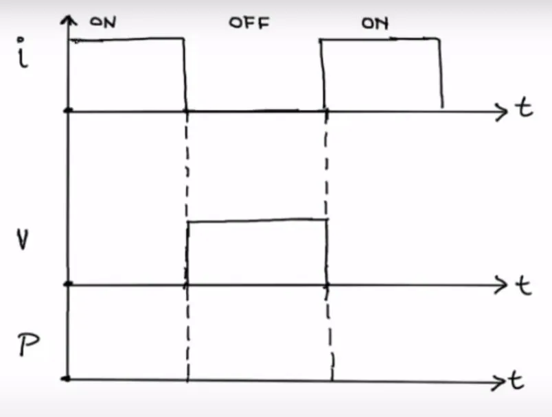
From the above figure, we can say that total power in the switch is zero that means the power losses in an ideal switch is zero.
In practical, there is some amount of power dissipation in the power electronics circuit which is in the form of losses. Mainly there are two types of losses in power electronics, which are switching losses and conduction losses.
Switching Losses – Switching losses occur when the device is transitioning from the blocking state to the conducting state and vice-versa. This interval is characterized by a significant voltage across its terminals and a significant current through it. During this, some energy is dissipated from the device.
Conducting Losses – Conduction losses occur when the device is in full conduction. The current in the device is whatever is required by the circuit and the voltage at its terminals is the voltage drop due to the device itself. These losses are in direct relationship with the duty cycle.
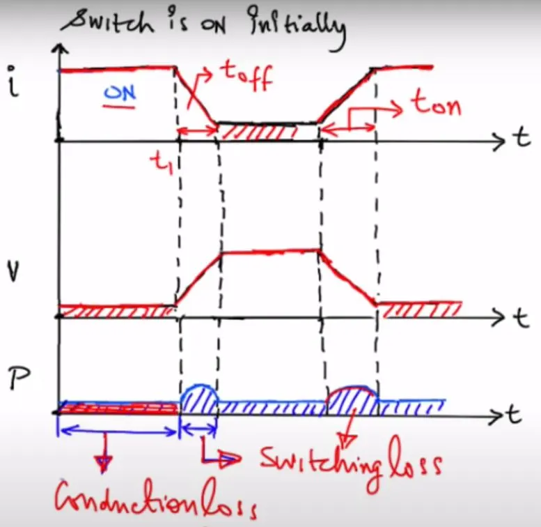
From the above figure we can see that during the ON time of the switch, there is a finite amount of voltage drop across the switch which in turn will cause some power losses in the switch called as conduction loss. When the switch is turned OFF, the current decreases linearly whereas the voltage increases linearly, resulting in some amount of power loss known as switching loss.
2. Using a suitable MATLAB model, show how duty cycle control signal can be generated for a simple power converter circuit?
Here we will use the Buck Converter Model in MATLAB to simulate the nature of the duty cycle control signal. The Buck Converter Model is as follows,
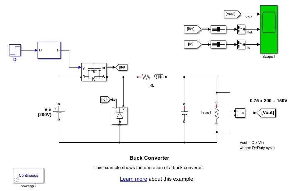
A buck converter is a DC/DC power converter which steps down voltage from its input (source) to its output (load). In continuous conduction mode (current through the inductor never falls to zero), the theoretical transfer function of the buck converter is:
Vout/Vin = D
where ‘D’ is the duty cycle.
In this example, the converter is feeding an RC load from a 200 V source and the PWM frequency is set to 10 kHz.
Simulation –
The parameters for duty cycle is as follows,
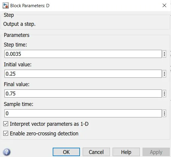
So the initial value is set as 0.25 and final value is set as 0.75. After running the simulation for 0.008 seconds, we get the following result,
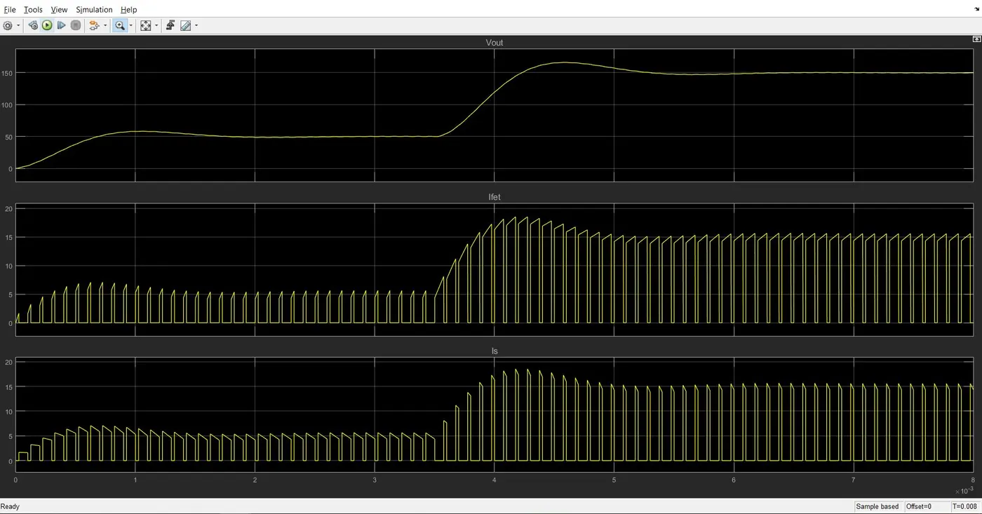
Here we can see that for 0.25 duty cycle, the voltage reaches upto 60 V and for 0.75 duty cycle, it reaches upto 160 V. The Mosfet current Ifet and diode current Is generates duty cycle as per the initial and final values which were mentioned to maintain the output voltage regulation properly. We can see the variation in pulses of the duty cycle which is different in Mosfet and diode to obtain the desired output result.
Now we will change the input parameters as follows,
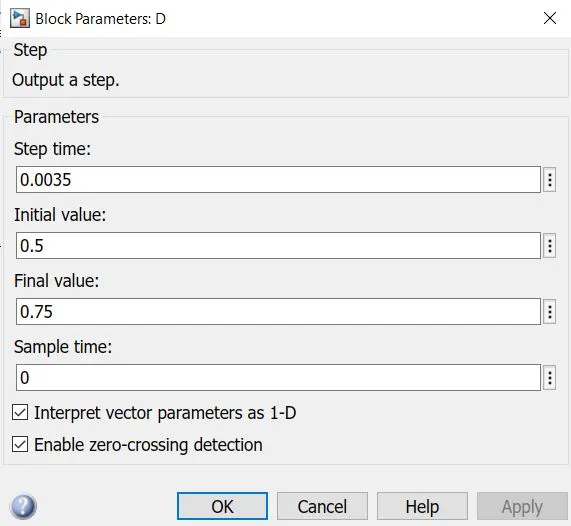
Here we will change only the initial value to 0.5 and the rest of the parameters will be the same. The simulation results obtained are as follows,
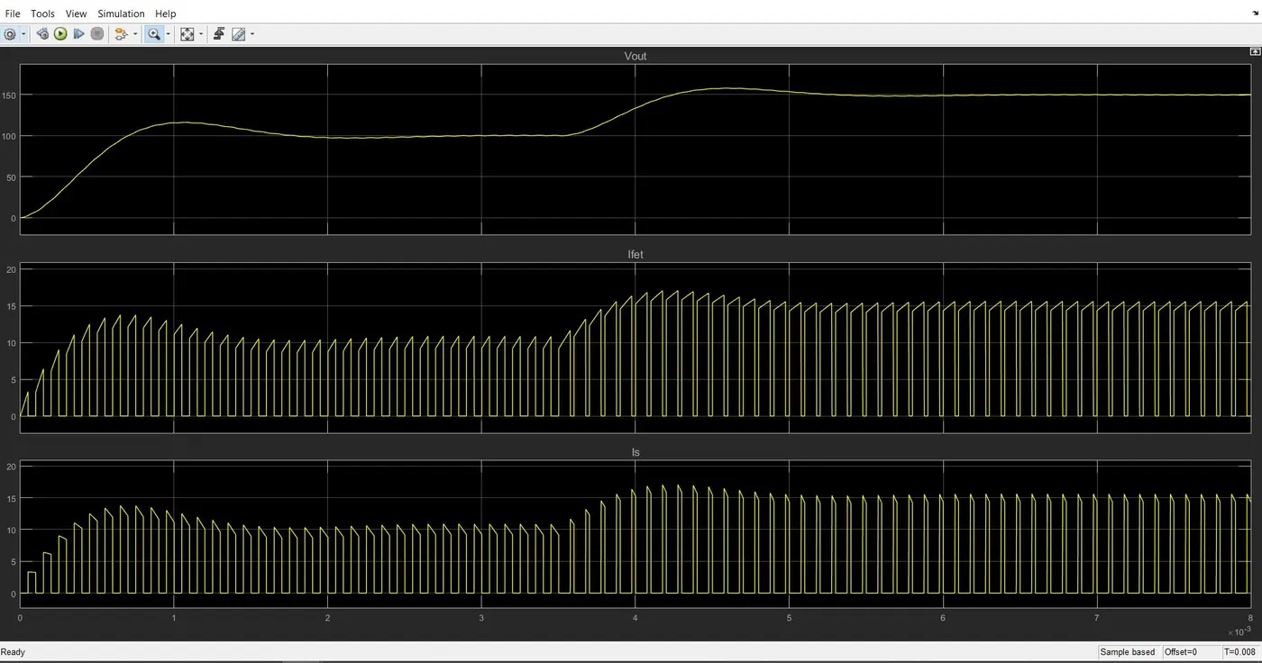
Here we can observer the change in the graph for initial parameter. At 0.5 duty cycle, we get the output voltage as 120 V and also the nature of the graph for 0.5 duty cycle is quite increased compared to 0.25 duty cycle. This states that if the duty cycle pulses increases, the voltage increases with current, increasing the nature of the pulses.
So this is how duty cycle control signal can be generated for a simple power converter circuit.
3. Make a comparison of square wave inverter output voltage with sine modulated one.
The main purpose of an inverter is to convert the DC electricity into AC electricity. An inverter converts DC current to either Square wave AC current or Sine wave AC current. The Sine wave inverter output is very similar to the AC current. In comparison with the Square wave output, the Sine wave output is purer; that’s also the reason why the term Pure Sine wave inverter exists.
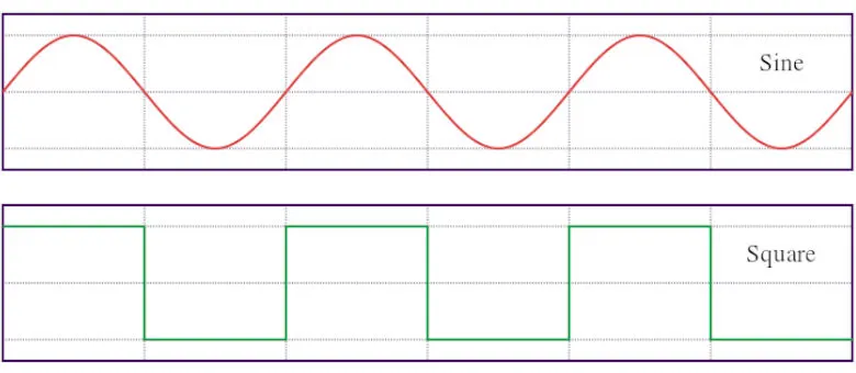
Sine wave inverters are more efficient than square wave inverters, when it comes to the conversion of DC to AC. This ensures that the power loss is minimised, due to greater efficiency.
Benefits of Sine Wave Inverter over Square wave Inverter –
- A sine wave minimises the risk of damage to your sensitive appliances. Compared to a square wave, there is very little harmonic distortion in a sine wave, essential for expensive equipment.
- Devices that use control circuits, which sense the phase for speed/voltage control, or devices that sense instantaneous zero voltage crossing (for timing control) must have a sine wave supply. As we can make out from the figure above, sine wave changes polarity instantaneously and smoothly, when it crosses zero volts.
- The rise and fall of voltage is smooth as compared to the shape of the square wave. Due to this feature, inductive loads (as in motors or microwaves) run quieter, cooler and faster.
- Sine wave inverters are used to support household appliances such as refrigerators ovens, computers, laptops, etc. whereas Square wave inverters are usually used to support motors alone.
- Square wave inverters are less reliable and also unsafe to use for appliances whereas Sine inverters are highly safe to use.
- Square wave inverters produce a very loud noise when used compared to Sine wave inverters which produce normal sound only.
Practically, the square wave can also be modified further using more sophisticated inverters to produce a sine wave. To produce a sine wave output, high-frequency inverters are used. These inverters use the pulse-width modification method by switching currents at high frequency, and for variable periods of time. Using very high frequency helps create very gradual changes in pulse width and thus models a true sine signal. The pulse-width modulation methods have resulted in very efficient inverters.
4. Explain the difference between VFD and Vector control drive. Can we use VFD method for induction motor in EV application?
Variable frequency drive or VFD control method work by optimizing the motor flux and keeping the strength of the magnetic field constant, which ensures constant torque production. Vector control drive controls the speed or torque of an AC motor by controlling the stator current space vectors, in manner similar to DC control methods by transforming a three-phase system that depends on time and speed to a two-coordinate time-invariant system.
VFD control method varies both the voltage and frequency of power to the motor in order to maintain a fixed, constant ratio between the two, so the strength of the magnetic field is constant, regardless of motor speed. Here flux and current cannot be controlled independently whereas in Vector control method, the stator current in an AC motor consisting of the magnetizing component of the current and the torque-producing component, are controlled independently, each with its own PI controller.
VFD control is typically implemented without feedback whereas Vector control drive uses sensors to get feedback for dynamic control. Due to this dynamic response, instantaneous torque control can be achieved in Vector control drive and is absent in VFD control method as it is sufficient in controlling steady state conditions.
Can we use VFD method for induction motor in EV application?
Speed regulation with VFD control is only in the range of 2 to 3 percent of rated motor frequency, so these methods aren’t suitable for applications where precise speed control is required, so the precision control in EV applications cannot be achieved. Also in VFD control, the current and flux are coupled, so current variation affects the flux value. Using VFD method, we can’t decouple the current and flux. This method has low efficiency thus it can reduce the vehicle efficiency. This is why we cannot use VFD method for induction motor in EV application.