Design of Shallow Foundation (Isolated Footings)
AIM:
To design a square footing for a column size of 400x400 for the given data and to do following checks
- If the gross bearing pressure under the footing is within safe bearing capacity
- Provide sufficient depth and longitudinal steel for resisting bending and shear
- Sufficient anchorage for column steel into the footing
- If the bearing pressure at column-footing joint is within 0.45 times the maximum concrete compressive strength
Introduction:
- Footings and other foundation units transfer loads from the structure to the soil or rock supporting the structure.
- The distribution of soil pressure under a footing is a function of the type of soil and the relative rigidity of the soil and the foundation pad.
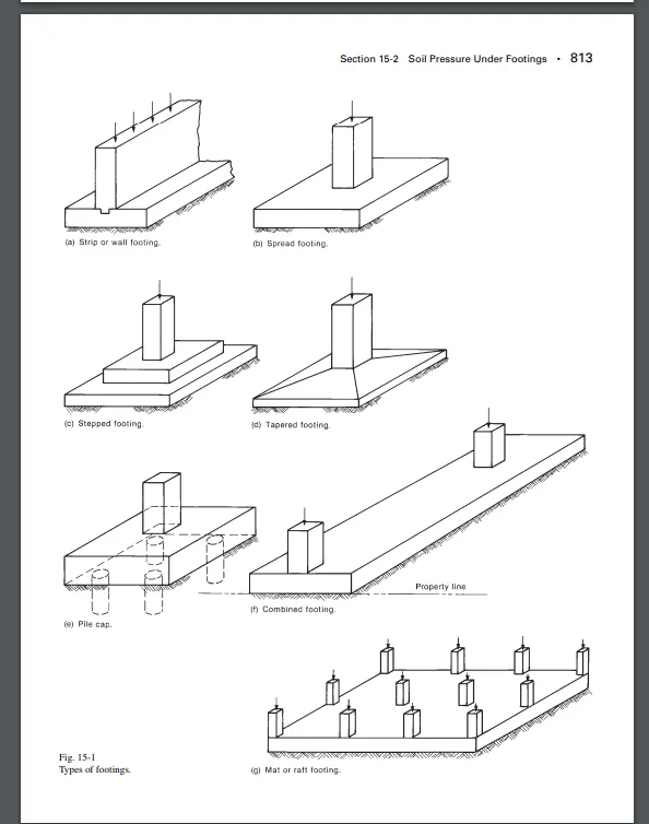
- Most common types of footings used are:
- Strip or wall footing
- Spread footing
- Stepped footing
- Tapered footing
- Pile cap
- Combined footing
- Mat or raft footing
Given data
- Column size = 400x400mm
- Compression axial load (1.5 DL+1.5 LL) = 2000 KN
- Safe bearing capacity of soil = 150 KN/M2 at 2m depth
- Grade of concrete = M25
Calculation of gross soil pressure & footing area:
- Unfactored load with surcharge + self weight of footing / allowable soil pressure
= (2000/1.5 X 1.1) / 150
= 9.78 m2.
Assuming we have square footing √9.78 = 3.12 meter side footing.
Consider, 3.2 meter sided isolated footing.
Net soil pressure & Initial footing depth:
- Factored load / Actual area of footing
= 2000x1000 / (3.2x3.2)
Pn = 195.3 KN/m2
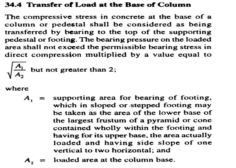
Assume depth of footing 500 mm & checking it for bearing stress as per IS-456-2000 clause 34.4
√(footing base bearing area/loaded area) ≤ 2
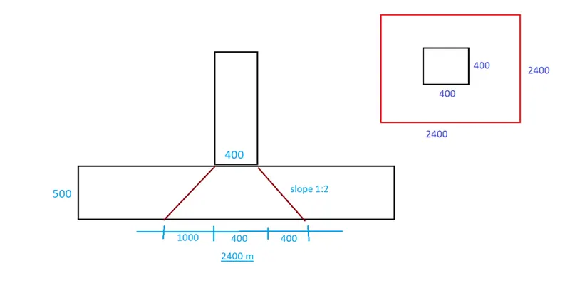
- Permissible bearing stress at Jn = 0.45x Fck = 0.45x25 = 11.25 N/M2
Permissible bearing stress x area factor = 11.25x2 = 22.50 N/M2
Actual bearing stress at base of column
= (2000x1000)/(400x400)
= 12.50 N/M2
Bearing stress at base, 12.50 < 22.50 N/M2
Hence Ok with this depth 500mm.
Taking effective cover as 50mm
Ie effective depth = 450mm
3. Flexural reinforcement calculation :
- Conversion of net pressure into udl
= 195.30 x 3.20 = 625 KN/M
- BM due to udl over cantilever section
= wl2/2 = 625x1.6x1.6/2 (1 = 3.20/2
= 800 KN-m
- Reinforcement calculation as per IS :456 :200 , Annex – G P-96
M = 800 KN-m
Fy = 500 N/mm2
b = 3.20 m
d = 450 mm
fck = 25 N/mm2
Ast = ?
800 = 0.87 x 500 xAstx450 ((1- Astx500/(3200x450x25))
= 195750 Ast – 2.72 Ast
Ast = 4350 mm2
Taking 16mm bar = 4350/201 = 22
16mm bar @ 130mmc/c
Ie 24 x 201 = 4824 mm2, Hence OK
4.One way shear check:
Shear force in the one way shaded area
= 0.95 x 3.20 x 195.30 = 593.70 KN
Design shear stress at one way cut face,
= 593.70x1000 / (3200x450) = 0.412 N/mm2
Shear stress capacity as per IS 456 Table 19
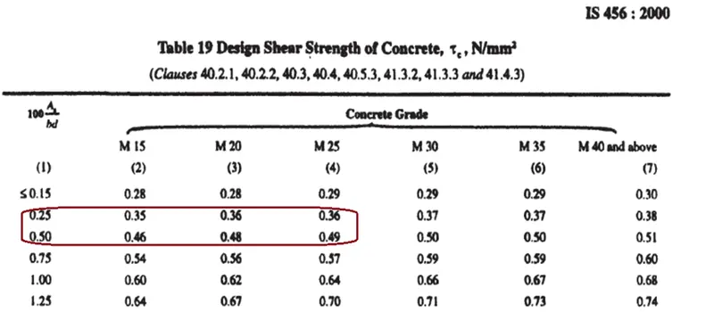
5.Two way shear check:
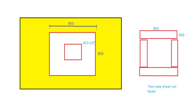
- Shear force in the two way shaded area
= (3.2x3.2) – (0.85x0.85)x 195.30 = 1858.80 KN
Design shear stress at one way cut face,
= 1858.80x1000 / (3400x450) = 1.215 N/mm2
Shear stress capacity as per IS 456 clause 31.6.3.1
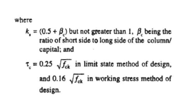
= 0.25 x 5 = 1.25 N/mm2
Design shear (1.215)< Shear stress capacity (1.25),
Hence OK