Design of Shallow Foundation (Isolated Footings)
Q.1) Design a square footing for a column size of 400x400. The compression axial load for the load combination
of (1.5 DL + 1.5 LL) is 2000 KN. The safe soil bearing capacity is 150 KN/m2 at a depth of 2 metres below E.G.L. Participants are free to go for either a tapered or stepped footing. Besides the total axial load, also account for the self-weight of the footing and soil above it. Assume M25 concrete grade. Do the following checks:
- If the gross bearing pressure under the footing is within safe bearing capacity
- Provide sufficient depth and longitudinal steel for resisting bending and shear
- Sufficient anchorage for column steel into the footing
- If the bearing pressure at column-footing joint is within 0.45 times the maximum concrete compressive strength
Provide a simple sketch showing the size of the footing, maximum and minimum depth of the section, flexural reinforcement in both directions and anchorage of column steel.
Ans:-
DESIGN OF SHALLOW FOUNDATION ISOLATED FOOTING
Aim:-
To design a square footing for a column of size 400x400 using some of the informations such as
- The compression axial load for the load combination of (1.5 DL + 1.5 LL) = 2000 KN.
- The safe soil bearing capacity = 150 KN/m2 at a depth of 2 metres below E.G.L.
- Grade of concrete = M25
Then to perform the following checks:
- Calculation of gross soil pressure for footing area.
- Calculation of Net soil pressure for flexure and shear design
- Provide sufficient depth and longitudinal steel for resisting bending and shear
- Sufficient anchorage for column steel into the footing
- If the bearing pressure at column-footing joint is within 0.45 times the maximum concrete compressive strength
- One way shear check.
- Two way shear check.
Introduction:-
- Footings and other foundation units transfer loads from the structure to the soil or rock supporting the structure.
- The distribution of soil pressure under a footing is a function of the type of soil and the relative rigidity of the soil and the foundation pad.
- Most common types of footings used are:
- Strip or wall footing
- Spread footing
- Stepped footing
- Tapered footing
- Pile cap
- Combined footing
- Mat or raft footing.
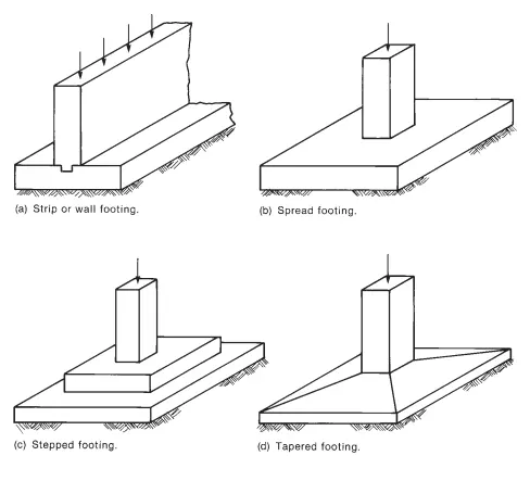
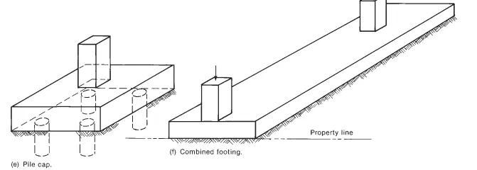
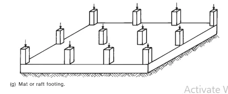
- This project is dealing with isolated footing for a column or spread footing.
Procedure:-
- Given datas include:
- Column size = 400mmx400mm
- Compression axial load (1.5DL+1.5LL) = 2000kN - factored load
- Safe bearing capacity of soil at a depth of 2m below EGL = 150kN/m2
- Assuming the self weight of footing and soil above it as 10% load.
- Assume soil density = 20 KN/m^3
- Grade of concrete = 25kN/m2
- Assuming fy = 500N/mm2
- Here a sloped footing is designed and the steps involved in the design are as follows:
1) Size of footing:-
Calculation of Gross soil pressure:
Unfactored load = 2000/1.5 = 1333 kN
Assume thickness of footing (t) = 0.5 m
Depth of footing as given in data (h) = 2 m, So soil surcharge depth = 2 - 0.5 = 1.5 m
Assume soil density = 18 kN/cu.m
Assume RCC density = 25 kN/cu.m
Consider square shape footing, area of the Footing = b x b = b2
Unfactored or service load = 20001.5=1333.33kN20001.5=1333.33kn/m2
Safe bearing capacity of soil/gross soil pressure , qc = 150kN/m2
Footing area = (Unfactored load with surcharge X self weight of footing)/allowable soil pressure
Hence, the required base area = 1333.33⋅1.1150=9.78m21333.33⋅1.1150=9.78m2
Hence, provide 3200mmx3200mm which gives 10.24m2 base area for footing.
2) Net Soil Pressure & Initial footing depth:-
Net soil pressure= Factored Load/Actual area of footing
= 2000/(3.2 X 3.2)= 195.312 KN/m2 or 0.195 N/mm2
Assuming the depth of footing 500mm and checking it for bearing stress as per IS:456-2000 Clause 34.4
Permissible bearing stress = 0.45 X fck = 0.45X25= 11.25 N/mm2
Permissible bearing stress multiplied with area factor= 11.25X2 = 22.5 N/mm2
Actual bearing stress at column base= (2000X1000)/(400X400)= 12.5 N/mm2
12.5 N/mm2 actual stress is less than permissable 22.5 N/mm2. Hence Okay.
We can proceed with 500mm depth footing for further design checks.
If we assume 50mm cover for footing, the effective depth D shall be taken as 450mm.
3) Flexural reinforcement:-
Conversion of net pressure into uniformly distributed load = 195.312 X 3.2 = 624.99~ 625 KN/m
Bending moment due to UDL over a cantilever section = wL^2/2 = (625X1.6X1.6)/2 = 800 KNm
Reinforcement calculation as per IS:456-2000 Annex G
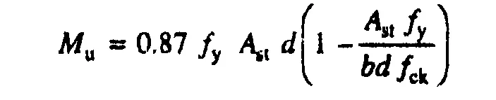
Back calculation in excel file-
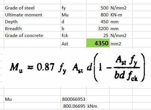
Assume fy= 500 N/mm2, After solving this equation value of Ast= 4350 mm2
If we provide 16mm dia rebar at 125mm spacing, the actual rebar provided = (3200/125) X 201 = 5146 mm2.
4) One way shear stress check:-
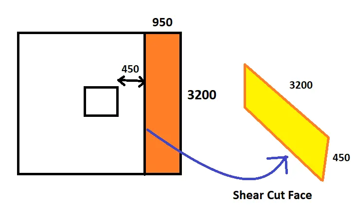
Shear force in the one way shaded area = 0.95 X 3.2 X 195.3 = 593.7 KN
Design shear stress at one way cut face = (593.7 X 1000)/(3200 X 450)= 0.412 N/mm2
Shear force capacity of section as per IS-456-2000 Table-19 (Include rebar) = 0.444 N/mm2
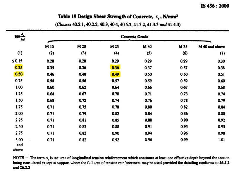
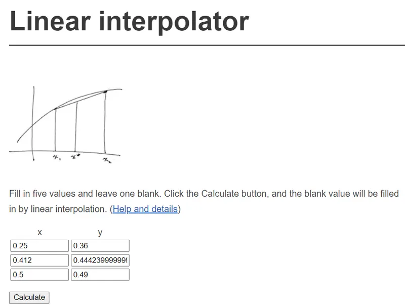
Design shear stress is less than shear capacity.
5) One way shear stress check:-
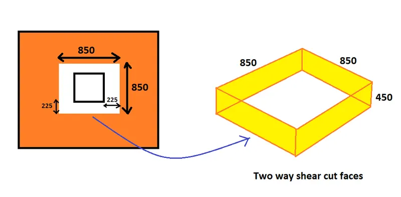
Shear force in the two way shaded area= [(3.2X3.2)-(0.85X0.85)] X 195.3 = 1858.77 ~ 1859 KN
design shear stress at two way cut face = (1859X1000)/(3400X450) = 1.215 N/m
Shear stress capacity of section as per IS-456:2000 Clause 31.6.3.1 

Design shear stress is less than shear capacity.
6) Gross bearing capacity:-
Assuming unit weight of concrete and soil as 25kN/m3 and 18kN/m3
Load on footing = 1333.3kN
Weight of footing = 3.2x3.2x0.7x25=179.2kN
Weight of soil = 3.2x3.2x(2-0.7)x18=239.61kN
Total load = 1333.3+179.2+239.61 = 1751.81kN
Hence, gross bearing capacity = 1751.813.2⋅3.2=171.071751.813.2⋅3.2=171.07kN/m2 > 150kN/m2. we need to increase the size of footing to 3600mmx3600mm.
So, now the weight of footing = 3.6x3.6x0.7x25 = 226.8kN
Weight of soil = 3.6x3.6x(2-0.7)x18=239.61 kN = 303.26kN
Total load = 1333.3+226.8+303.26 = 1863.06kN
Now, gross bearing capacity = 1863.063.6⋅3.6=143.751863.063.6⋅3.6=143.75kN/m2<150kN/m2
So, the corrected net soil pressure = 20003.6⋅3.6=154.3220003.6⋅3.6=154.32kN/m2
Re-Design of Footing
- Bending moment:-
We need to determine the area of steel in one direction as it is a square footing.
If we assume 50mm cover for footing, the effective depth D shall be taken as 450mm
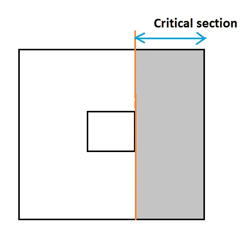
Net soil pressure= Factored Load/Actual area of footing
= 2000/(3.6 X 3.6)= 154.321 KN/m2 or 0.154 N/mm2
Conversion of net pressure into uniformly distributed load = 154.321 X 3.6 = 555.555~ 556 KN/m
Bending moment due to UDL over a cantilever section = wL2/2 = (556X1.8X1.8)/2 = 900 KNm
Reinforcement calculation as per IS:456-2000 Annex G
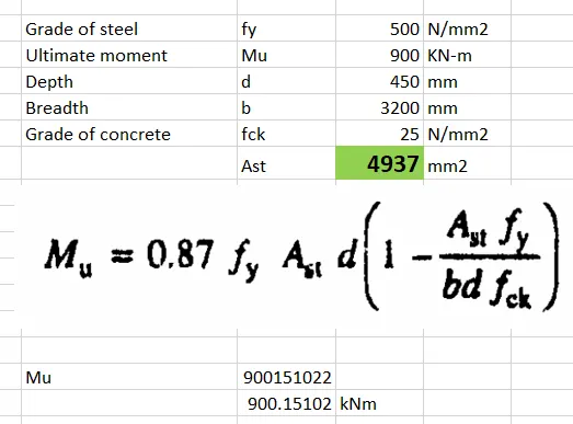
Assume fy= 500 N/mm2, After solving this equation value of Ast= 4937 mm2
So, no. of bars required is given by, 4937314=15.72~164937314=15.72~16bars
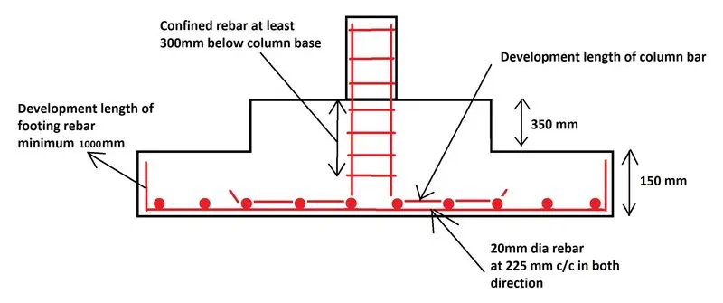
Hence, provide 16 nos of 20mm dia bars both ways.
If we provide 20mm dia rebar at 225mm spacing, the actual rebar provided = (3200/225) X 314 = 5024 mm2.
- One way shear stress check:-
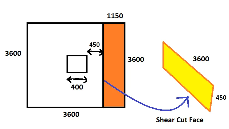
Shear force in the one way shaded area = 1.15 X 3.6 X 154.321 = 638.888 KN ~ 639 KN
Design shear stress at one way cut face = (639 X 1000)/(3600 X 450)= 0.394 N/mm2
force capacity of section as per IS-456-2000 Table-19 (Include rebar) = 0.434 N/mm^2
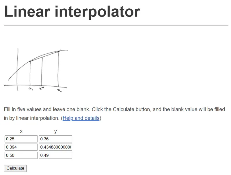
Design shear stress is less than shear capacity.
- One way shear stress check:-
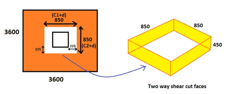
Shear force in the two way shaded area= [(3.6X3.6)-(0.85X0.85)] X 154.321 = 1888.503 ~ 1889 KN
Design shear stress at two way cut face = (1889X1000)/(3400X450) = 1.234 N/mm2
Shear stress capacity of section as per IS-456:2000 Clause 31.6.3.1
Design shear stress is less than shear capacity.
Result:-
Sloped isolated footing for a square column has been designed with the given specification.
Calculation of Stepped footing:-
Critical distance of Oneway shear from column face = 450mm
Critical distance of Twoway shear from column face = 225mm
We have to provide 500mm footing thickness at least 450mm from column face, rounding it off to 500mm uniform around the column.
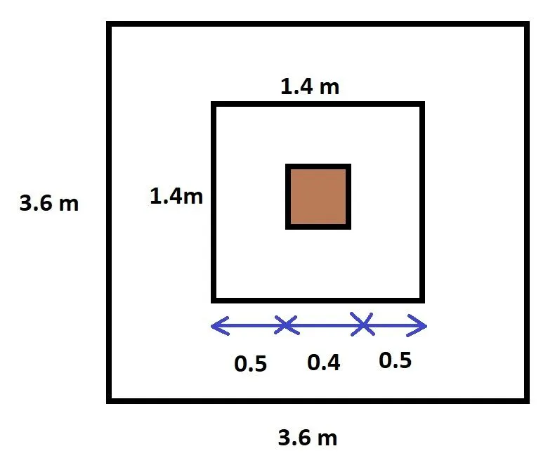
Schematic Representation of Footing step and reinforcement:
Conclusion:-
Thus the required spread footing is designed and detailed as per given inputs. All the reuired limite state criteria are verified and found to OK.