Design of backdoor
VEHICLE BACKDOOR
Introduction:
The Car Backdoor is situated at the rear end of the vehicle. Based on the initial development of vehicle design, the backdoor is supported by hinges present either near to vehicle roof-top, which enables the backdoor to open vertically upwards or the hinges are situated at the left/right sides of the vehicle rear end, to open it on sideways (Right / Left) as observed in most of the SUV’s.
The backdoor of a vehicle is carefully designed, for meeting the requirement of safety and storage accommodation. The amount of space to be accommodated either for luggage or passenger seating are decided by the design and development team.
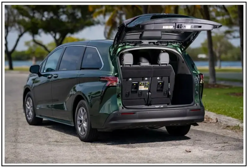
The types of vehicle backdoor opening are shown below,
- Backdoor opening – Vertical upward direction
- Backdoor opening – Side-ways direction (Left/Right)
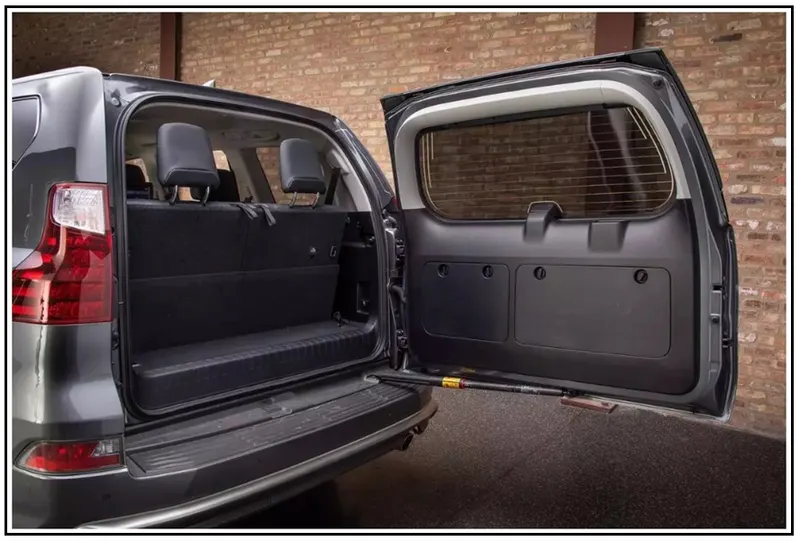
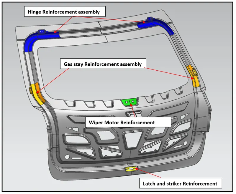
The various components/parts of backdoor are shown below,
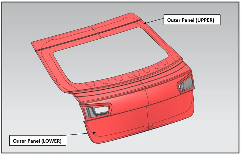
1.) Back Door Outer Panel (UPPER)
2.) Back Door Outer Panel (LOWER)
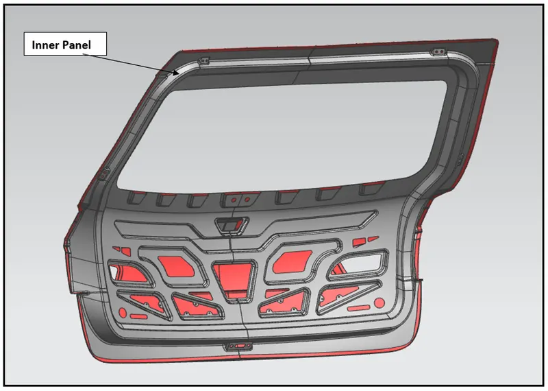
3.) Back Door Inner Panel
4.)Hinge Reinforcement assembly
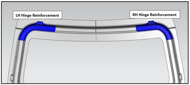
4.1 - Left Hand Side – Hinge Reinforcement
4.2 - Right Hand Side – Hinge Reinforcement
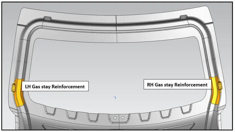
5.) Gas Stay Reinforcement assembly
5.1 - Left Hand Side – Gas Stay Reinforcement
5.2 - Right Hand Side – Gas Stay Reinforcement
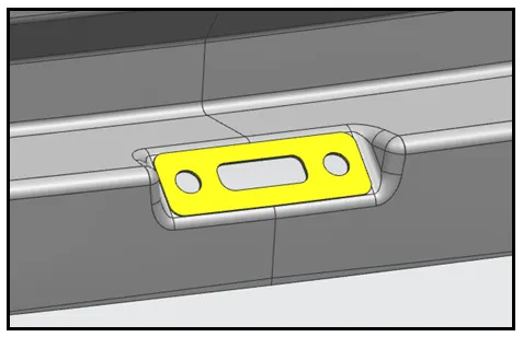
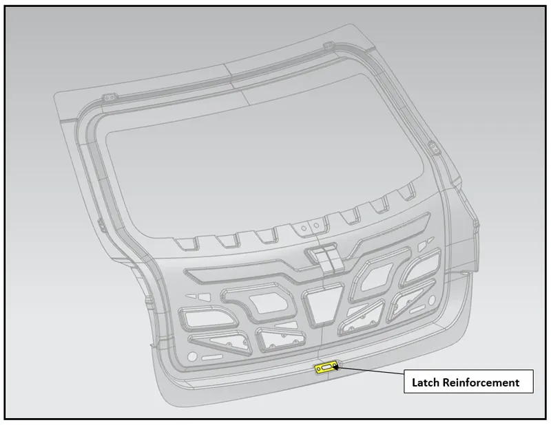
6.) Latch and Striker Reinforcements
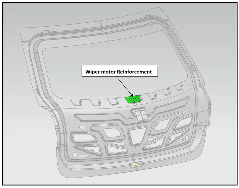
7.) Wiper motor Reinforcements
1.) Back Door Outer Panel (UPPER)
The Backdoor Outer Panel – UPPER PART of the vehicle is the exposed part, which protects the passengers / luggage present inside at the rear end from rain, snow and other foreign objects.
The Backdoor Outer Panel has cut-outs for accommodating the backdoor glass, tail-lamps and mounting hole for wiper motor.
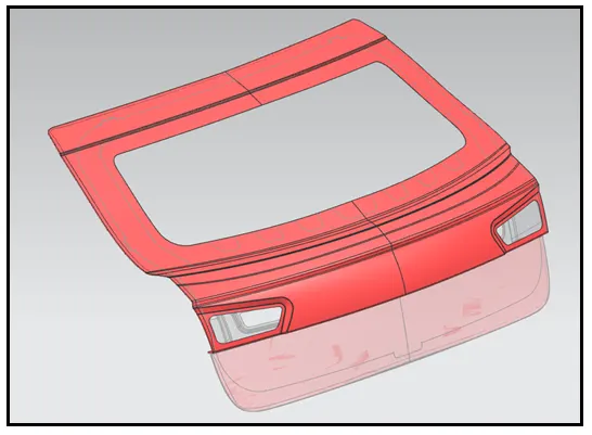
2.) Back Door Outer Panel (LOWER)
The Backdoor Outer Panel– LOWER PART of the vehicle is the exposed part, which protects the passengers / luggage present inside at the rear end from minor collisions/accidents with a less impact.
The Backdoor Outer Panel has space depths for accommodating the name plate and also special attachment facility for mounting the rear-end bumpers.
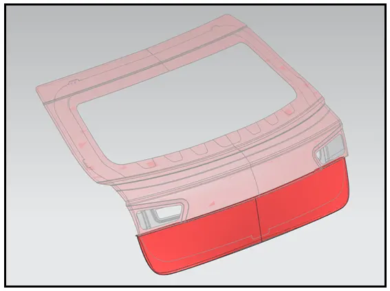
3.) Back Door Inner Panel
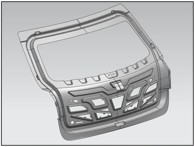
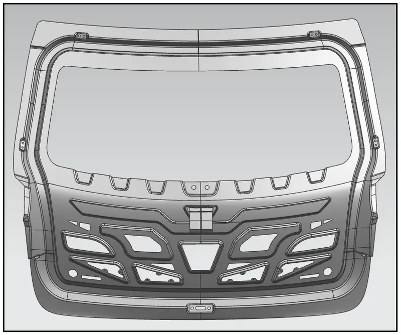
The Back Door Inner panel is the crucial and most important segment of the backdoor. The inner panel forms the skeletal system of the Backdoor.
The Structure of the backdoor inner panel has to be designed with basic requirement of maintaining sturdy strength and absorbing the external impacts by deforming at a minor extent.
The Backdoor Inner Panel has to have certain number of cut-outs at the center part, to make the impact load distributed equally at all directions, thus making the backdoor to maintain uniform stability and good NVH levels.
The reinforcements are to be added at certain region of backdoor inner panel, mainly at the vicinity of hinge points and gas stay mountings, for strengthening purpose to avoid from deformation by the loads acting on it.
The necessary depths and holes are created by stamping process for mounting the hinge reinforcements, gas stay reinforcements, wiper motor reinforcements and Latch and Striker Reinforcements.
4.) Hinge Reinforcement assembly
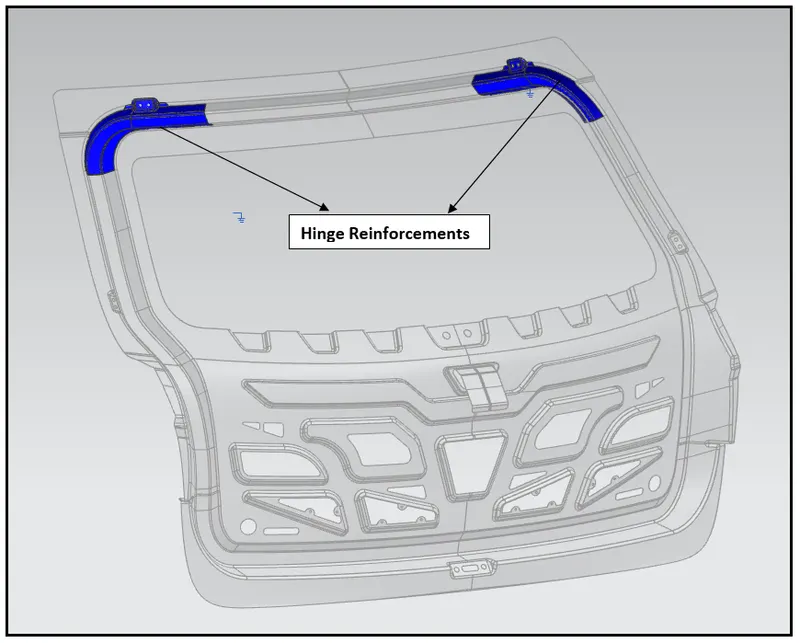
Hinge Reinforcements are added in the Inner Panel of the vehicle backdoor. As the opening of the vehicle backdoor considered for design is of a car with vertical upward movement, the hinges are provided at the rear roof rail.
The Hinges are provided on left and right extreme position of rear roof for a pivotal action of backdoor to facilitate opening and closing operation.
During the opening and closing of backdoor, the self-load of backdoor is being impacted on the hinges, and in turn, may damage the roof structure and hinges at a certain point due to buildup of deformation load.
To avoid the damage of hinges due to stress buildup, the reinforcements are added in the inner panel for hinges to strengthen the local area and increase its life.
The Hinge reinforcement assembly comes with two hinge reinforcements, one for left hand side and other one is on right hand side in extreme backdoor inner panel.
The thickness of Hinge Reinforcement maintained in the design is 0.75 mm.
5.) Gas Stay Reinforcement assembly
Gas Stay systems are the advanced type of supporting system, for lifting the backdoor by the help of a linear actuating device.
Gas stay systems in general reduces the effort on hand for opening the backdoor and also to close the backdoor smoothly.
There are usually two type of gas stay systems – one which is semi-automated type and other is of power driven fully automatic controlled by car key remote or pushbuttons present inside the car.
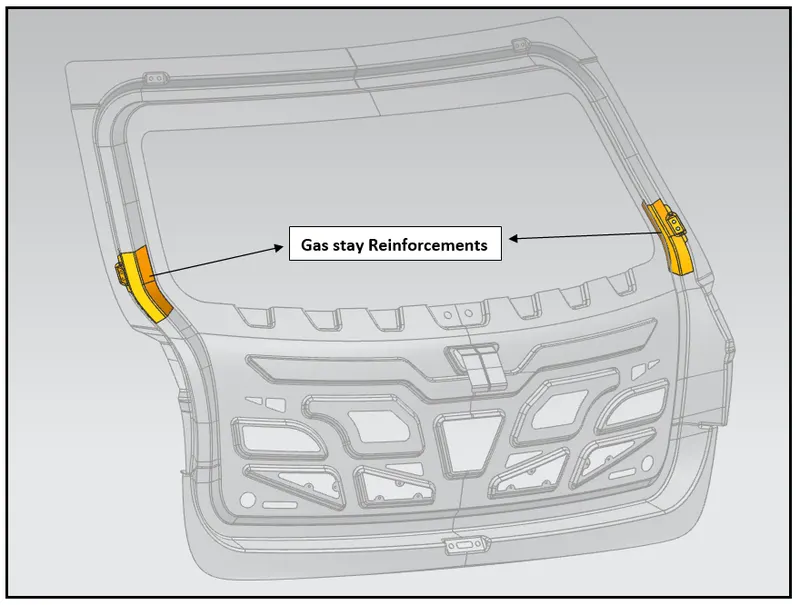
As like hinges, even gas stay system is mounted on the sides of the backdoor. The load of backdoor is supported by gas stay system both during opening and closing operation.
Due to the concentrated load acting on the gas stay systems; its mountings are bound to undergo internal stresses followed by deformation thus damaging the sides of the inner panel. To avoid the deformation, the gas stay reinforcements are added to strengthen the local area of inner panel at the gas stay mountings.
The Gas stay reinforcement assembly comes with two gas stay reinforcements, one for left hand side and other one is on right hand side in extreme positions of sides in backdoor inner panel.
The thickness of gas stay reinforcements maintained in the design is 0.75 mm.
6.) Latch Reinforcements
Latch and striker are the locking system for backdoor. The Latch is present in the rear end at the bottom of the vehicle to engage and disengage the striker present in backdoor while opening and closing operation.
Usually, during opening of the backdoor the pushbuttons near the backdoor outer panel enables to disengage the striker from the latch with less hand effort. But while closing operation, a swift force is provided on backdoor for striker to engage properly to the latch forming a complete locking.
During the closing operation of backdoor, a swift force is provided on outer panel, which impacts the latch area as load is acting perpendicularly by the striker present in inner panel of the backdoor. Due to this quick impact load, the stress is being created on the latch area and which leads to deformation of the local structure.
To enhance the latch structure, the reinforcements are added to strengthen the local area.
The thickness of Latch reinforcements maintained in the design is 0.75 mm..
7.) Wiper motor Reinforcements
Wiper motor is a device which is mounted on the inner panel of the backdoor, just below the glass in center position.
The main function of the wiper motor is to wipe out the water present in the glass of the backdoor. Its commonly used in operation during raining, as the water falls on the backdoor and makes the visibility of the rear road obstructed. Hence, the wiper is switched on, which actuates in to and fro motion on to the surface of the backdoor glass by the help of motor, to wipe of the water and provide clear visibility of rear road.
During the operation of wiper, the motor which makes to actuate the wiper gets heated, which parallelly induces thermal stress at the area of the inner panel near to the wiper motor.
Due to thermal stress induced in the inner panel, the deformation of metal starts to initiate, and henceforth the local area in backdoor inner panel near the wiper motor gets affected. To reduce the deformation, reinforcements are added in the wiper motor mounting to increase the strength of the local area of backdoor inner panel and upper outer panel.
The thickness of wiper motor reinforcements maintained in the design is 0.75 mm.
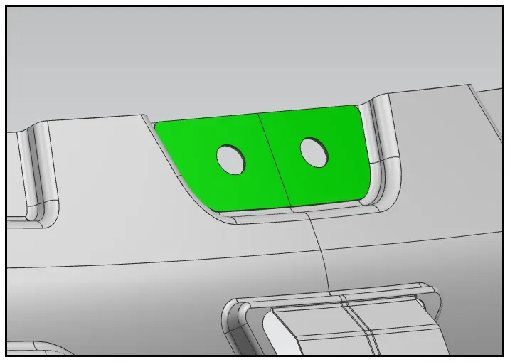
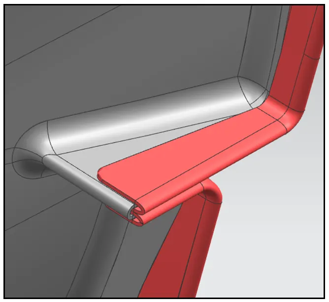
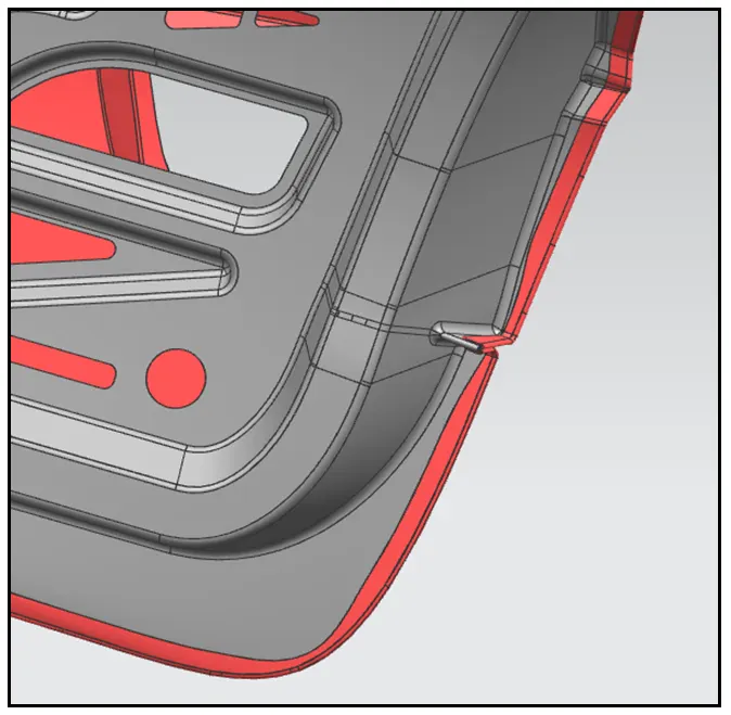
- Hemming Operation
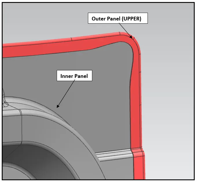
The Hemming operation is performed between the Outer panel (UPPER)/ Outer panel (LOWER) and inner panel of backdoor.
There are two types of Hemming Operation mentioned below,
- Conventional die Hemming.
- Roll Hemming.
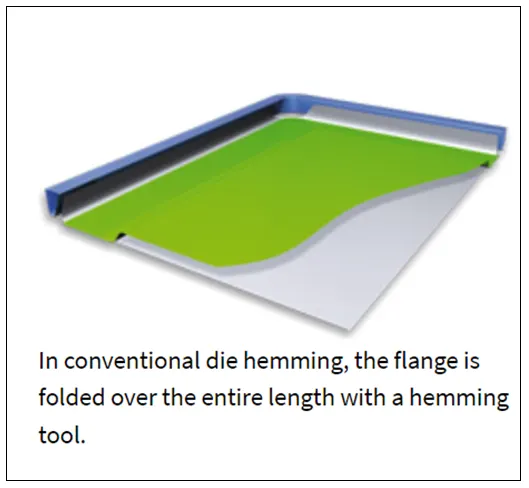
- Conventional die hemming
- Conventional die hemming is suitable for mass production. In die hemming, the flange is folded over the entire length with a hemming tool. Normally the actual hemming is a result of a forming operation in which the flange is formed with a hemming tool after the drawing and trimming operations have been completed.
- The formed flange is then hemmed in several process steps. These steps include, for example, the pre-hemming and final hemming depending on the respective opening angle of the flange.
- Production plants for conventional die hemming are very expensive, but the cycle times are very low.
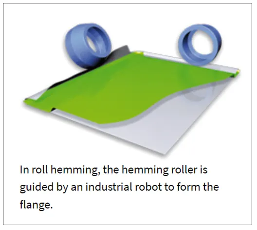
- Roll hemming
- Roll hemming is carried out incrementally with a hemming roller. An industrial robot guides the hemming roller and forms the flange.
- Roll hemming operation can also be divided into several pre-hemming and final hemming process steps.
- Roll hemming is very flexible to use and tool costs are significantly lower as compared to those of conventional die hemming. However, the cycle times are much higher since the hemming is realized using a hemming roller which follows a defined path.
Hemming operation in vehicle backdoor
- DRAFT ANALYSIS ON BACKDOOR INNERPANEL
The sheet metal deep drawn technology is one of the most challenging processes in manufacturing. Drawing operation is the process forming a flat piece of material into a hollow shape by means of punch which causes the blank to flow into the die cavity.
The depth of the draw may be shallow, moderate or deep, various geometries and sizes are made by drawing operation, especially automobile panels.
Typical defects that occur due to incorrect flow of material into the die during the stamping process are wrinkling caused by excessive compression, tearing or splitting caused by excessive tension, and spring back caused by elastic recovery of the material.
During development stage initially one simple design is made. After studying the component data decision is made to make the forming tool for the component.
But, if the side walls of the designed components are having the straight walls having 90 deg. angle with the horizontal plane, then the side walls will rub to the die walls and may lead to adverse effect on die as well as on final product.
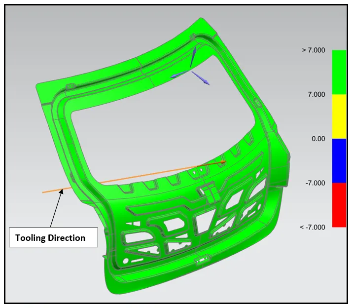
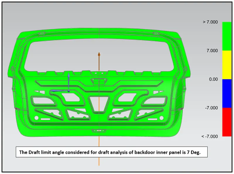
As far as sheet metal forming is concerned it is not possible to press such component without any draft angle for good effect. So, tool designer has requested to product designer to change the design on the basis of analysis results received and incorporate draft angle with a standard limit.
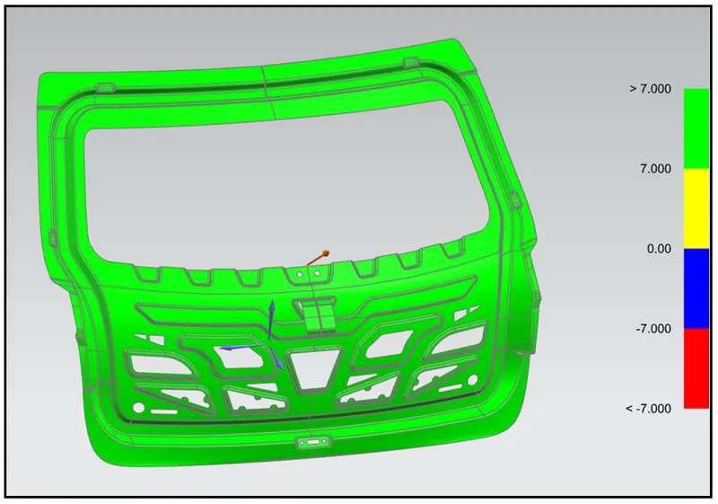
The Draft analysis performed on the Backdoor inner panel is shown in below images,
- BACKDOOR ASSEMBLY
The Backdoor assembly comprising all the subparts are shown in below diagrams: -