Design of backdoor
REPORT
AIM
Using the provided styling surface, create a back door assembly design with inner panel and outer panel.
Provide the necessary reinforcements such as gas stay reinforcements, hinge reinforcement, wiper motor reinforcement and striker reinforcement.
Perform Draft Analysis along the tooling direction.
INTRODUCTION
Backdoor
A Door is a hinged part which is used for entry and exit of the vehicles. Backdoor are one of the type of door of the vehicle which are located next to the passenger seat which provides access to the luggage compartment. In the most of the cars, these back door are operated with the help of gas stay which in turn reduces the effort required to lift the door. Some luxury cars have powered backdoor which in turn is driven by an electric motor. This kind of system is also called a powered trunk lid system hatchback or station wagons are sold as 3 doors or 5 doors models. In this case, the rear hatch is classified as door this is because it enters the passenger compartment. The naming is mainly used in Europe countries. In case of safety, the backdoor designed should meet the safety requirement of the rear collision.
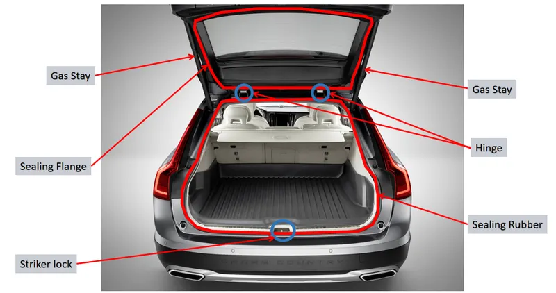
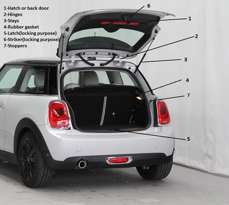
It is a hinged board or door at the rear of the vehicle that can be moved up or down during loading and unloading.
Back Door is also referred as 'Hatch' or 'Tailgate' or 'Trunk-lid' or 'Boot-door'. Its the rearmost part of the vehicle which gives access to the trunk and has mounts for tail lamps, hinges, wiper motor, gas stay etc
Functions of the Backdoor:
- It protects the occupants and luggage from getting damaged.
- It houses assembly of tail lamps, wiper motor and other components.
- It serves as entry and exit point for luggage/passengers.
- It houses windshield glass which helps in rear visibility.
- Parking sensors, rear view camera are mounted on it.
Types of Backdoor
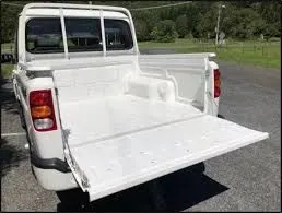
- Top mounted
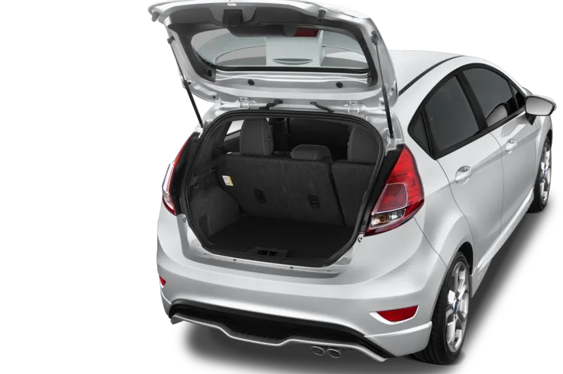
These type of back doors are used in a station wagon, pickup truck and some other sports utility vehicles. Today’s modern cars use top mounted tailgating systems which are both powered and also gas stay supported. These tailgates provide greater rear visibility compared to other types.
- Side mounted
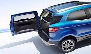
It is generally used in van type MPVs, SUVs, pickup truck vehicles. These side mounted door/barn doors are a lot easier compared to top mounted ones. These doors are generally small in size and can be easily accessed. These doors are more convenient for the goods handlers carrying lengthy objects, long pipes where one door is kept open. It also saves accidental head impacts. It is a lot easier to load /unload things in vehicles having side-mounted doors.
- Bottom mounted
Bottom type or split type backdoor system is used in estate type cars, pickup trucks and some luxury SUVs. These are most convenient type of backdoor in which the bottom split is used as a support or even as a table for the touring people.
Types based on Working Mechanism:
1.Gas Stays type.
2.Powered Lift system.
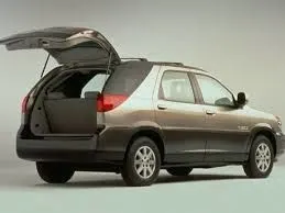
1.Gas Stay type:
Gas Stay type backdoor is an ideal and most commonly used tailgate mechanism from lower segment car to luxury car segment. The ideal components of tailgate consist of a hinge, door, gas stay and some rubber beadings for sealing of door.
2.Powered Lift System:
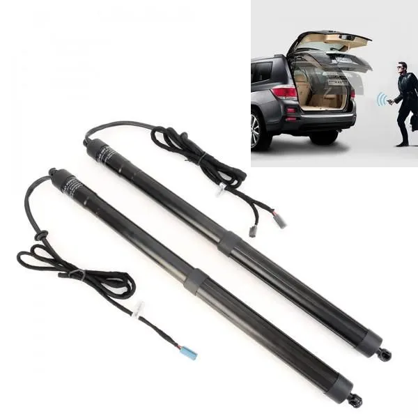
Power trunk lift system is another sophisticated way of trunk or liftgate opening mechanism which is to automatically open and close of the trunk and release of the latch by the touch of a bottom. Powered trunk Lift system consists of a power latch, anti pinch switch, PTG assly, PTG main switch. When the switch is pressed in the compartment or outside the power latch releases the latch and the entire backdoor is opened. The anti pinch switch is located in order to avoid accidental hand insertion during the operation of the door.
DESIGN CONSIDERATION FOR BACKDOOR
1. Rear Visibility.
2. Support structures like hinges and gas stays.
3. Mounts for wiper motor, tail lamps, and other wiring loops.
4. Fit and clearances.
5. Boot space
6.Rear crash regulations and requirements.
7.Sealing and its functions.
8.Joining techniques like hemming, spot welding etc.
MATERIALS USED FOR MANUFACTURING
1. Steel
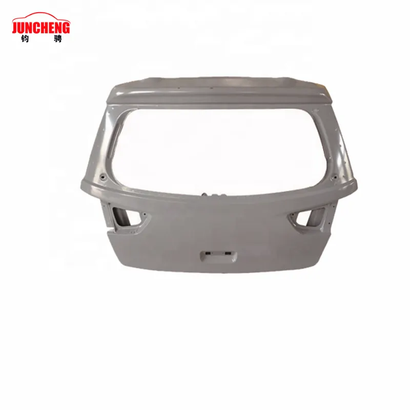
Steel is undoubtedly the most common material used in car manufacturing. Almost every model is designed with some steel simply because it is cheap, strong, readily available, and easy to work. Generally, you can find this steel in parts like brakes, engine, exhaust, wheels, chassis, and roof.
Steel is available in a variety of grades with the lightness increasing proportionately with the expense of making the parts and producing the material. Therefore, car-makers will often utilise more than one kind of steel during the production process – prioritising better steel where they need more reinforcement.
Steel
- Parts are stamped
- Reinforcements are necessary
- Thickness should be uniform
- heavier in weight
- Cheap as compared to Aluminium
- More No. of components
2. Aluminum
Another common metal in the automotive industry is aluminium, which is much stronger and lighter than steel. More importantly, it is completely rust resistant. The downside of aluminium, however, is that it is often much harder to work with and more expensive than steel. Thus, you won’t often see it on cheaper models. Audi and Jaguar are the two manufacturers that are associated with aluminums-constructed cars.The most important reason for substituting steel with aluminium is its light weight and stiffness that enables car makers to improve vehicle performance and fuel efficiency, and meet the safety and emission targets set by legislators across countries.
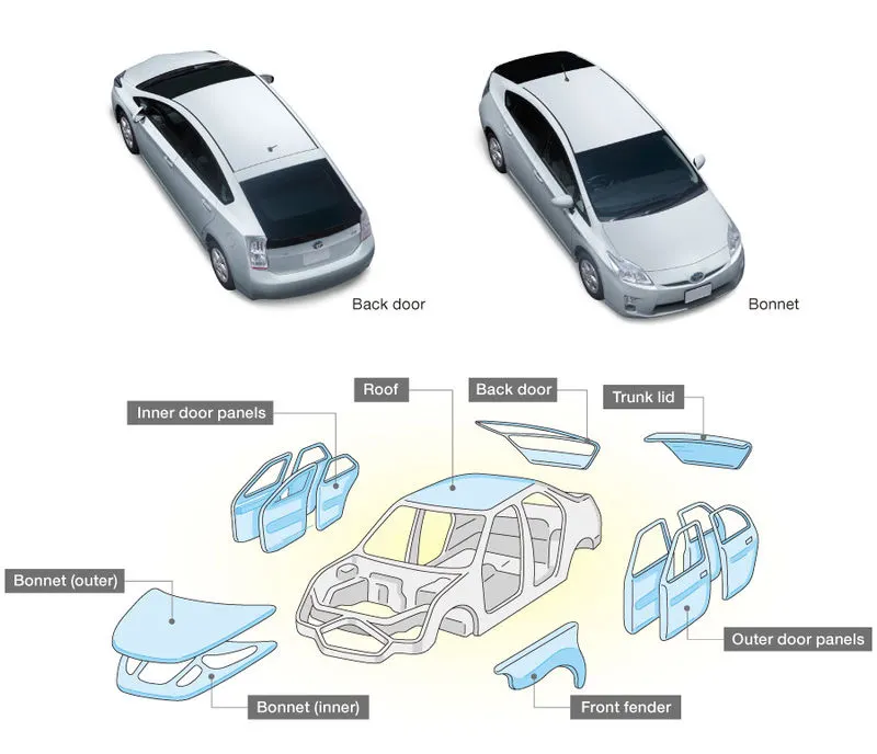
Other advantages of using aluminium include:
- Good impact absorption quality and superior safety
- Production methods are much more energy intensive than those of steel. However, the high recyclability of aluminium makes up the energy consumption during production.
- High corrosion resistance gives it an edge over cast iron in auto parts
The key obstacle for aluminium application is its cost and price stability. Aluminium alloys are three times more expensive than steel; in assembly costs, aluminium is 20-30% costlier.
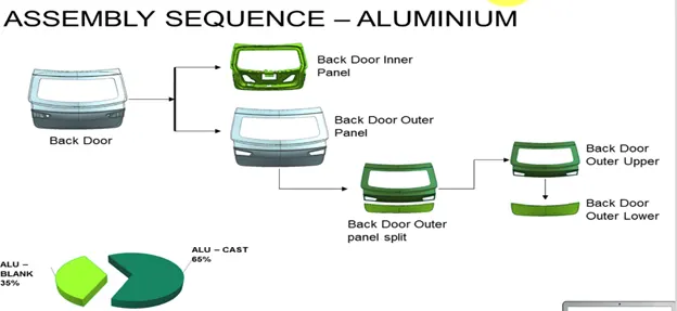
Aluminium
- Parts are casted
- Reinforcements can be neglected
- Thickness can be varied
- Lighter in weight
- Costly as compared to Steel
- Less No. of components
MANUFACTURING PROCESS
STAMPING
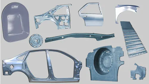
Stamping is a forming process performed on sheet metal by a series of stamping stations. The stamping process used to produce mass quantities of finished products . The stamping of sheet metals can be defined as the process of changing the shape of the sheet metal blank into a useful shape in the plastic deformation state, using a die and a mechanical press; stamping is considered a net shaping process. Generally, the automotive stamping focuses on two modes of stamping: deep drawing and stretch forming. The deep drawing mode is when the sheet metal is formed (drawn) from the binder by the punch. The stretch forming mode is when the clamping pressure of the holding down ring is very high, such that the friction forces in the flange are high enough to allow the material to flow in. The formability of sheet metal can be further analyzed from the metal flow patterns within the die cavity . In stamping, there are three main patterns of metal flow: elastic flow, plastic flow, and rigid movement. Metal stamping is the manufacturing of metallic components by applying an extreme amount of pressure to blank pieces or sheets of metal. The purpose of this metal stamping process is to be able to produce formations of any shape and size desired out of the metal sheet. It has strongly associated with the automobile industry because each car has many parts that are made from steel. Outer car panels, like hoods and fenders, are common examples of parts made using metal stamping processes. Sheet metal stamping presses act as carriages to carry other machines. Dies are fairly simple machines that fit inside and fastened to a press . The steel sheet cuts according to the size of the part and is bent and cut in a stamping machine to make parts such as car doors, roofs, and hoods . In automobile manufacturing process, 60% to 70% of the metal parts are processed by the plastic forming, and a metal forming completes stamping process, such as a variety of car body panels, car parts support, engine exhaust pipe and muffler, hollow camshaft, oil pan, engine cradles, frameworks, structures horizontal beam, etc., are all positive by the precision metal forming technology. Stamping process is the so-called means of stamping parts of the adaptation process that designed in size stampings, precision and base size, structure, and shape with the pressing requirements of processing technology. A car body may contain more than 1500 stampings, in addition to large-scale panel also includes the door, cover, chassis, floor and so on.
DEEP DRAWING
Deep drawing is one of the most widely used processes in sheet metal forming. Apart from its use in many other sectors, it is applied in the automotive industry for the manufacturing of car body parts. The deep drawing process is a forming process which occurs under a combination of tensile and compressive conditions. A flat sheet metal blank is formed into a hollow body open on one side or a hollow body is formed into a hollow body with a smaller cross-section. Deep drawing processes are divided into three types:
Deep drawing with tools
Deep drawing with active means
Deep drawing with active energy
In the automotive industry, deep drawing is usually carried out using rigid tools.
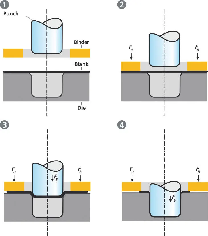
The figure illustrates the deep drawing process. The rigid tools consist of a punch, die and binder. In deep drawing, the plate holder closes after the metal sheet blank has been inserted. Next the sheet is clamped between the die and the binder. This process slows down the flow of the sheet while it is being drawn and thereby prevents wrinkles from forming under the binder. The punch stretches the sheet over the die radius and forms it in the die. The amount of punch force necessary for forming is thereby continually increased up to the lower dead center of the punch. Whereas in pure deep drawing there is no reduction of sheet metal thickness, forming is achieved in stretch forming purely as a result of a decrease in sheet metal thickness. Stretch forming is extensively used for the forming of only slightly curved parts with low depth of draw (e.g. roofs, doors). When drawing complex car body parts in practice, there is usually a combination of stretch and deep drawing involved. It is necessary that the sheet metal is stretched as well as possible without reaching the material's limits (e.g. splits, wrinkles). There are approximately 300 to 400 sheet metal parts which fit together to form the body of a car. In order to manufacture high quality sheet metal parts optimally for their particular use, specialized software simulates the complete deep drawing process.
HEMMING
Hemming is a forming operation in which the edges of the sheet are folded or folded over another part in order to achieve a tight fit. Normally hemming operations are used to connect parts together, to improve the appearance of a part and to reinforce part edges.
In car part production, hemming is used in assembly as a secondary operation after deep drawing, trimming and flanging operations to join two sheet metal parts (outer and inner) together. Typical parts for this type of assembly are hoods, doors, trunk lids and fenders.
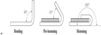
The accuracy of the hemming operation is very important since it affects the appearance of the surface and surface quality. Material deformations, which occur during the hemming process, can lead to dimensional variations and other defects in parts. Typical hemming defects are splits or wrinkles in the flange, material overlaps in the corner areas or material roll-in. This is why it is important to use simulation tools in order to, on the one hand, better understand the hemming process and, on the other hand, significantly reduce the number of “trial and error” loops during tryout und production.
Hems are folds to the edge of a part to create a rounded, safe edge. Hems may be open, flat, or tear-dropped, and tolerances depend on the hem’s radius, material thickness, and features near the hem. The process of creating hems is called hemming.
Hems are created by bending a flange of your part back on itself. This increases the strength of the hemmed edge and also gets rid of any sharp edges, which your technicians (and possibly your future self) will thank you for. The downside (drawback) of hems is that they’re expensive (they usually take three bend operations to form) and add weight to your part.
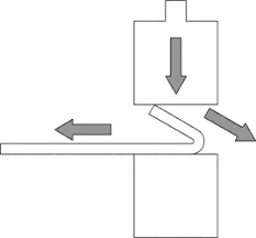
Types of Hems & their design Constraints :
Generally a hem has a round feature and a return flange. Based upon the nature of these two there are various types of hems. We will be looking each one by one below.
1] Open Hem -
As said earlier a Hem has a full round feature and a return flange. In the Open type Hem, bend angle is equal to 180 degrees.
It is recommended that the ratio of the open hem radius to the sheet metal thickness should be greater than or equal 0.5. Also, the ratio of return flange height to the sheet metal thickness should be greater than or equal to 4. For open hems, the minimum inside diameter is equal to the material thickness (larger diameters tend to lose circular shape), and the return length is at least 4 times the material’s thickness.
2] Rolled Hem -
In the case of Rolled Hems there is no return flange available. Here the only design criterias are available for bend radius of hems.
It is recommended that the ratio of the external radius of a rolled hem [R] to material thickness[t] should be greater than or equal to 2.
Also, the ratio of the rolled hem opening [D] to material thickness [t] should be greater than or equal to 1.
3] Tear Drop Hem -
In tear drop hem the bend angle is greater than 180 degrees. It is recommended to consider the following guidelines while designing a tear drop hem -
i) The ratio of the radius of a tear drop hem to the sheet metal thickness should be greater than or equal to 0.5
ii) The ratio of the return flange height to the sheet metal thickness should be greater than or equal to 4.0
iii) The ratio of the hem opening (spacing between the hem edge and the part) to the sheet metal thickness should be greater than or equal to 0.25
3] Closed Hem -
Hems without any inside radius are called Closed Hem. Closed hems are not recommended if the hem geometry is to be painted or if the material used is SST or Aluminum. In closed hems, return flange length from outside the bend should be equal to or greater than four times the material thickness. Generally Closed hems tend to fracture at the bend and cause entrapment of solutions during the finishing process. So one should try to avoid using those in their design until its design requirement.
There are various types of hemming operations:
- Conventional die hemming
- Roll hemming
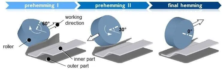
Conventional die hemming
Conventional die hemming is suitable for mass production. In die hemming, the flange is folded over the entire length with a hemming tool. Normally the actual hemming is a result of a forming operation in which the flange is formed with a hemming tool after the drawing and trimming operations have been completed. The formed flange is then hemmed in several process steps. These steps include, for example, the pre-hemming and final hemming depending on the respective opening angle of the flange. Production plants for conventional die hemming are very expensive, but the cycle times are very low.
Roll hemming
Roll hemming is carried out incrementally with a hemming roller. An industrial robot guides the hemming roller and forms the flange. Roll hemming operation can also be divided into several pre-hemming and final hemming process steps. Roll hemming is very flexible to use and tool costs are significantly lower as compared to those of conventional die hemming. However, the cycle times are much higher since the hemming is realised using a hemming roller which follows a defined path.
BRAZING
The industry is faced with ever-increasing requirements concerning productivity, quality, equipment utilisation, and overall customer satisfaction. Sometimes, reducing costs can also improve aesthetics and lead to better automobiles.Because of the high quality of the laser joints, laser brazing is often used in the outer skin area for body-in-white applications within the automotive industry.Case in point: Implementing laser brazing for the ditch joint attaching the tailgates, roof joints and C pillar.
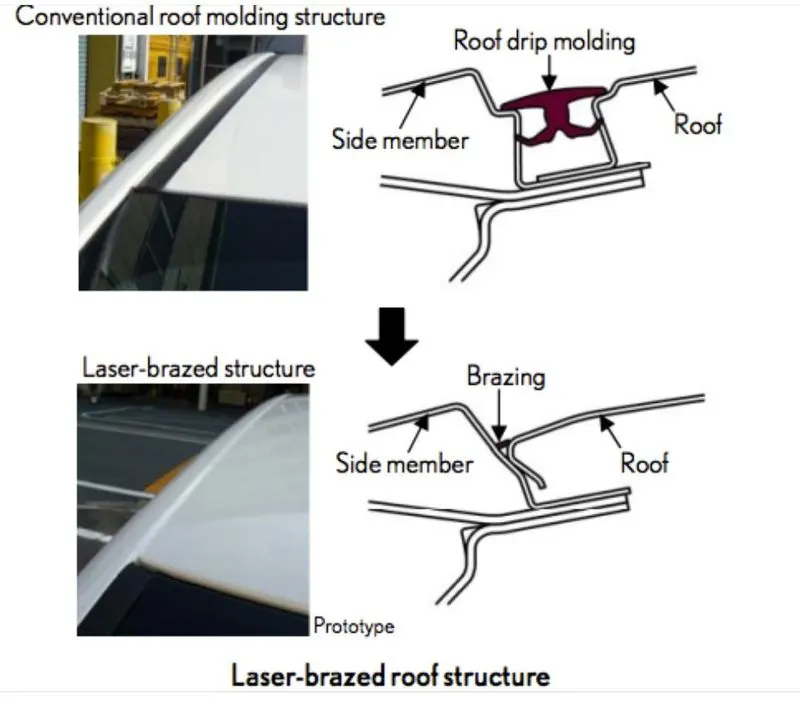
The laser brazing process uses a filler metal for joining without actually melting the base material. This process allows you to achieve high precision and minimal warpage on the workpiece with excellent cost-effectiveness. The materials that you are working with will determine which solder and which process parameters to select.Compared to laser welding or spot welding, laser brazing improved geometrical tolerances and also improves the aesthetics of the joint so dramatically that the ditch molding can be omitted. The consumer gains more benefits: Lighter, quieter, stiffer, and safer cars, and no more extra plastic parts. Doing away with that extra part also means cleaner lines on the car and a lack of dirt-accumulating gaps due to a continuously joined surface.
The first laser joints were hidden or covered welds mainly implemented to reduce flange size and body weight and to obtain stiffer structures . However, laser joining advantages are most apparent in laser brazing of zinc-coated steel or the laser welding of aluminum with filler wire of class A show surfaces. For these surfaces, low warpage, stiff joint ready for the paint shop with almost no post-processing makes it a unique process.
LOAD CASES - GENERAL ANALYSIS
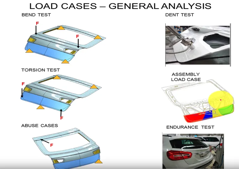
Certain test are carried out in-order to check the strength of back door
- Bend test
The four corners are constrained and force is applied . For every door there will be nominal value at which it will come back to original shape when load is removed.
- Torsion test
The hinge position and latch position is constrained and apply torsion load as shown in figure
- Abuse test
In abuse case its is normally when someone is hanging on the backdoor while in open condition of the back door so the person will apply force on that point where he/she is leaning on.
- Dent test
Dent test in which the load is applied on the panels to see how much force they can withstand.
- Assembly load case
Assembly load case is in which the load which is getting applied while the part gets assembled so that is also we have to test whether the assembled part can withstand itself or not.
- Endurance test
Endurance test is where the back door is opened and closed number of times and after that the results are been observed.
Embosses and reinforcements are provided to improve the strength of the assembly.
BACK DOOR ASSEMBLY
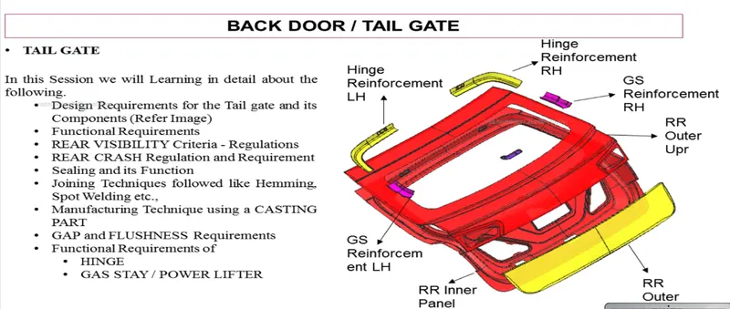
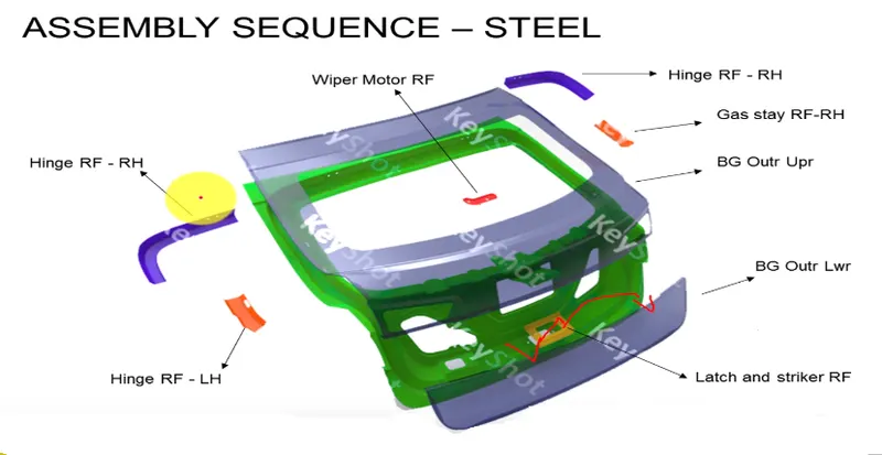
Components
- Back door upper outer panel
- Back door lower outer panel
- Back door inner panel
- Hinge reinforcement
- Gas stay reinforcement
- Wiper motor reinforcement
- Striker reinforcement
Class A surface
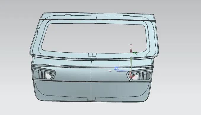
A class ‘A’ surface is provided for the design. If there is any irregularities in the surface provided we have to fix it. Sew operation is carried out to check the surface the gaps and irregularities are cleared and required flanges are created in the class A surface .this is the final surface used as a reference to create all other part in the assembly. The surface is created as two part, back door upper panel and back door lower panel.
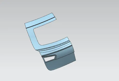
BACK DOOR UPPER OUTER PANEL
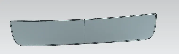
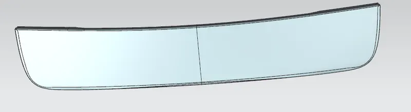
After creating the back door upper outer panel from class A surface hemming is created on the panel for joining with inner panel.the panel is thickened to .75mm.Hemming is a forming operation in which the edges of the sheet are folded or folded over another part in order to achieve a tight fit.hemming is used in assembly as a secondary operation after deep drawing, trimming and flanging operations to join two sheet metal parts (outer and inner) together.hemming is created by offsetting the surface to 2.65mm( by considering the thickness of inner panel(.75mm), outer panel(.75mm), hemming surface(.75mm) and gap between panel for providing sealant(.2* 2).
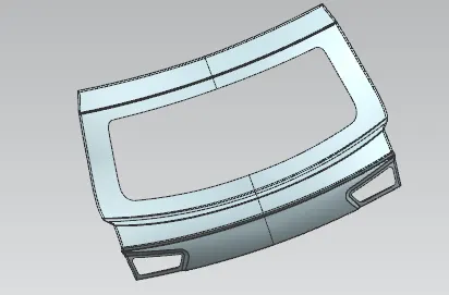
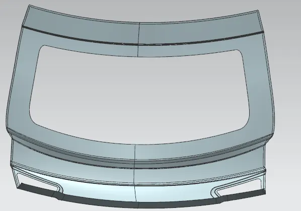
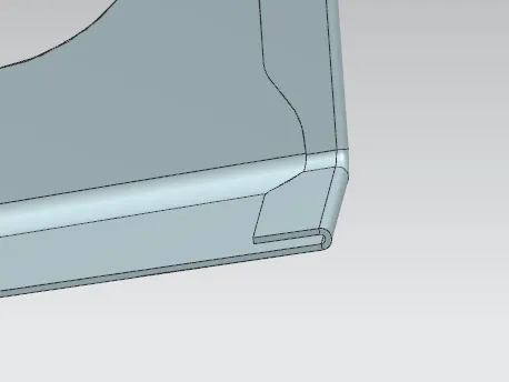
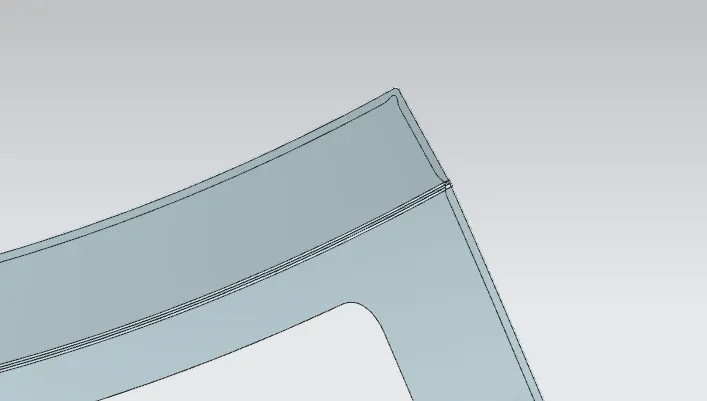
hemming and relief in outer panel
BACK DOOR LOWER OUTER PANEL
Similarly in lower panel also hemming is created and the panel is thickened to .75mm.
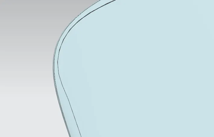
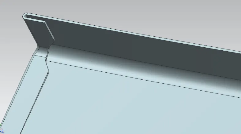
During the hemming process, when giving the Corner Relief helps to control sheet metal material behaviour & to prevent unwanted deformation during unbend operations & also helps to minimise the number of passes in hemming.corner relief is provided for both upper and lower panel for hemming process
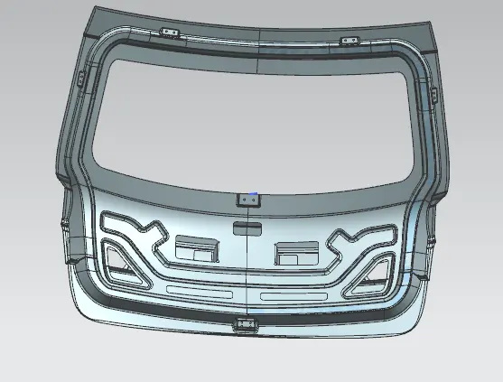
BACK DOOR INNER PANEL
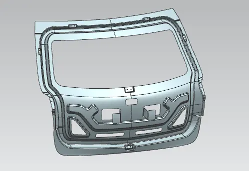
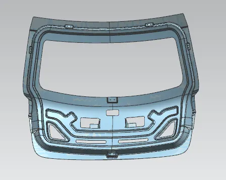
The inner panel is created with reference of the outer panel created from class A surface. The surface is extracted using wave geometry linker and offsetting to a distance of 1.7mm (considering the thickness of inner panel and outer panel and the gap for hemming)
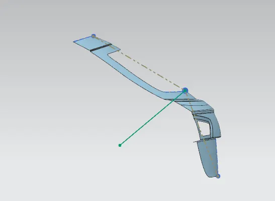
The tooling direction
The part is produced using deep drawing process . For manufacturing the part a tooling direction is required. Two different lines are created from the extreme edges. A bisecting line is created and this is fixed as the tooling direction of the part.
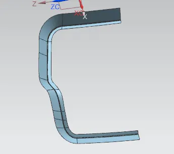
Sealing flange
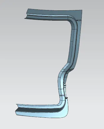
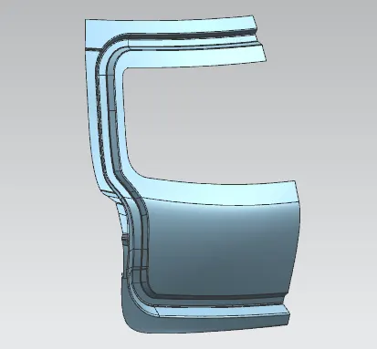
Sealing flange is the surface which allows the back door to sit on the body. Sealing flange is the most important part of the inner panel as it decides how a backdoor is mounted on the rear body side of the car and also restricts any external matter to enter inside the vehicle.
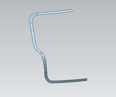
Windshield area and bottom portion
Emboss:
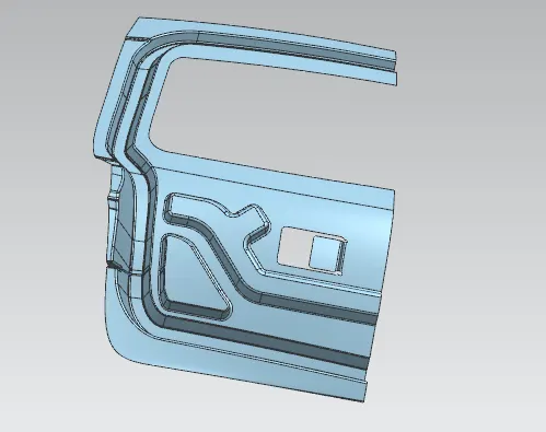
We provide different embosses throughout the inner panel. We can increase the stiffness of the inner panel through these embosses. The shape and size of the embosses also determines the direction of the force distribution resulted from collision . it will also decipate the force from the impact to outwards.
The embosses were created in ‘V-Shape or Y-Shape’ so that if the vehicle undergoes the crash then the force dissipates over it which reduces the damage transferred to the trunk space.
Mastic flange
Back door commonly possess large surface area and hemming can only be provided through its boundary. We cannot use other joining techniques like welding, riveting etc because they leave marks on the outer panel which spoil its aesthetic appearance. So, mastic sealants are used to stick the inner surfaces of outer panel and inner panel. Mastic sealants are elastic compound that behave like rubber. It is applied between the inner and outer panels at specified spots.a flange is created from the inner panel at a distance of maximum 5 mm from the outer panel for applying the mastic seal
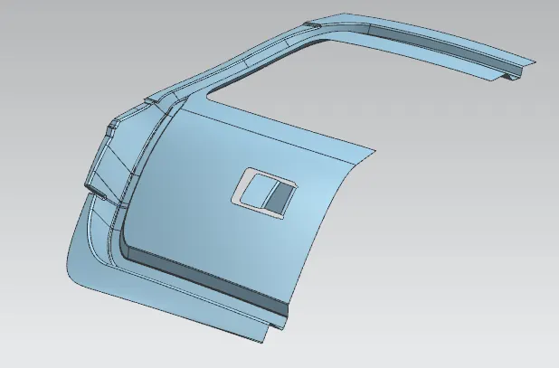
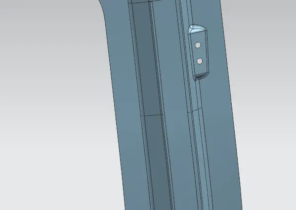
Hinge emboss
Hinge emboss is created for fixing the hinges.it should be designed in such a way that the emboss should have flat surface for assembling the hinges.
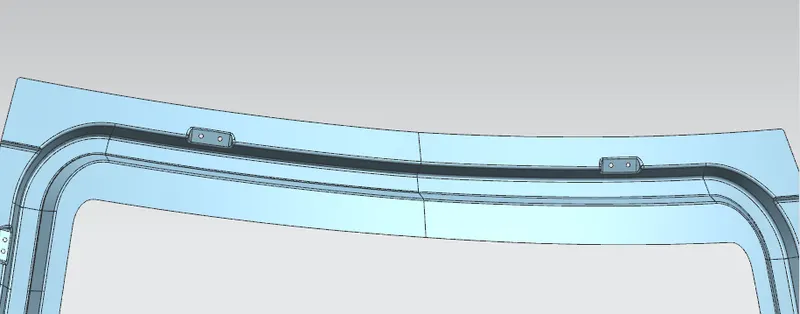
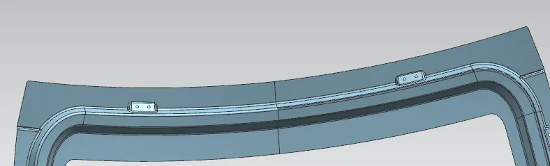
Gas stay emboss
Gas stay emboss is created for mounting the gas stays and the surface of the emboss should be flat and make sure that the it can be manufactured using single tooling direction
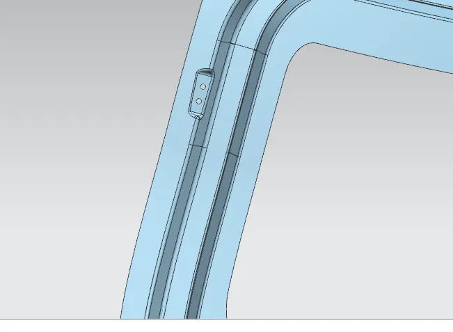
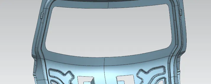
Wiper motor emboss
Wiper motor emboss is created for fixing the back door wiper assembly.
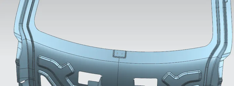
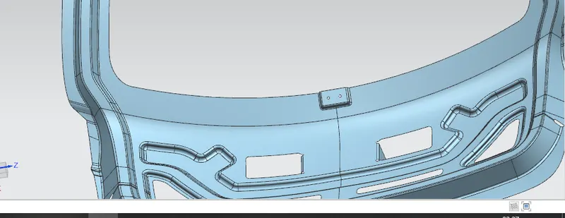
Latch and Striker emboss
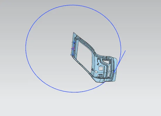
Backdoor is the swinging part which rotates about hinge axis. The position and orientation of latch striker is important for proper opening and closing of the backdoor. The position of the hinge should be perpendicular to the latch at the time of latch and striker meets. The circle is drawn from the centre of the hinge axis to find the path of the striker.a tangent is drawn to the circle to get the perpendicular line. Emboss surface is created with respect to the perpendicular line as shown in figure
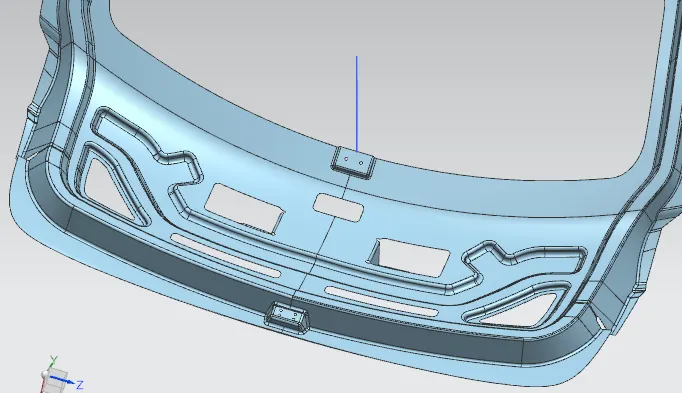
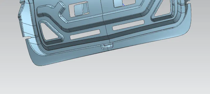
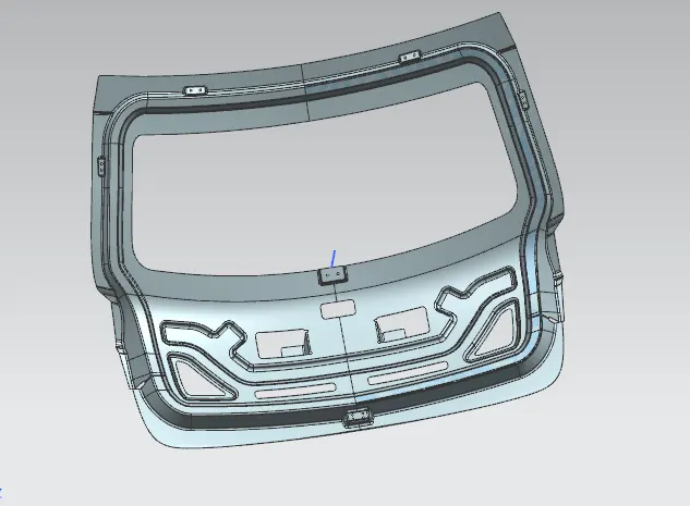
The inner panel is thickened to .75mm
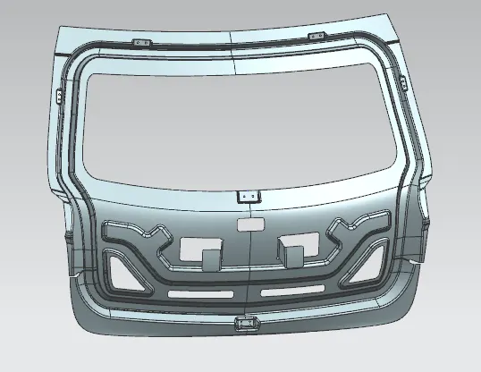
HINGE REINFORCEMENT
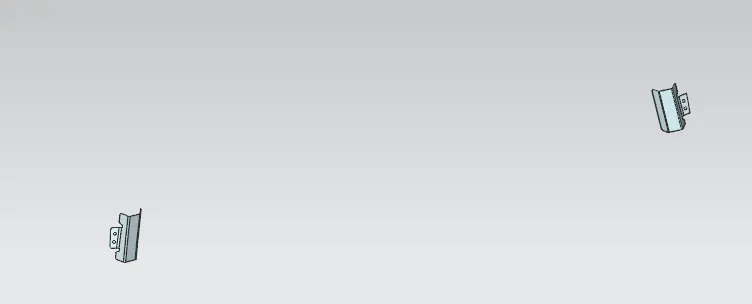
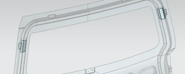
The back door is supported by the hinge for opening and closing.for fixing hinge in the backdoor we need to provide emboss there, because of emboss and hole its strength got affected so to compensate that we provide hinge reinforcement. Hinge reinforcement has thickness around 1 to 1.5 mm to provide reinforcement to hinge embossed region.
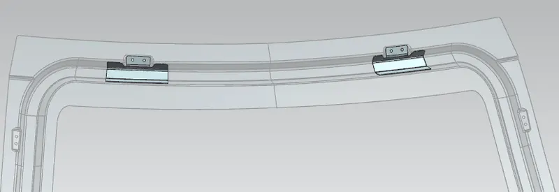
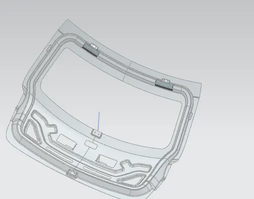
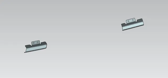
GAS STAY REINFORCEMENT
Gas stay support the back door in opening of back door. For improving the strength in that region gas stay reinforcement with thickness of 1.5 mm is provided in the emboss region
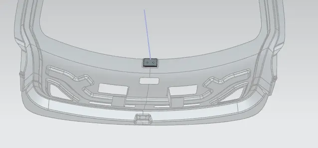
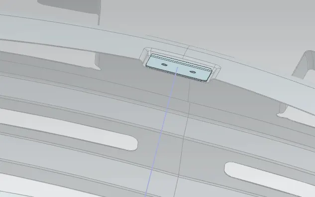
WIPER MOTOR REINFORCEMENT
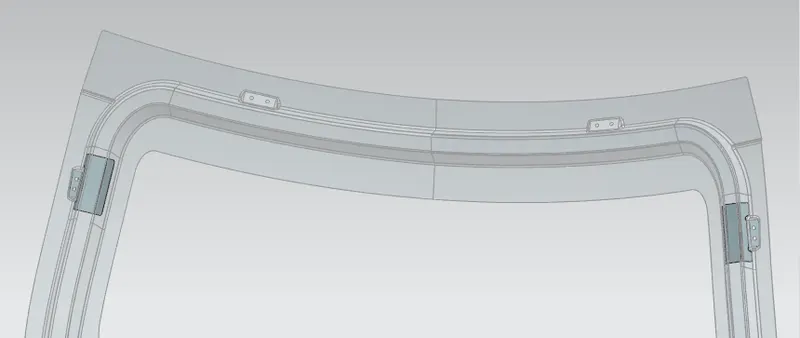
Reinforcement of thickness 1.5mm for wiper motor mounting region.
STRIKER REINFORCEMENT
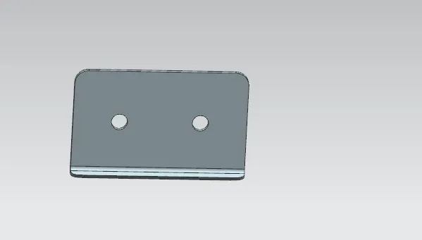
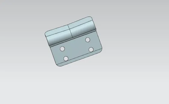
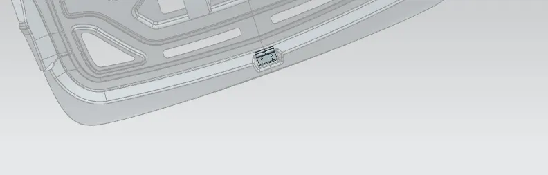
It is the reinforcement of thickness 1.5 mm provided in the striker emboss region.
BACK DOOR ASSEMBLY
DRAFT ANALYSIS
The Draft Analysis command enables you to detect if the part you drafted will be easily removed. This type of analysis is performed based on colour ranges identifying zones on the analysed element where the deviation from the draft direction at any point, corresponds to specified values.Draft Analysis is a method of checking the draft angle on various faces of a part in a particular direction. The draft angle should be positive for the feasibility of manufacturing the part. Generally, we take draft angle 7 or greater than 7. The draft analysis was conducted for the following sections considering tooling direction as the vector
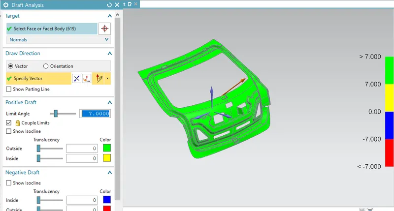
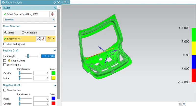
The Draft Analysis command enables you to detect if the part you drafted will be easily manufactured. This type of analysis is performed based on colour ranges identifying zones on the analyzed element where the deviation from the draft direction at any point, corresponds to specified values.
Draft analysis is done for parts in assembly and it fullfill the criteria of tool opening angle of 7 degrees.
CONCLUSION
Using the styling surface back door assembly is created with components with appropriate design methodologies and the necessary reinforcements and embosses.
- Back door upper outer panel
- Back door lower outer panel
- Back door inner panel
- Hinge reinforcement
- Gas stay reinforcement
- Wiper motor reinforcement
- Striker reinforcement
- Draft analysis is done for the parts along the tooling direction it fullfill the criteria.