Design of backdoor
Objective
Designing of car's back door using Nx cad software.
STEPS
We have given with outside surface of back door and the surface A given has some faults.So we correct the surface A.We use the modified surface for further component creation.The back door has components like back door inner pannel,outer upper back door surface, outer lower back door surface and reinforcement parts.
The design consideration of back door are some follows -
- Should provide enough visibility to the back area
- Should have emboses to reduce the impact during collision to the passengers and things inside the cabin
- Should provide sealing from the outside atmosphere
- Inner pannel should be designed to keep enough laguage in the laguage space
�
inner pannel
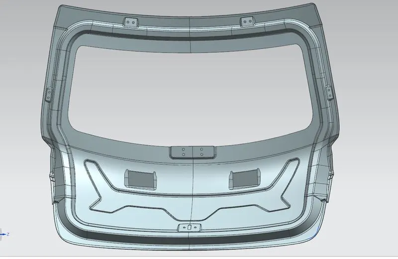
First we create a tooling axis to create inner pannel of back door.The tooling axis is made by taking intersection between two surface line from the outer surface given.The inner pannel is created according to the tooling axis.Ceiling flange is created on the inner pannel to create entring of moist, dust etc from the surroundings to the cabin.Inner pannel also has features to attach the back door wind shield,whiper attachment mound etc.So the design should be according to it.The emboses on the surface of inner pannel are created according to tooling axis.But we can create emboses apart from current tooling axis.
The inner pannel of the back door is created by offsetting from the outer pannel.Since we have given two surface as outer surface (upper and lower surface) ,the inner pannel is created by merging both upper and lower surface from offsets.

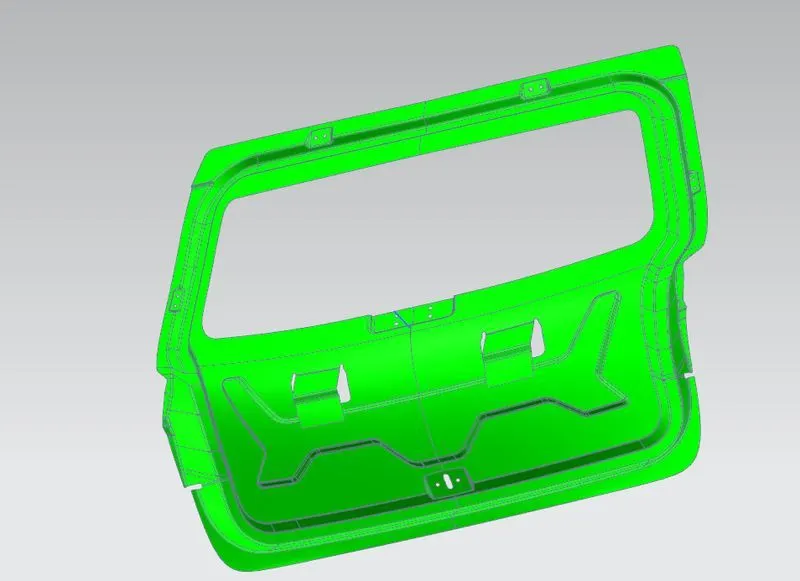
The above image is the final inner pannel we created.and by doing the draft analysis with the tooling axis we got minimum draft of 7 degree on all surfaces of inner pannel
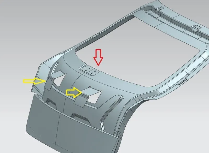
In the inner pannel we also provide a supporting surface to hold inner pannel and outer pannel together. in between the supporting surface and outer pannel; mach sticks are provided to join together.the yellow arrow marked is supporting surface .
The red arrow showed is the whiper attaching emboss..
outersurface
since we have 2 surfaces (upper and lower) ; we create seperate outer pannel for both surface.for each pannel there is seperate tooling axis to create.By doing draft analysis we found these results.
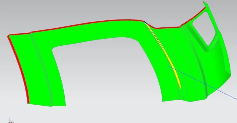
The upper surface's draft analysis is showed above.here the red region is the region where the hemming comes.But the yellow region at the middle of the surface shows draft angle between 7 and 0 degree to tooling axis.Here the tooling axis is created by intersection between two almost parallel surface lines.
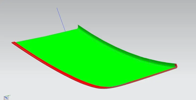
The above result is draft analysis for the lower surface.here too the red region shown is the hemming region.Rest of the all surface follows minimum draft of 7 degree to the tooling axis.
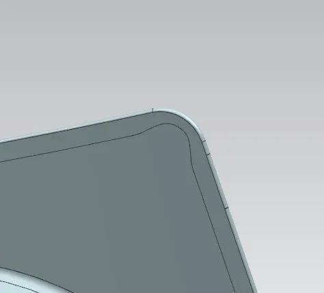
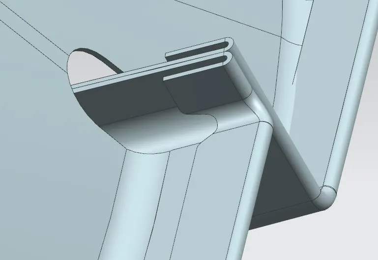
In the outer pannel; we have given reliefs on the region to avoid overlapping and folding.
reinforcement component
Reinforcement components are given in the area where joints like nut and bolt would provide.These will give additional strenght in joining area.The reinforcement material would be a rubberly material.The grey parts are reinfocement parts. We use reinforcement in hinge joint area,gas stray area,whiper mounding area and striker emboss area.

And this is our final output for the back door