DC Motor Control
1. Run MATLAB demo ‘Speed control of a DC motor using BJT H-bridge’. Modify the model such that armature current doesn’t shoot up when motor changes direction from forward to reverse.
Solution:
BJT
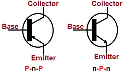
The Bipolar Junction Transistor is a semiconductor device which can be used for switching or amplification.
Transistors are three terminal active devices made from different semiconductor materials that can act as either an insulator or a conductor by the application of a small signal voltage. The transistor’s ability to change between these two states enables it to have two basic functions: “switching” (digital electronics) or “amplification” (analogue electronics).
There are two basic types of bipolar transistor construction, PNP and NPN, which basically describes the physical arrangement of the P-type and N-type semiconductor materials from which they are made.
The Bipolar Transistor basic construction consists of two PN-junctions producing three connecting terminals with each terminal being given a name to identify it from the other two. These three terminals are known and labelled as the Emitter ( E ), the Base ( B ) and the Collector ( C ) respectively.
BJT H-Bridge
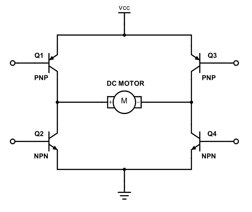
Now, sped control of DC motor using BJT H-Bridge
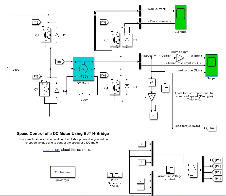
The H-bridge consists of four BJT or Diode pairs. Two transistors are switched simultaneously: Q1 and Q4 or Q2 and Q3. When Q1 and Q4 are fired, a positive voltage is applied to the motor and diodes D2-D3 operate as free-wheeling diodes when Q1 and Q4 are switched off. When Q2 and Q3 are fired, a negative voltage is applied to the motor and diodes D1-D4 operate as free-wheeling diodes when Q2 and Q3 are switched off.
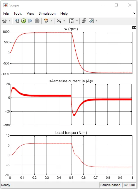
As we can see when voltage is applied to the armature, at positive half of the cycle and also when the voltage is reversed the armature current shoots up.
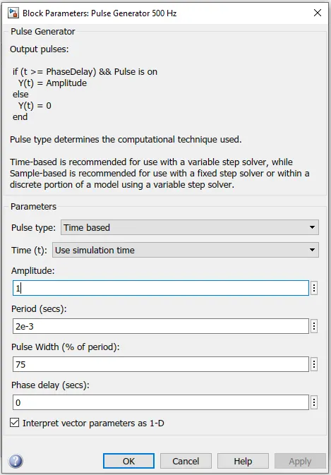
So we need to modify the pulse generator in order to get stable current in armature, ie
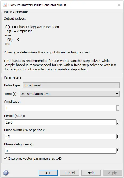
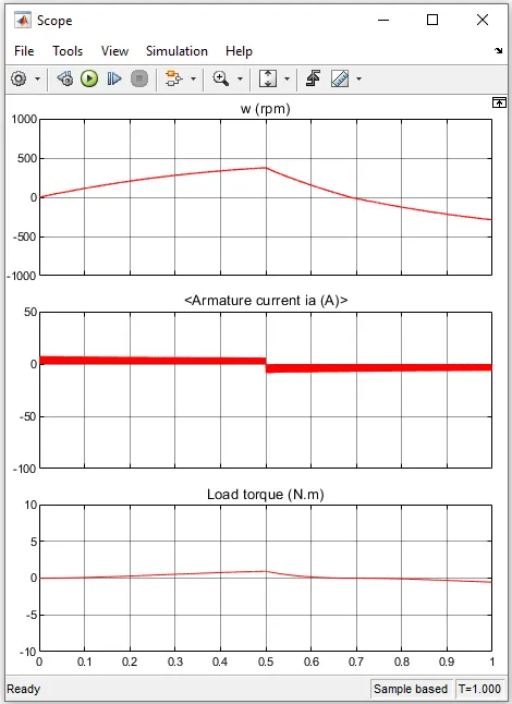
By changing duty cycle to 45% from 75% the armatuer current is clearly more stable than default results. The current in the armature does not shoot up or show fluctuations even voltage is reversed.
2.Refer to help section of ‘The Four-Quadrant Chopper DC Drive (DC7) block’. Compare it with H-bridge model.
Solution:
4 Quadrant Operation of a DC motor
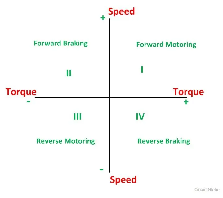
In the I quadrant power developed is positive and the machine is working as a motor supplying mechanical energy. The I (first) quadrant operation is called Forward Motoring. II (second) quadrant operation is known as Braking. In this quadrant, the direction of rotation is positive, and the torque is negative, and thus, the machine operates as a generator developing a negative torque, which opposes the motion.
The kinetic energy of the rotating parts is available as electrical energy which may be supplied back to the mains. In dynamic braking, the energy is dissipated in the resistance. The III (third) quadrant operation is known as the reverse motoring. The motor works, in the reverse direction. Both the speed and the torque have negative values while the power is positive.
In the IV (fourth) quadrant, the torque is positive, and the speed is negative. This quadrant corresponds to the braking in the reverse motoring mode.
| Function | Quadrant | Speed | Torque | Power Output |
|---|---|---|---|---|
| Forward Motoring | I | + | + | + |
| Forward Braking | II | + | - | - |
| Reverse Motoring | III | - | - | + |
| Reverse Braking | IV | - | + | - |
The Four-Quadrant Chopper DC Drive
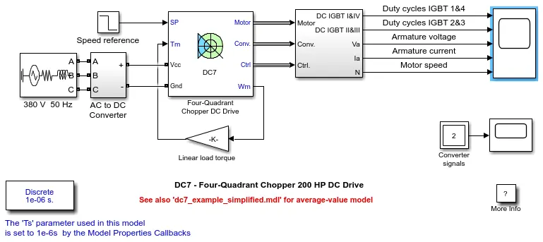
The 200 HP DC motor is separately excited with a constant 150 V DC field voltage source. The armature voltage is provided by an IGBT converter controlled by two PI regulators. The converter is fed by a 515 V DC bus obtained by rectification of a 380 V AC 50 Hz voltage source. In order to limit the DC bus voltage during dynamic braking mode, a braking chopper has been added between the diode rectifier and the DC7 block.
The first regulator is a speed regulator, followed by a current regulator. The speed regulator outputs the armature current reference (in p.u.) used by the current controller in order to obtain the electromagnetic torque needed to reach the desired speed. The speed reference change rate follows acceleration and deceleration ramps in order to avoid sudden reference changes that could cause armature over-current and destabilize the system. The current regulator controls the armature current by computing the appropriate duty ratios of the 5 kHz pulses of the four IGBT devices (Pulse Width Modulation). For proper system behaviour, the instantaneous pulse values of IGBT devices 1 and 4 are opposite to those of IGBT devices 2 and 3. This generates the average armature voltage needed to obtain the desired armature current. In order to limit the amplitude of the current oscillations, a smoothing inductance is placed in series with the armature circuit.
Simulation:
Before starting the simulation, set the initial bus voltage to 515 V via the GUI block ('Initial States Setting' button and 'Cbus' variable).
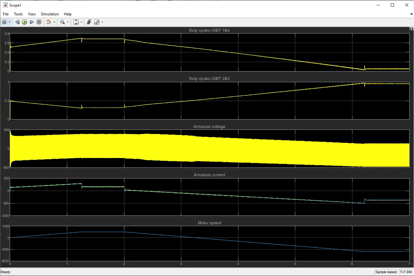
Start the simulation. You can observe the motor armature voltage and current, the four IGBT pulses and the motor speed on the scope. The current and speed references are also shown.
The motor is coupled to a linear load, which means that the mechanical torque of the load is proportional to the speed.
The speed reference is set at 500 rpm at t = 0 s. Observe that the motor speed follows the reference ramp accurately (+400 rpm/s) and reaches steady state around t = 1.3 s.
The armature current follows the current reference very well, with fast response time and small ripples. Notice that the current ripple frequency is 5 kHz.
At t = 2 s, speed reference drops to -1184 rpm. The current reference decreases to reduce the electromagnetic torque and causes the motor to decelerate with the help of the load torque.
At t = 2.2 s, the current reverses in order to produce a braking electromagnetic torque (dynamic braking mode). This causes the DC bus voltage to increase.
At t = 3.25 s, the motor reaches 0 rpm and the load torque reverses and becomes negative. The negative current now produces an accelerating electromagnetic torque to allow the motor to follow the negative speed ramp (-400 rpm/s). At t = 6.3 s, the speed reaches -1184 rpm and stabilizes around its reference.
Comparision with H-bridge
4 quadrant chopper have more control over the deceleration of the motor and can more accurately brake the motor. Where as H-bridge are also capable of braking operation without using friction or air or physical brakes to bring the motor to hault. 4 quadrant DC choppers are more commonly used in robotics and electro-mechanical devices.
4 quadrant choppers reduces the risk of current spikes while braking which potentially dameges the motor running at high speed.
4 quadrant choppers are more efficient due to less energy is wasted in the form of heat.
unlike 4 quadrant dc choppers H-bridge are not capable of regenerative braking, which makes 4 quadrant choppers ideal for hybrid eVs.
Finally, in 4 quadrant DC choppers a PI controller is used to control the speed and the current in the H-bridge this is not implemented.
3. Make a suitable EV model using DC7 block and make result report.
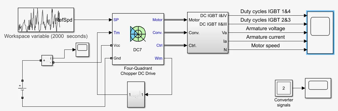
Modifications made to model:
1.Drive cycle
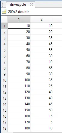
The drive cycle data is created in spradsheet and is imported into MATLAB
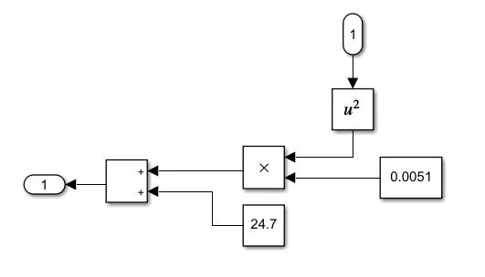
2.Speed-troque relation
T=24.7+0.0051ω2T=24.7+0.0051ω2
3.Power source
here, AC source is replaced with DC source and voltage levels are applied as per the requirments.
Electric vehicle model:
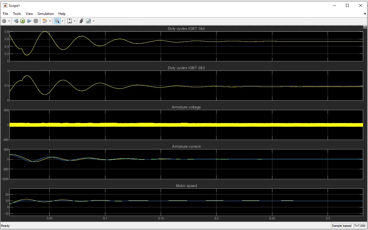
Results:
click the link below for drive cycle data sheet
https://docs.google.com/spreadsheets/d/1b5-J-iHliUtFUtt43sFG_IQV2JMmjPK-44UE66QxEVc/edit?usp=sharing