D.C. Motor Control
Aim –
- Run a MATLAB demo ‘Speed Control of a D.C. Motor using BJT H - Bridge’ modify the model such that armature current doesn’t shoot up when motor changes direction from forward to reverse.
- Refer to help section of the ‘Four Quadrant Chopper D.C Drive (DC7) Block’ compare it with H –Bridge model.
- Make a suitable model using DC7 Block and make result report.
Introduction –
Power BJT -
BJT H Bridge (Bi Polar Junction Transistor) it uses 2 n type semiconductors and 2 p type semiconductors connected together forming H bridge with motor in between to control the speed and direction of a D.C motor. Diodes are connected in parallel with each transistor to allow passing of current in one direction.
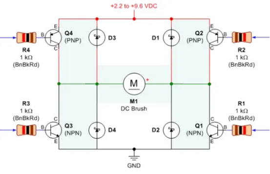
BJT H Bridge
Switch 1 & 4 are closed when motor needs to operate in forward direction.
Switch 2 & 3 are closed when motor needs to operate in reverse direction. These switches are controlled by signals from power electronic devices setup at particular time duration.
Power BJT H is a three terminal device with very large current and power handling capacity and offer high voltage resistance in OFF state. The construction of power BJT is slightly different than normal logic transistor. It has extra lightly doped region (n-) called as collector drift region in addition to (base contact, emitter contact and collector contact with N, P & N Region depending upon configuration of BJT).
Transistor –
a transistor is a miniature electronic component that can do different jobs. It can work amplifier or a switch.
When it works as an amplifier, it takes in a tiny electric current at one end (an input current) and produces much bigger electric current (an output current) at the other. In other words, it’s a kind of current booster.
Transistors can also work as switches. A tiny electric current flowing through one part of transistor can make much big current flow through another part of it. In other words, the small current switches on the larger one. This is essentially how computer chips work.
Power MOSFET –
It is a type of MOSFET which is specially meant to handle high levels of power. These exhibit high switching speed and can work much better in comparison with other normal MSOFET in the case of low voltage levels. However, its operating principle is similar to that of any other general MOSFET. Powe0r MOSFET are ore generally used in the n – channel enhancement mode or P- channel enhancement mode or n-channel depletion mode in nature.
IJBT –
IJBT (Insulated Gate Bipolar Transistor) constituted of BJT (Bipolar Transistor) and MOS (Insulated Gate Field Effect Transistor) composite full controlled type voltage driven power semiconductor devices with high input impedance MOSFET & GTR’s Low on State voltage drop down. GTR saturation pressure drop, carrier high current density but the drive current is large; MSFET drive power is very small, fast switching speed but large conducting voltage drop, the carrier density is small.
IGBT combines advantage of these two devices, the driving power is small and saturation while voltage drop is low. Very suitable for DC Voltage of 600V& above - Variable flow is AC Motor, Inverter, Switching power supply, lightning circuits, traction drive and other circuits, traction drive and other fields.
IGBT is the youngest one of high voltage switch family. A 15 Volt high impedance voltage source facilitate control current flow through the device which can achieve a lower control power to control the high current.
Comparison –
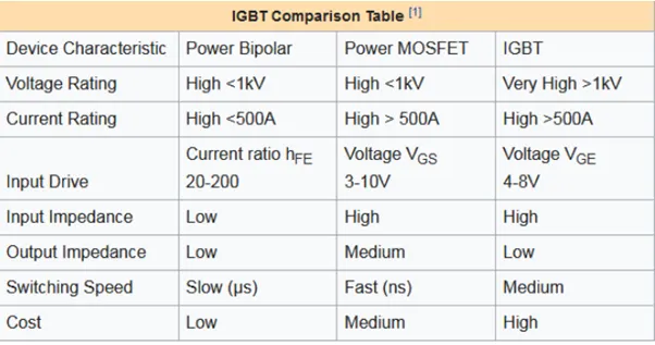
Speed control of D.C. Motor using BJT-H Bridge –
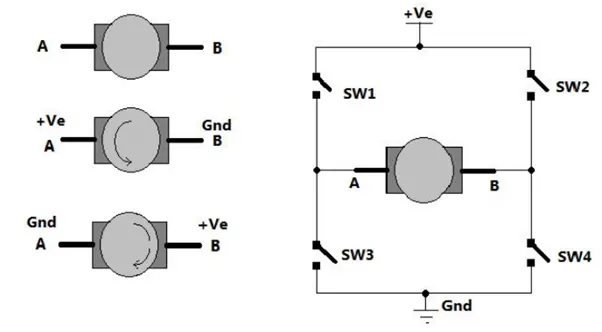
As shown in above figure there are two terminals ‘A’ & ‘B’ of a D.C. motor. Now if we connect terminal A with positive supply and terminal B with negative supply or ground then, the current will flow from motor from A to B and motor will rotate in one direction –say clockwise (CW) or forward direction now as shown in the second figure we have changed supply terminals. Now B is connected with Positive and A is connected to the ground. The current will flow from the motor from B to A and motor will rotate in one direction (Counter clockwise CCW – Reverse Direction).
The arrangement is shown in right side of figure. Four switches are connected in between positive supply and ground and DC motor is connected between two switches as shown. Such circuit arrangement is known as H –bridge because it looks like letter H (H bridge circuits are mostly used in DC motor drivers).
If SW 1 & SW 4 are passed simultaneously then the current will flow from +VE SW 1 - A – B –SW 4 – Gnd. So motor will rotate in one direction. Open (release) SW 1 AND SW 4 to stop the motor. Now if SW 2 & SW 3 to stop motor. Now if SW 2 & SW 3 are pressed so current will flow from +VE SW – B – A –SW 3 – Gnd. So motor will get reverse supply and it will rotate in another direction.
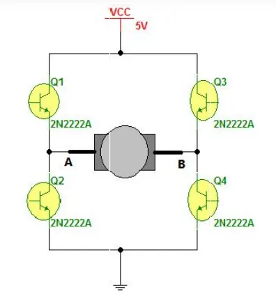
The circuit replace the switches with NPN type transistors. We all know that transistor works as switch, for NPN Transistor if we get +VE input to base it will turn ON and if we give 0 Input it will be turned OFF.
So in this circuit if Q 1 & Q 4 are turned ON simultaneously the motor will rotate forward and if Q2 & Q3 are turned ON then motor will rotate reverse.
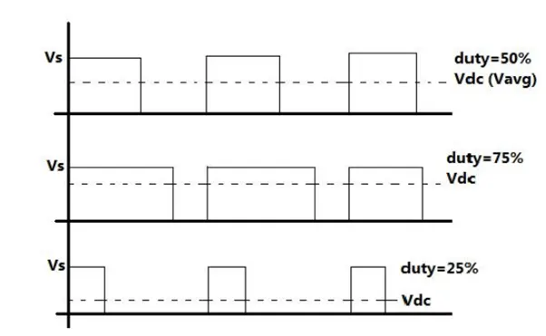
Now let us move the to vary the speed of D.C. Motor. The D.C. Motor speed varies as applied input voltage varies. as you increase applied voltage the speed will increase and vice versa. Applying max rated voltage will rotate motor at full speed (don’t apply max. rated voltage to motor otherwise motor windings may get burnt).
One of the popular methods for generating variable D.C. voltage is pulse width modulation (PWM).
Pulse Width Modulation means varying the width (duty) of pulse. Width means ON time Ton of pulse. The average output voltage (VD.C. / Vavg.) is given by equation-
VD.C. = [Ton / (Toff + Ton] * Vs.
Its directly given by TON. As shown in above figure if duty is 50% the average output voltage Vdc is exactly the half of Vs. if duty is increased to 75% Vdc also increases to 3/4th of the Vs & if duty is decreased to 25% Vdc reduces to 1/4th of Vs. thus are pulse width varies the average output voltage varies. So we have to apply PWM to D.C motor to vary its speed.
Simulation –
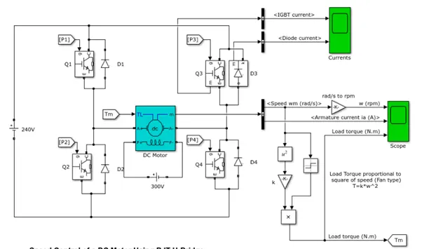
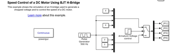
The motor starts in the positive direction with a duty cycle of 75% (Mean D.C voltage of 180V) at t = 0.5 seconds and the armature voltage is suddenly reversed and the motor runs in the negative direction.
Scope shows motor speed, armature, current and load torque and currents shows currents flowing in BJT Q3 and diode D3.
The block has two values of display as output. One is current output for IGBT & the diode current and the other is the scope for the values of the D.C. motor. The values of D.C. motor include –
- Speed (RPM).
- Armature Current (in AMPS).
- Load Torque (N-m).
The output values are as follows-
- IGBT current.
- Diode Current.
The IGBT block doesn’t simulate the GATE current controlling BJT / IGBT. The switch is controlled by the Simulink signal (1 / 0). The D.C. motor uses the present model (5 HP, 24V, 1750 RPM). It simulates the fan type load (where load torque is proportional to square of speed). The armature mean voltage can be varied from 0 to 240 Volts when the duty cycle (Specified the Pulse – Generator Block) is varied from 0 to 100%.
The H – bridge consist of four BJT / Diode pairs (BJT simulated by IGBT models). Two transistors are switched simultaneously – Q1 & Q4 or Q2 & Q3. When Q1 & Q4 are fired, a positive voltage is applied to the motor and diodes D2 & D3 operate as freewheeling diodes when Q1 & Q4 are switched OFF. When Q2 & Q3 are fired, a negative voltage is applied to the diodes and to the motor and diodes D1 – D4 operate as freewheeling diodes when Q2 & Q3 are switched OFF.
The above Simulink model is run using default conditions we obtain the following input –
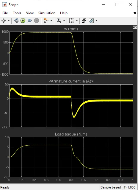
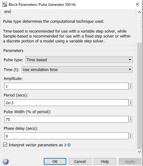
As we can see armature current is changing significantly so in order to control the variation of armature current, we have changed the duty cycle of the battery and observed the variation in armature current, pulse width reduces to 40%.
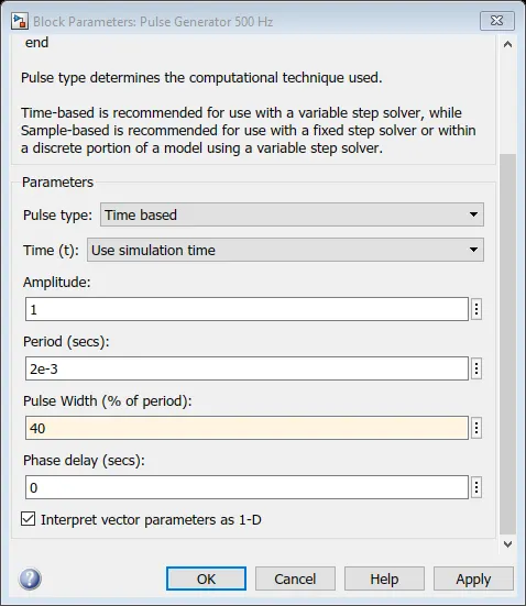
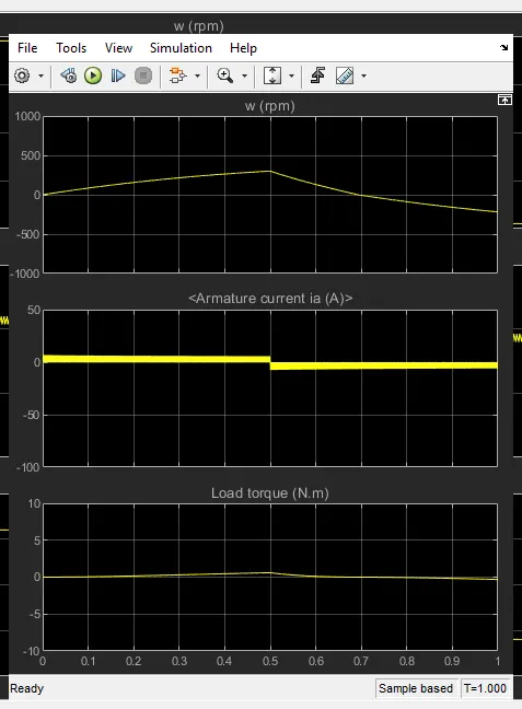
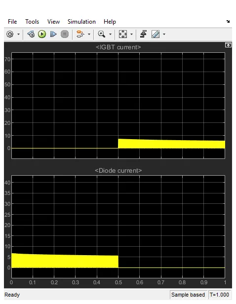
Armature current drops by reducing the duty cycle.
Reverse Modelling –
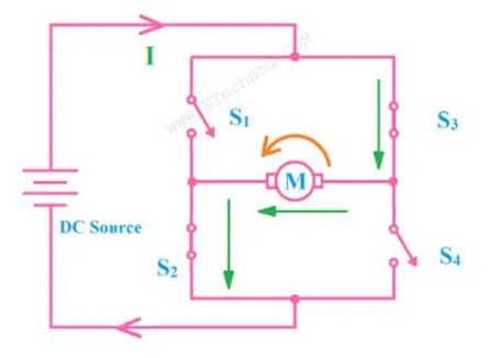
When S2 & S3 are fired negative voltage is applied to the motor which rotates ACW rotation the torque produced and armature current are negative value and diodes D1 & D4 operates s freewheeling diodes when S2 & S3 are switched OFF.
Forward Modelling –
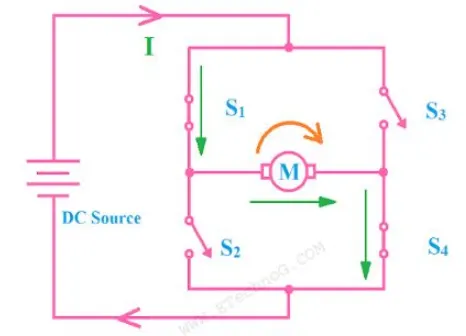
When S1 & S4 re fired positive voltage is applied to the motor which rotates in CW rotation to the torque produced. Armature current are positive value thus power is positive and diodes D1 & D3 operates as freewheeling diodes when S1 & S4 are switched OFF.
Q.2) The 4 Quadrant D.C. 7 Block –
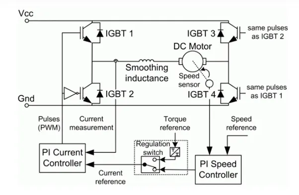
Fig. Four Quadrant Chopper Circuit.
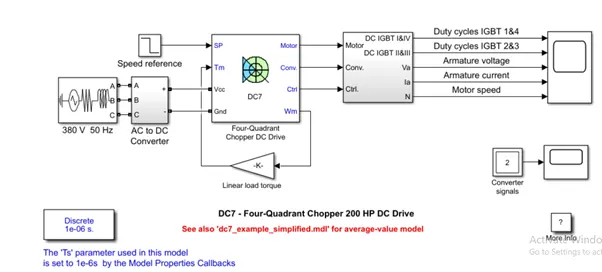
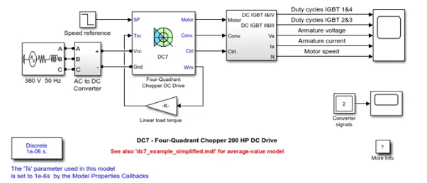
The 200 HP DC Motor is separately excited with 150 V DC filed voltage source. The armature voltage is provided by an IGBT converter controlled by 2 PI regulators. The converter is fed by a 550 V DC bus operator obtained by rectification of 380 V AC 50 Hz. Voltage source. In order to limit the DC bus voltage during dynamic breaking mode, a braking chopper has been added between the diode rectifier and the DC7 Block.
The first regulator is a speed regulator, followed by a current regulator. The speed regulator outputs the armature current reference (in p.u.) used by current controller in order to obtain electromagnetic torque needed to reach the desired speed. The speed reference change rate follows acceleration and deceleration ramps in order to avoid sudden reference changes that could cause armature over current and destabilize the system. the current regulator controls the armature current by computing the appropriate duty ratios of the 5KHz pulses of the 4 IGBT devices (Pulse Width Modulation). For proper system behaviour, the instantaneous pulse values of IGBT devices 1 & 4 are opposite to those IGBT devices 2 & 3. This generates the average armature voltage needed to obtain the desired Armature current, in order to limit the amplitude of the current oscillation, a smoothing inductance is placed in series with the armature circuit.
Comparison with H –Bridge Model –
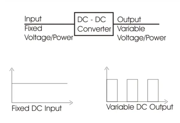
Chopper is basically static power electronic device which converts the fixed DC voltage / power to variable DC voltage / power. It is nothing but a high speed switch which connects and disconnects the load from source at high rate to get variable or chopped voltage at the output.
Devices used in chopper –
Low power application – GTO, IGBT power BJT, power MOSFET
High power application – Thyristor SCR.
Principle –
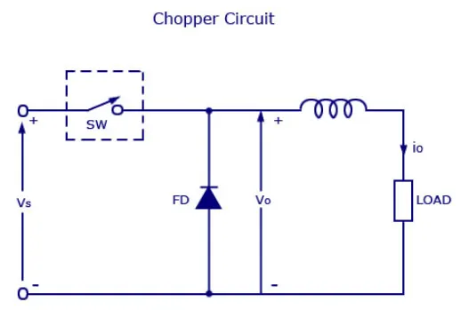
The chopper can be said as a high speed ON/ OFF semiconductor switch. Source to load connection and disconnection from load to source happen in a rapid speed. Consider a figure, here a chopped load voltage can be obtained from a constant DC supply voltage which has Magnitude Vs. chopper is represented by SW inside the dotted square which can be turned ON or OFF as desired.
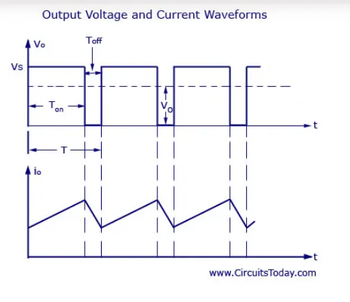
Let us now take a look of the output current and voltage wave forms of a chopper. During the time period Ton, the chopper is turned ON and the load voltage is equal to source voltage Vs. during the interval Toff the chopper is OFF and the load current will be flowing through the freewheeling diode FD & the load voltage is therefore zero during Toff . thus a chopped DC voltage is produced at the load terminals and we can see from the graph that the load current is continuous, during the time period Ton, load current rises during Toff load current delays.
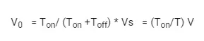
So we know that, load voltage can be controlled by varying the duty cycle.
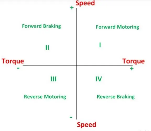
The four quadrant operation of any drives or DC motor means that the machine operates in four quadrants. They are Forward Braking, Forward Motoring, Reverse Motoring & Reverse Braking. The motor operates in two modes – motoring and braking. The motor drive capable of operating in both directions of rotation and of producing both motoring and regeneration is called the four quadrant variable speed drive.
In Motoring Mode, the machine works as, a motor and converts electrical energy into mechanical energy supporting its motion. The motor can work in both forward and reverse direction, i.e. motoring and braking conditions.
The product of angular speed and torque is equal to the power developed by the motor. For multi- Quadrant operation of drives the following conventions about the signs of torque and speed are used. When the motor is rotated in the forward direction the speed of the motor is considered positive. The drives which operate only in one direction forward speed will be their normal speed.
In loads involving up & down motions the speed of the motor which causes upward motion is considered to be in forward motion. For reversible drives, forward speed is chosen arbitrarily the rotation in the opposite direction gives reverse speed which is denoted by a negative sign.
The rate of change of speed positively in the forward direction or the torque which provides acceleration is known as positive motor torque. In the case of retardation, the motor torque is considered negative. Load torque is opposite to the positive motor torque in the direction.
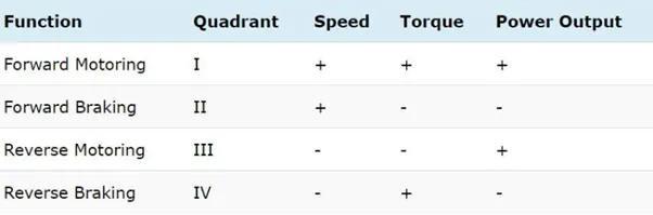
In the I Quadrant power developed is positive and machine is working as a motor supplying mechanical energy. The first quadrant operation is called Forward Motoring. II Quadrant is called Braking. In this quadrant the direction of rotation is positive and the torque is negative and thus the machine operates as the generator developing a negative torque which opposes the motion.
The kinetic energy of the rotating parts is available as electrical energy which is supplied back to the mains. In dynamic braking energy is dissipated in the resistance. The III Quadrant operation is known as reverse motoring. The motor works in the reverse direction. Both the speed and torque have negative values while the power is positive.
In the IV Quadrant the torque is positive and the speed is negative. This quadrant corresponds to braking in the reverse motoring mode.
Applications of 4 Quadrant operation –
Compressor, Pump, and fan type load requires operation in the I Quadrant only. As their operation is unidirectional, they are called one drive quadrant systems and the Transporter drive requires operation in both directions. If the regeneration is necessary application of all four quadrants may be required, if not then operation is restricted to quadrants I & III & thus dynamic braking / mechanical braking may be required.
The 4 Quadrant operation and its relationship to speed, torque and power output is summarized below in the table –
Comparison of 4 Quadrant DC7 Chopper block vs. DC motor BJT – H Bridge Block-
- Regenerative braking is possible.
- The current values are chopped but not continuous hence simulation takes less time.
- It is widely used in Automobile to control DC Motor speed and direction.
- To change the direction pf motor current signals are interrupted with one another.
DC Motor BJT – H Bridge Block –
- Regenerative braking isn’t possible but dynamic braking can be achieved.
- The current values are continuous.
- It is widely used in Robotics & Electro – Mechanical Device to control D.C. Motor speed and direction.
- To change the direction of the motor only polarity of the current is changed.
Overall in Automobile sector 4 – Quadrant chopper is preferred due to its high efficiency and ability to do regenerative braking which charges the battery whenever brakes are applied.
EV Model using DC7 Block-
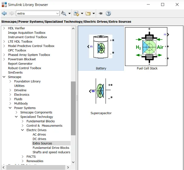
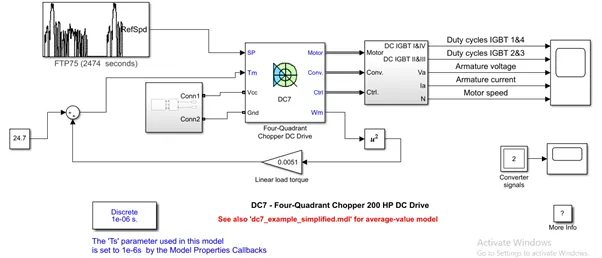
In order to build an EV using this block we will have to introduce the battery which is essential for the power supply. The battery can be created by the following model –
Library > Simscape / Electrical / Specialized Power Systems / Electric Drives / Extra Sources
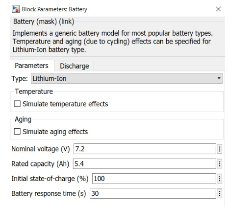
The battery setting will be kept at default as shown below-
In this model the speed converter block is replaced by a drive block. The drive cycle is used FTP75 drive cycle. For the simulation we also change the sampling time. There were many comparisons that were made with the original block of the DC7 Motor.
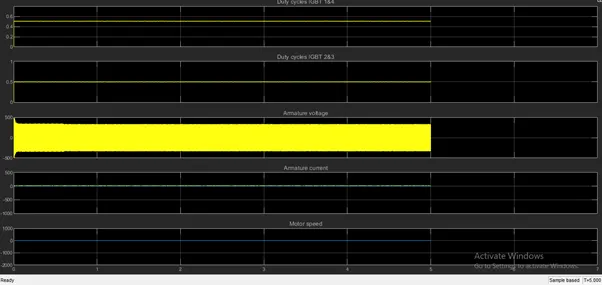
We can see that the values of the drive have changed once the drive cycle was added. The drive cycle has stabilized a bit more since we simulated on the drive cycle. The duty cycle has also changed and reduced to 12 % of the drive.
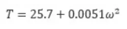
Torque motor equation applied to a block is given as –
As seen from the graph output, Yellow & Blue graph represents driving cycle and motor speed respectively.
Both curves match significantly so we can conclude our model is designed correctly.