D.C. MACHINE CHARACTERISTICS.
PROJECT NAME – D.C. MACHINE CHARACTERISTICS.
AIM –
- Develop a MATLAB code for D.C. Machine and visualize its speed and torque characteristics.
- Distinguish between cables used in wiring HEV.
- Brief on High and Low voltage in EV.
OBJECTIVES –
- We are plotting the speed vs. torque curve in MATLAB.
- Study on the usage of power and signal cabels.
- Study on low and high voltage in EV.
INTRODUCTION –
The D.C. Machine can be classified into 2 types namely D.C. Motor as well as D.C. Generator. Most of the D.C. Machines are equivalent to A.C. Machines because they include A.C. Currents as well as D.C. Voltages in them. The output of the D.C. Machine is D.C. output because they convert A.C. Voltage to D.C. Voltage. The conversion of this mechanism is known as the commutator; thus these machines are also named as commutating machines. D.C. machine is most frequently used for a motor because the main benefits of this machine includes easy speed generation as well as torque generation. The application of the D.C. Machine is limited trains, mills and mines.
for examples - trolleys, underground subway cars may utilize D.C. Motors.
Also in the past automobiles were also designed with D.C. Dynamos for charging their batteries.
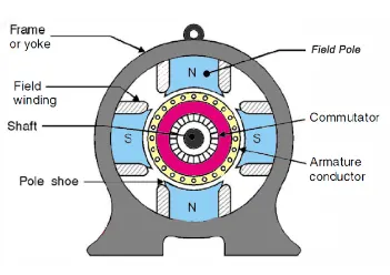
Schematic dia. For D.C. motor.
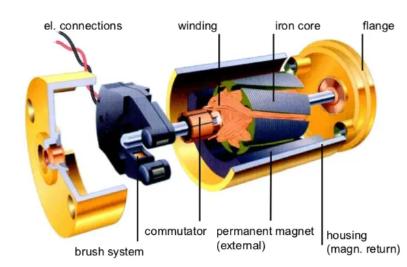
Cross sectional view of D.C. motor.
- What is D.C. Machine?
A D.C. machine is an electromechanical energy alteration device. The working principle Of D.C. machine is when electric current flows through a coil within a magnetic field, and then magnetic force generates a torque that rotates the D.C. motor.
Generally, three characteristics curve are considered important for D.C. motors which are –
- Torque vs. Armature current.
- Speed vs. Armature current.
- Speed vs. Torque.
Speed vs. Torque –

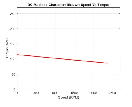
This characteristic is also called as mechanical characteristic. From above diagram it can be said that when the speed is high then torque is low and vice a versa.
The relationship between speed and load (or torque) is typically shown on the motor’s torque speed curve.
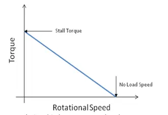
The inverse relationship between speed and torque means – increase in load/ torque on the motor will cause a decrease in speed. This can be demonstrated by D.C. motor torque equation.
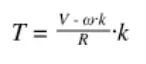
Where,
T = motor torque.
V = supply voltage.
= rotational speed.
K = motor constant.
R =- résistance.
The motor constant (K) doesn’t change, and résistance (R) in the motor windings is constant. Therefore, the supply voltage (V) is constant, and torque (T) is inversely proportional to speed (`omega`)
Rearranging for speed, we can see the same inverse relationship to torque,
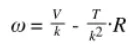
The inverse relationship means the torque speed curve have a descending line, with negative slope. The torque speed curve begins at the crossing of the y-axis where torque is max. and speed is zero. This is stall torque – the max. torque when the motor is running at a nominal voltage. The curve slopes downward until it intersects the x-axis, i.e. zero torque and maximum speed. This point is known as no load speed. (The speed when running at nominal voltage and zero loads). As the torque speed curve is a straight line so it is simple to find the torque of the motor produced at a given speed, or conversely to find the motor’s speed for a given load (torque) on the shaft.
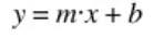
Where,
y = y- axis variable
m = slope of the line.
x = value of x-variable.
b = point at which line crosses y-axis (y-intercept).
Using this equation for torque speed curve we can find motor’s torque at given speed. In this case the variables in the line equation represent the following.
y = torque to be determined.
m = change in torque.
x = given speed.
b = tall torque (value where the line crosses the y- axis).
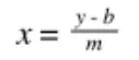
this line equation can also be rearranged to find motor’s speed at a given torque.
clear all
close all
clc
% Motor speed (RAD/SEC.)
Speed = linspace(0,250,75);

% Constant motor speed (RPM/V)
N = input('Motor Speed Value - ');

% voltage supply (VOLTS.)
V = input ('Supply Voltage - ');

% Resistence value of Armature (OHMS.)
Ra=input ('Armature resistance - ');

% Back EMF inputs
EMF = 1;

% To calculate motor constant
K = ((EMF*60)/(N*2*3.14));

% To calculate torque by using D.C Machine equation
T = ((V*K)/Ra) - (((K)^2/Ra)*Speed);

%To calculate total current
TC = (V-EMF)/Ra;

% To calculate the torque
T_max = K*TC;

% To Convert RPM TO RAD/S
Speed = Speed * (60/6.28);

% Plotting D.C. Machine characteristics w.r.t speed vs. torque
plot(Speed, T, 'color', 'b' ,'linewidth' , 3);
xlabel('Speed (RPM)');
ylabel('Torque (Nm)');
title( 'DC. Machine characteristics wrt Speed vs. Torque');
grid on
axis([0 2500 0 250]);
Q.2) How can you distinguish between power cables and signal cables?
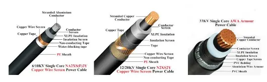
Power cables are basically electrical conductors that are held together in order to transmit electrical power on a large scale. It has many industrial applications that makes the wires popular choice to be used in ships, airports, industrial areas, commercial centres, hospitals and many more. When they are installed they can be exposed or buried deep within a ground or building. There are different sorts of power cables such as flexible cables which can be also used for mobile tools as well as heavy machinery.
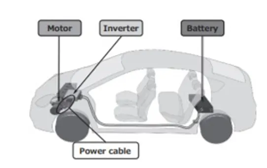
Power cables generally used to supply modern day electric applications at huge level, power cables connect the inverter with two 3 phase alternating present day (AC) vehicles, one used for driving the vehicles while other is used for producing energy. The power energy cables had been first used within Toyota Prius that launched in Dec. 2015.
Power cbales are generally of 2 types
- Six phase integral moulding.
- Copper cloth shield.
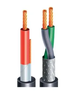
Signal cables are low power and currently rated wires whereas power cable is high current rated and power. Signal cables will have smaller gauge and individually shielded twisted pairs. Signal cables are not heavy enough to prevent too much voltage drop or cable overheating and damage when used in a control circuit. Control circuits usually be in the range of 1 to 5 amperes. These are flexible cables used in data transmission applications from one system to another which helps in signal protection. Signal cables are low power and currently rated wires. It consists of annealing material type conductor which may cool easily and remove internal stresses and toughness.
Signal cables are made up of metal wire or optical fibres which is used to transfer data. These cables are used in wire harnesses for various types of car doors opening and closing and for automatic locks. These are connected with electronic control units and used to transmit the signal to various parts of EV like powertrain unit, battery module, ABS etc. Signal cables are also used in dashboard instrumentation systems
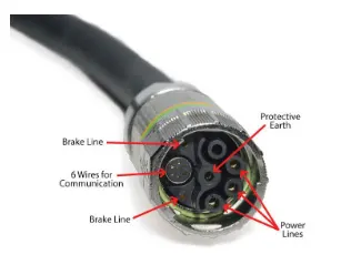
The main difference between these two is power cables are used for powering the motors, industrial machines, large power transmitting cables, signal cable are used for low and high analog signals such as RTDs, Filed instruments. Signal cables are used in test and measurement applications. If you are using 4 wire micro motion transmitter. Signal cable will carry 4 to 20 Ma signal and power cable will carry 24DC/ 110/ 230 Vac. Both cables cannot run on fixed route.
Q. 3) What Voltage levels are considered as high and low battery pack of an electric vehicle.
Generally, the voltage level is depending upon battery ampere rating & current rating. (Run time = Ah. Rating / Current Rating)
A battery pack that powers electric vehicles consist f individual battery cells and modules organised in series and parallel. A cell is smallest unit of battery, comprised of 4 key components including cathode, anode, electrolyte and separator.
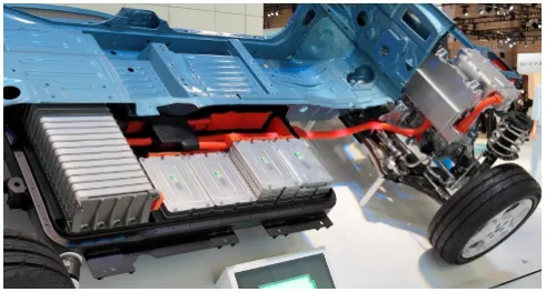
Current battery systems for hybrid and electric vehicles typically have operating voltages of 200- 800 volts. The most common type of battery used for electric and hybrid electric vehicles are lithium ion batteries (Li-Ion or Li –B). A common pack is composed of blocks of 18 to 30 parallel cells in series. The battery capacity in most EVs ranges between 16 KWh to 25 KWh. The cells of most electric BEVs are energy optimised whwere as HEVs use performance optimised cells.
Most common battery capacity ranges are as follows-
- Hybrid Vehicles – 0.5 to 2 KWh (100 to 200 Volts)
- Plug-in Hybrid vehicles – 4 to 20 KWh (100 to 200 Volts)
- Electric Vehicles – 30 to 100 KWh or more (Higher than 400 V to 800 V)
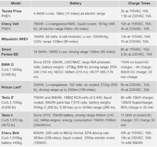
In terms of carbon footprint, the electricity used to charge the EVs should come from renewable energy resources. Published reports say that emissions from EVs powered by America’s electricity grids are higher than those from an efficient ICE. Table 2 illustrates common EVs.
The makers of Nissan leaf, BMW i3 and other EVs use proven Lithium Manganese battery with NMC (Nickel, Manganese, Cobalt) blend, packaged with prismatic cell . Tesla uses NCA (Nickel, Cobalt, Aluminium) in the 18650 cell that delivers the impressive specific energy of 3.4 Ah per cell or 248 Wh/Kg to protect Li- Ion battery from overheating during high speeds, Tesla oversize the battery pack by magnitude of three or four folds compared to other EVs. The large 90 KWh battery of Tesla Model S (2015) provides an unparalleled driving range of 265 miles, the weight of the battery is 540 Kg and this increases the energy consumption to 238Wh/Km, one of the highest among EVs.
In comparison, the BMW i3 is one of the lightest EVs and has low energy consumption of 160 KW/km. the car uses LMO/NMC Batteries that offer moderate sp. Energy of 120 Wh/kg but it is very rugged. The 22 KWh hour battery pack provides driving range of 130 to 160 Km, to compensate for the shorter range the i3 offers REX, an optional gasoline engine fitted on the back.
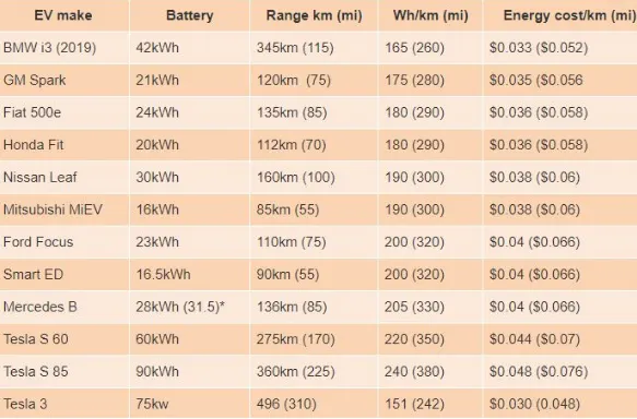
Estimated energy consumption and cost per km/mile of common EVs.
CONCLUSIONS –
- Implemented D.C. machine torque speed characteristics equations using MATLAB Program.
- Distinguished between power cables and signal cables of an electric vehicles.
- What voltage levels are considered as high and low battery pack of an electric vehicle.
REFERENCES-
- https://www.electricaleasy.com/2014/07/characteristics-of-dc-motors.html
- https://www.motioncontroltips.com/torque-equation/#:~:text=DC%20motors%20are%20relatively%20simple,the%20load%20on%20the%20motor.&text=Therefore%2C%20when%20supply%20voltage%20(V,proportional%20to%20speed%20(%CF%89).
- https://www.windpowerengineering.com/single-cable-power-signals-now-servo-drives/
- https://www.slideshare.net/vguardindustries/the-main-differences-between-power-and-control-cables-a-primer-24376868
- https://www.allaboutcircuits.com/technical-articles/introduction-to-electric-vehicle-battery-systems/#:~:text=Common%20nominal%20pack%20voltages%20in,and%20mass)%20of%20copper%20cable.