Cyclone Separator Challenge
Aim: To simulate particle flow in a cyclone separator, and calculate the separation efficiency and pressure drop.
Introduction and theory:
The flow of particles within a geometry poses an interesting problem, as there are many different forces acting upon it at an instant of time. The unique behaviour particles within a gas-stream can be taken advantage of in a few ways. One of the interesting applications of this behaviour, is the cyclone separators. A cyclone separator is used to separate large dust particles from the gas stream, using the physics of the particles present in the gas-stream to separate it from the lighter gas. The separation effciency gives an understanding of how well the cyclone separator works for particles of a certain size, and is the primary metric used to determine the effectiveness of a cyclone separator. The particle size and the velocity of the particles have a profound impact on the efficiency of a particle separator, and this will be the main focus of this project. There are empirical models that were used to calculate the separation efficiency of a cyclone separator, and was a challenge to obtain when the technology for simulating this was not present. These empirical models were important, as the development and design of a cyclone separator were dependant on the results that these models would provide. These models will be discussed briefly in this project.
Simulation workflow:
Modelling and solving approach:
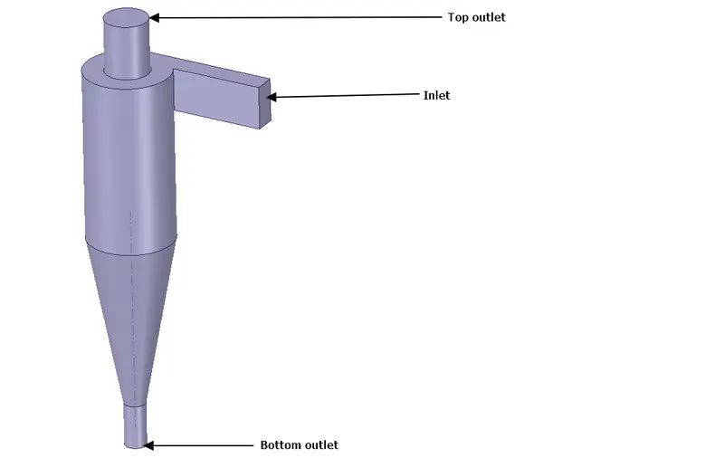
- For this case, the gas-stream will be entering the inlet, and the behaviour of the particles will be observed. A single inlet, and two outlets are present in the geometry. The outlet at the bottom of the cyclone separator will be used to collect the heavier dust particles, while the lighter gas will exit through the outlet at the top. The physics behind this will be explained in the results section.
- A tetrahedral mesh will be used for this simulation.
- The particle physics within the cyclone separator is complex, and normal fluid simulation methods will be unable to simulate this. In this simulation, Discrete Phase modelling will be used to simulate the particle flow in the cyclone separator. Discrete phase modelling solves the trajectory equations for the particles, and solves the equations related to the forces acting upon the various particles flowing through the cyclone separator. Within this model, turbulence is taken into account by using a Cloud particle tracking or Schocastic tracking. The difference between the two is that the cloud particle tracking method computes the mean trajectory of the particles in a group, while the other method computes the trajectory values by integrating the equations, using the instantaneous velocity. These methods are used to compute dispersion of the particles due to turbulance, and are required for this simulation. There are other methods under Discrete modelling that are used for various other phenomena taking place. That being said, DPM will allow us to simulate the physics of the particles in the cyclone separation.
- An RNG k-epsilon model will be used for the particle flow within the cyclone separator. This particular model has been used as it takes the swirl in the flow into account. This is an important factor in the selection of the model, as the flow is swirl-dominated. It is also known to provide accurate near-wall solutions.
The following workflow was used to simulate the flow in a cyclone separator.
1) Geometry creation:
- The cyclone separator geometry was created in SpaceClaim.
- In order to obtain the fluid volume present within the interior of the cyclone separator model, the 'Volume Extract' command was used. The edges of the inlet, and the two outlets were selected(Prepare > Volume Extract).
- After the fluid domain was created, the solid volume was suppressed, as only the fluid domain is to be observed.
- This model was then imported for meshing.
- The following image displays the goemetry used and created in SpaceClaim.
2) Mesh details:
Mesh configuration:
- For this simulation, a tetrahedral mesh was chosen by entering Project > Model > Mesh > Defaults > Element size.
- The element size was set as 9 mm.
- The named selections were provided by highlighting the faces and entering the required name. The mesh and the named selections have been displayed below.
| Mesh | 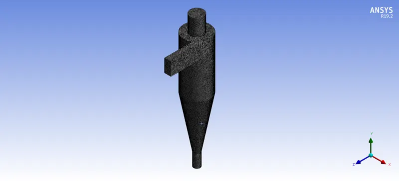 |
| Inlet | 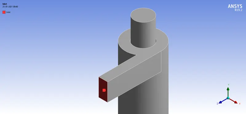 |
| Top outlet(Outlet-1) | 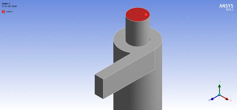 |
| Bottom outlet(Outlet-2) | 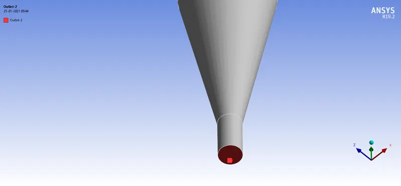 |
3)Fluent setup:
(I) General settings:
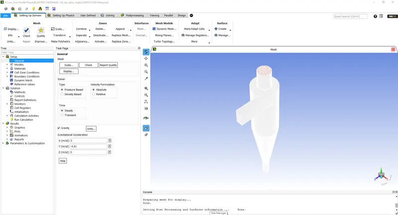
- The simulations that are going to be carried out are steady state in nature. This is set in the General section(Setup > General). Acceleration due to gravity is switched on as well, and a value of -9.81 `m/s^2` is given, with the negative sign indicating the downward direction.
Solver used: Pressure-based solver
A pressure-based solver is used for this case, as the compressibility effects are to be neglected. A density-based solver is highly accurate, but requires more computation time, and would not prove advantageous in this case. A pressure-based solver requires less computational time, and will provide accurate simulation results for this case. The pressure-based solver solves the governing equations in a sequence, unlike the density based solver.
Model settings:
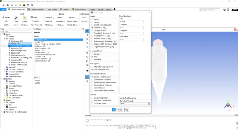
Model used : RNG k-epsilon
- The model that will be used in this simulation is the RNG k-epsilon model. The reason behind the selection of this model has been mentioned in the Modelling and solving approach section. The RNG k-epsilon model introduces two analytically derived constants, mentioned in the RNG turbulence theory. The introduction of a swirl constant that modifies the value of the turbulent viscosity according to the degree of swirl present in the flow.
- This has been done by entering Setup > Models > RNG k-epsilon > Swirl.
(III) Discrete Particle modelling:
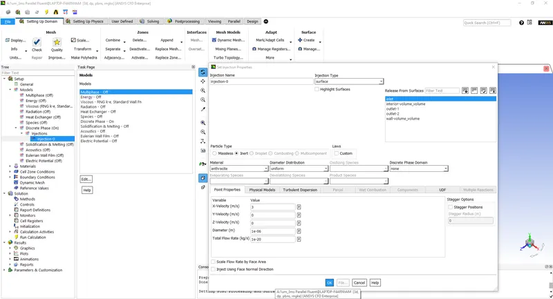
| `text(Particle velocities)`: | `text(1 m/s, 3 m/s, 5 m/s)` |
| `text(Particle diameters)`: | `1 mum, 3 mum, 5 mum` |
- The Interaction with continuous phase and Update DPM sources every iteration settings are switched on. The iteration interval is set as 10. The rest of the values are kept as the default values(Setup > Models >Discrete Phase > Injection).
- In this section, the solid particles that flow through the cyclone separator are defined, and are set as Anthracite. After setting the solid, the particle diameter and the velocity of the particles desired are set.
- Varying the diameter and the velocity will have an effect on the results, and this will be observed in the results section.
(IV) Boundary conditions:
- The freestream velocity is set to 1,3, and 5 m/s(according to the case) at the inlet by going into Setup > Boundary Conditions.
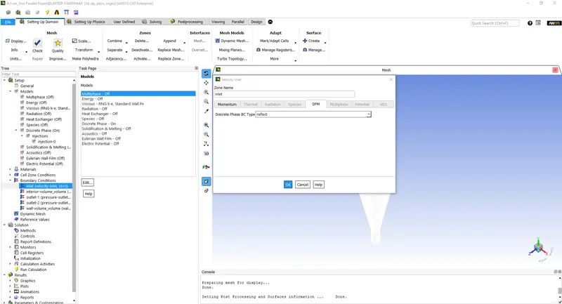
- The inlet and the wall boundary conditions are set to 'Reflect'. This will cause the particle to hit the wall, and bounce off of it.
- The outlet at the bottom is set to 'Trap', and will stop computing the physics of a particle that has reached it.
- The outlet at the top is set to 'Escape' , and will stop computing the physics of a particle that has reached it.
- The boundary conditions are set in Fluent, as shown in the table below.
-
Location Boundary condition Inlet Reflect Outlet-1 Escape Outlet-2 Trap Wall wall - The number of iterations is set to 700 by entering the value within the Run calculation section.
(V) Method and Initialization settings:
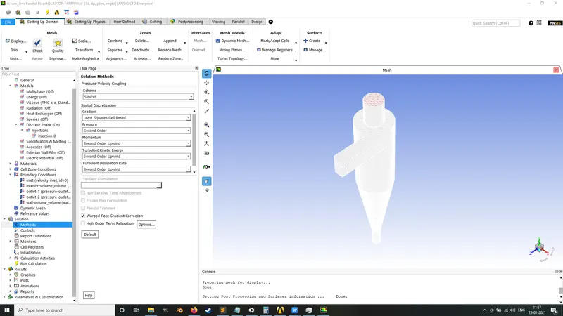
- The turbulent kinetic energy and dissipation equations are solved using Second order upwind schemes, which will provide solutions with an accuracy of the second order. This has been done by entering Solution > Methods.
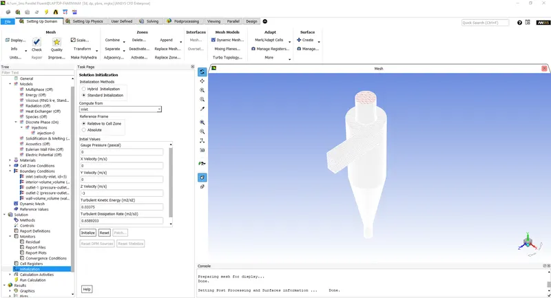
- The solution is initialized by using Standard initialization. This will allow us to begin computation at the inlet. This has been done by entering Solution > Initialization.
Results:
Empirical models used to compute separation efficiency:
i) Lapple model:
The Lapple model is one of the oldest models used to compute the separation efficiency of a cyclone separator. This model is simple, and takes a couple of liberties with the assumptions regarding the state of the particles at the inlet. The model assumes that the travels from 50 percent of the inlet width is collected with 50 percent efficiency. Another assumption made by the model is that the particles that enter are uniformly from the inlet. Both of these assumptions come with accuracy issues, and the separation efficiency obtained from this model are sub-standard at best.
ii) Leith and Licht model:
The Leith and Licht model computes the separation efficiency by assuming that the particles do not have changing radial acceleration, and there is no difference between the angular velocities of the gas and the particles. This model contains some discrepencies, as the model assumes that a particle that makes contact with a wall has escaped(depending on the residence time). Some of the assumptions that have been made contradict the main basis of the model, and the results obtained from this model are unreliable.
iii) Iozia and Leith model:
The Iozia and Leith model computes the separation efficiency by carrying out force balancing, taking into consideration the flow resistance of the particles within the separator and the centrifugal force acting upon them. The main contribution of this model to the improvement of cyclone separator efficiency calculations, was the improved empirical relation for the cut-size diameter. This is an important metric used to calculate the efficiency of the cyclone separator, and is defined as the particle size diameter for which the separation efficiency is 50 percent. This model proved to be superior to the models mentioned above, and a couple of other models at the time.
iv) Li and Wang model:
The Li and Wang model is the most complex of all of the empirical models, and takes into consideration the collision of the particles with the wall and turbulent diffusion. Turbulent diffusion is time dependent, and this adds to the complexity of the empirical relation. However, this empirical model computes highly accurate values of separation efficiency.
Particle diameter variation, with the particle velocities kept identical between cases:
Case I : `text(D) = 1 mum, text(v) = 3 m/s`
Case II :`text(D) = 3 mum, text(v) = 3 m/s`
Case III : `text(D) = 5 mum, text(v) = 3 m/s`
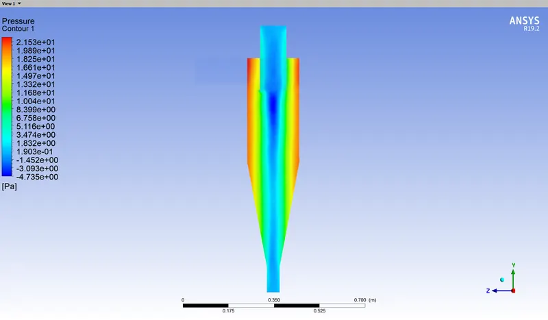
The following pressure contour will be used for reference. This plot will remain the same between the cases mentioned below, as there is no change in the inlet velocity. The inlet velocity plays an important role and influences pressure within the cyclone separator dramatically. This will be discussed in the next section.
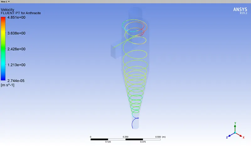
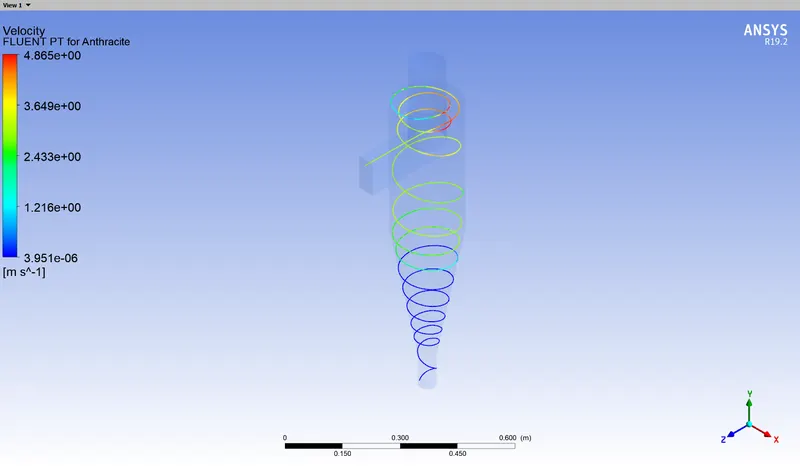
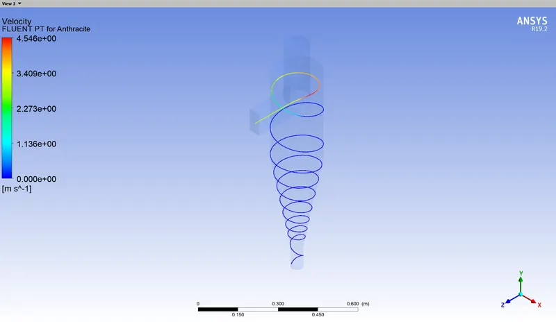
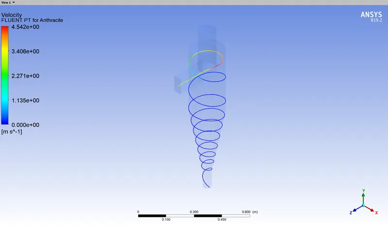
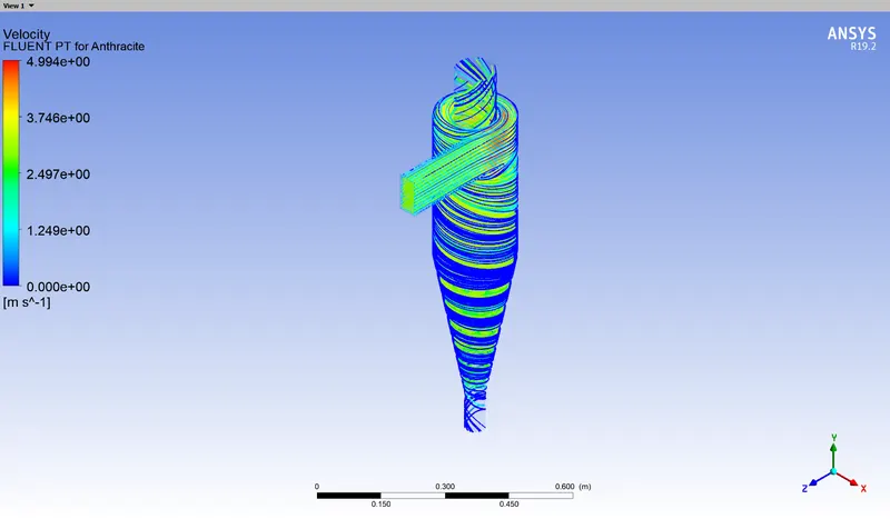
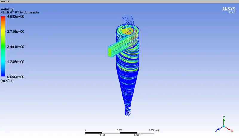
The following plots display specific tracked particles for different cases.
| Case I |
Case II | |
| Particle 2 | 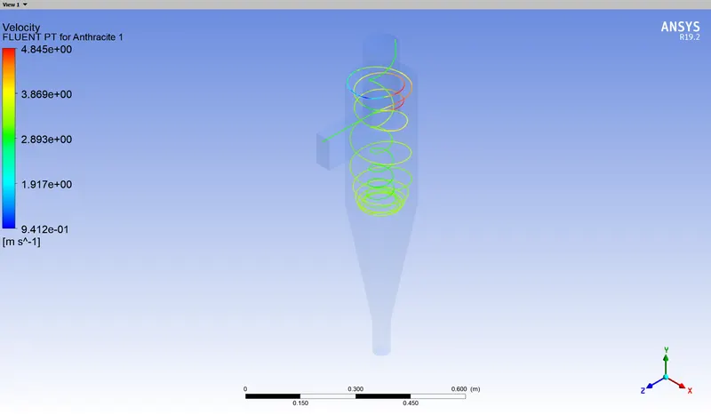 |
 |
| Case III | ||
 |
||
| Case I | Case II | |
| Particle 10 | 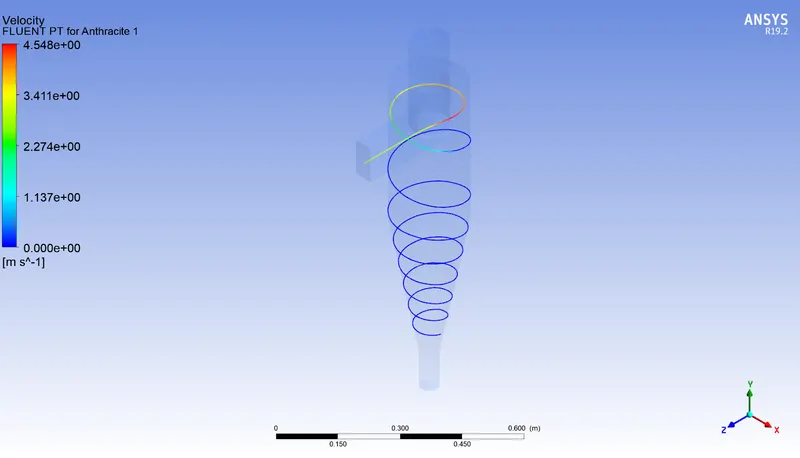 |
 |
| Case III | ||
 |
||
| Case I | Case II | |
| All particles | 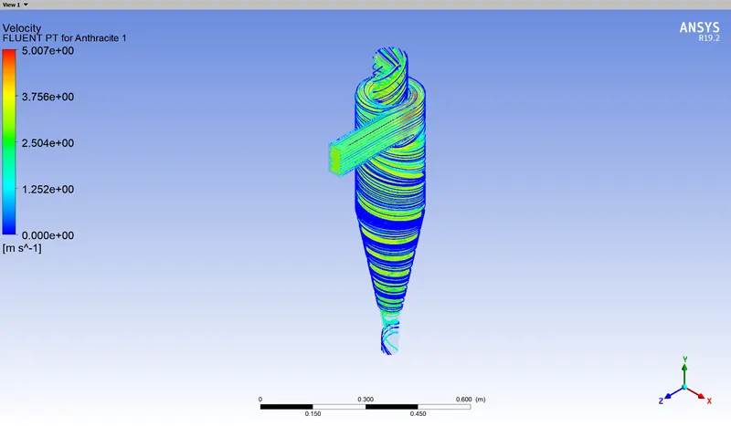 |
 |
| Case III | ||
 |
Console display :
Case I : `text(D) = 1 mum, text(v) = 3 m/s` :

Case II : `text(D) = 3 mum, text(v) = 3 m/s`:

Case III : `text(D) = 5 mum, text(v) = 3 m/s`:

From the plots shown above, a couple of conclusions can be drawn regarding the basic behaviour of the particles within the cyclone separator.
Observing the plot for particle 2 in Case I, it can be seen that the particle enters the cyclone separator, reaches around the mid-section of the separator, and ends up flowing upward, escaping instead of getting trapped. The primary objective is to collect these particles at the bottom outlet, and this goes against the requirement of a cyclone separator. The reason this occurs, is to do with the basic working of a cyclone separator.
If the pressure contour of the separator is observed, it can be seen that a low pressure zone exists at the center of the geometry. This occurs due to the pressure of the outlet being lower compared to the pressure present in the geometry, and the movement of the gas-stream within the separator. The movement of the stream creates a vortex at the center of the separator, and the low pressure zone dips below atmospheric pressure. This is where the primary working of a cyclone separator lies. The low pressure zone exerts a centripetal force on the air(gas) and the particles that it carries. The centripetal force acting on the air due to the low pressure zone, overcomes the inertia of the air, and the lighter gas is pulled toward the low pressure zone, and eventually, escapes through the top outlet. Particles present in the air however, have much higher mass compared to the gas. Since the particles are heavier, they should ideally not be affected by the low pressure zone, and the angular momentum of the particles is enough for them to overcome this centripetal force, and will eventually travel to the bottom outlet and get trapped.
The reason that the swirling of the air takes place, is because of the momentum the air carries coming from the inlet, and the low pressure at the center of the cyclone separator, pulling the air toward it.
The cylindrical shape of the separator tapers into a conical shape near the outlet, and this further promotes the effect. The wall will apply a force normal to it, and the wall is inclined. This forces the gas to separate from the particles, if the force exerted prior to this section was not adequate.
That being said, it should be noted that the angular momentum of a particle is heavily dependent on it's mass. Particle 2 with a diameter of `1 mum` and a velocity of 3 m/s, escapes the separator via top outlet. The main reason that this has occured, is because the particle is much lighter compared to the other two cases. The particle is too light to overcome the centripetal forces acting upon it, and enters the low pressure zone, exiting the separator through the outlet meant for the lighter gases. This suggests that this cyclone separator is not equipped to handle particles of this size, and will not effectively separate the particles from the gas stream. This can be seen in the results printed in the console display for this case. The number of particles that have escaped is 59, and this shows the ineffectiveness of the cyclone separator for particles of this diameter.
This issue is seen to a lesser degree in the case with a particle diameter of `3 mum` and a velocity of 3 m/s. Although the issue is still present in this case, the number of particles that have been trapped in the bottom outlet is markedly higher. There lies another issue related to particles of small diameter and mass, and this has been shown in the plot for Particle 10 with a diameter of `1 mum` and a velocity of 3 m/s. The particle does not leave either outlet, and seems to be in limbo. This phenomenon occurs when the particle has enough inertia to counteract the centropetal force, but does not have enough momentum to maintain it's course to the bottom outlet/trap. This happens in locations where the diameter of the cyclone separator reduces, around the cone area. The diameter reduction, and the lack of reduction in the velocity of the particle, causes it to continue rotating on the circumference of the cone. This causes the particle to rotate inside the cyclone separator, and is the highly undesirable. This is denoted by the 'incomplete' statement in the console display of the results. In a practical setting, this fate of this type of particle is determined by the movement of other particles in the system. If the console display of the results of the particle with a diameter of `1 mum` and a velocity of 3 m/s is observed, it is seen that there are 51 particles that were unable to escape, and remained in the system. This is highly unfavourable, and the effect of this is reduced as the mass and diameter of the particles increase.
The final set of plots shown for the movement of all of the particles, shows that the number of particles near the wall for Case III is much higher than Case I and Case II. The number of particles leaving the outlet in this case is much higher as well. This suggests that the particles with large diameters are more likely to get trapped, and possess the required inertia for movement towards the bottom outlet.
The best metric that can be used to measure how well a cyclone separator works, is the separation effciency. The formula for separation efficiency has been displayed below.
`eta_(text(separation)) =n_(text(trapped))/(n_(text(tracked))-n_(text(incomplete))`
where,
`eta_(text(separation)) = text(separation efficiency)`
`n_text(trapped) = text(number of particles trapped by the bottom outlet)`
`n_text(imcomplete) = text(number of particles in the separator)`
`n_text(tracked) = text(total number of particles that have been simulated)`
`text(D) = 1 mum, text(v) = 3 m/s` :
`eta_(text(separation)) = 32/(142 - 51) = 0.35164`
`text(D) = 3 mum, text(v) = 3 m/s`:
`eta_(text(separation)) =100/(142 - 1) = 0.7092`
`text(D) = 5 mum, text(v) = 3 m/s`:
`eta_(text(separation)) =136/(142 ) = 0.9577`
Observing the calculations shown above, it is clear that the particle size has a profound effect on the separation efficiency. In this case, as the particle diameter increases, the higher the likelihood that it it trapped at the bottom outlet.
Particle velocity variation, with the particle diameters kept identical between cases:
Case II : `text(Diameter) = 5 mum, text(velocity) = 1 m/s`
Case II : `text(Diameter) = 5 mum, text(velocity) = 3 m/s`
Case III : `text(Diameter) = 5 mum, text(velocity) = 5 m/s`
The following images display the pressure contours of the cases mentioned above:
| Case | Pressure contours |
| Case I | 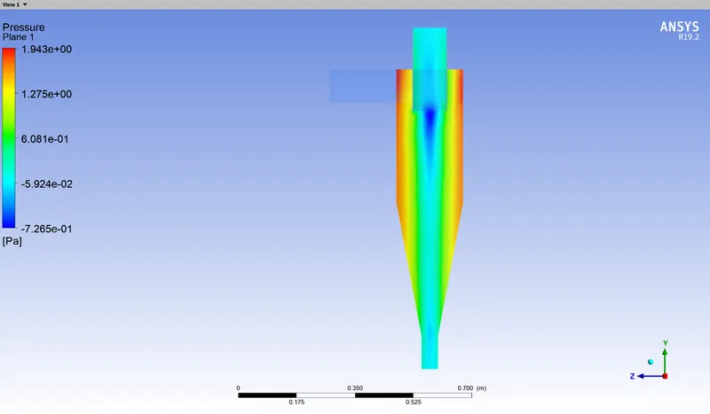 |
| Case II | 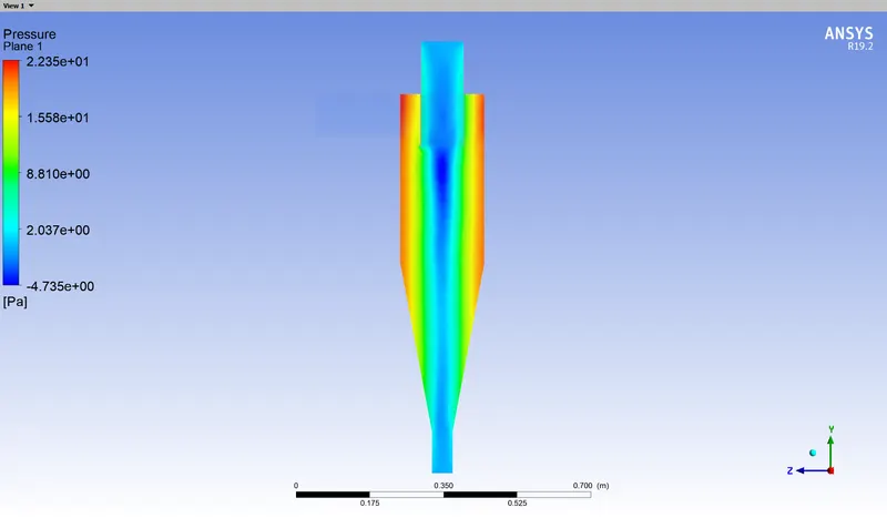 |
| Case III | 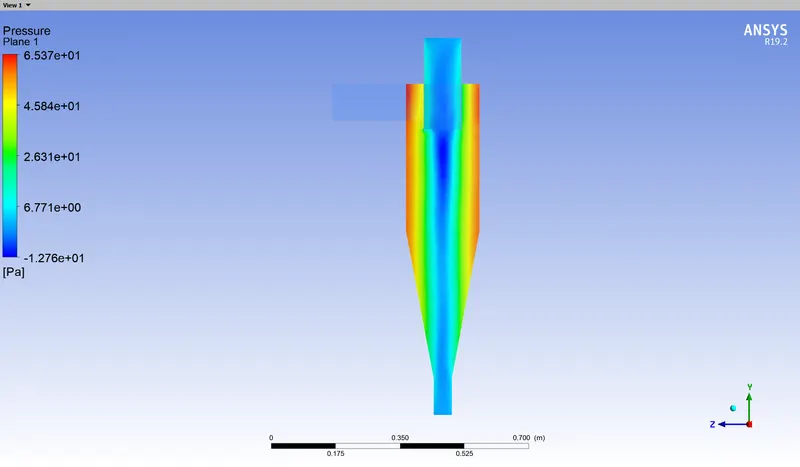 |
Pressure drop values obtained from the console:
| Case I | 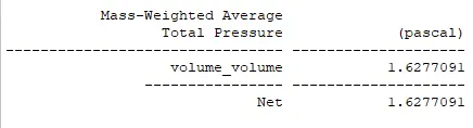 |
| Case II | 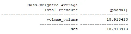 |
| Case III | 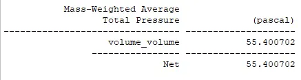 |
Console display values:
| Case I |  |
| Case II |  |
| Case III |  |
Upon observing the pressure contours and the pressure drop values above, a couple of inferences can be made.
The inlet velocity of the particles and the gas itself, has a profound effect on the pressure drop in the system. This rotation of the fluid inside the cyclone separator decreases the pressure at the center of the cylinder. The lower the pressure along the axis of the separator, the more centripetal force it will exert on the gas-stream entering it. Increasing the inlet velocity increases the pressure drop in the system, and this is shown in the console display results of each case.
The pressure drop seen in case I is low, and observing this, it can be said that it may not exert enough centripetal force to separate the gas from the particles. The other issue with the low inlet velocity is the fact that the particles within the gas stream do not possess enough momentum to exit through the bottom outlet. This issue is exacerbated by the fact that the conical section of the separator exerts a force normal to the inclined surface. Similar to a point mentioned above, the momentum possessed by the particle is enough to counteract the centripetal force and the force applied by the inclined wall, but not enough to exceed these forces and continue along its path. The particle ends up in limbo, and remains in the separator.
The problems stated above do not occur in Case II and Case III. In fact, the value of pressure drop in case III is so high that all of the particles get trapped in the bottom outlet, and the separation efficiency reaches cent percent. This is the ideal case, as the pressure drop is enough to separate the gas from the particles, and the particles have enough momentum to reach the bottom outlet, and are eventually trapped. The console display values reenforce this point, and is visually proven in the plots displayed below.
| Case | Particle tracking(velocity) |
| Case I | 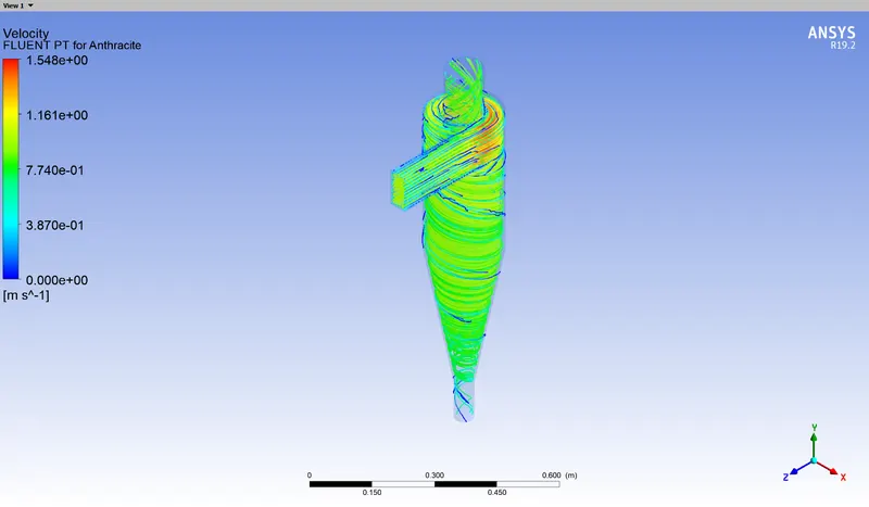 |
| Case II | |
| Case III | 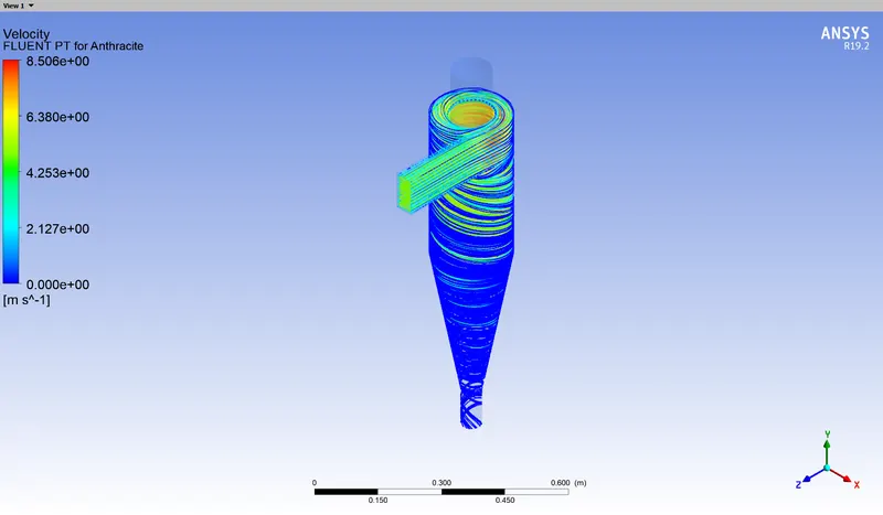 |
The number of particles near the boundary of Case I are extremely low, and only a couple of particles are trapped. This is in stark contrast to Case III, in which all of the particles have been successfully collected.
Separation Efficiency:
`text(D) = 5 mum, text(v) = 1 m/s`:
`eta_(text(separation)) = 4/(142 - 112) = 0.1334`
`text(D) = 5 mum, text(v) = 3 m/s`:
`eta_(text(separation)) =136/(142 - 0) = 0.9577`
`text(D) = 5 mum, text(v) = 5 m/s`
`eta_(text(separation)) =142/(142 - 0) = 1`
After computing the separation efficiency, it can be stated that the velocity particles plays a vital role in gas separation in a cyclone separator, and the particle diameter is not the sole factor upon which particle separation is dependent on.
Conclusions:
Analyzing the results, it can be concluded that the separation efficiency of a cyclone separator depends heavily on the size of the particle that the gas carries. If the particle size is below a certain value, the cyclone separator will not be able to successfully separate the gas from the particles. It can also be stated that this should be a design consideration for a cyclone separator. The diameter of the separator itself may have an effect on the particle separation, as the force exerted by the low pressure zone depends on the radial distance from the axis. Adjusting this during the design of a cyclone separator may yield more favourable results.
The particle velocity directly influences the strength of the centripetal forces acting on the gas, as the pressure of the low pressure zone along the axis decreases with an increase in velocity. If the velocity of the gas-stream is not adequate, particles will not be separated from the gas, irrespective of the particle size. Hence, the inlet velocity is also a design consideration for a cyclone separator.