Cyclone Separator Challenge
SIMULATION ON A CYCLONE SEPERATOR:
AIM:
To perform numerical simulation on cyclone separator and calculate the separation efficiency and pressure drop.
OBJECTIVES:
- To understand about any four empirical models used to calculate the cyclone separator efficiency.
- To perform an analysis on a given cyclone separator model by varying the particle diameter from 1 μm to 10 μm and calculate the separation efficiency in each case and to discuss the results. with velocity of 3m/s in both cases
- To perform an analysis on a given cyclone separator model by varying the particle velocity from 1 m/sec to 5 m/sec and calculate the separation efficiency and pressure drop in each case. Discuss the results. [Use particle diameter size as 5 μm]
DESCRIPTION:
Cyclone Seperator:
Cyclone Separator is a device which is used to separate the particulate matter from emissions without using the filter. Rotational effects and gravity are used to separate mixtures of solids and fluids.
Air flows in a helical pattern, beginning at the top (wide end) of the cyclone and ending at the bottom (narrow) end before exiting the cyclone in a straight stream through the centre of the cyclone and out the top. Larger (denser) particles in the rotating stream have too much inertia to follow the tight curve of the stream, and thus strike the outside wall, then fall to the bottom of the cyclone where they can be removed.
Few of the emperical models that are used to calculate the cyclone seperator efficiency are as follows:
1.Iozia and Leith Model
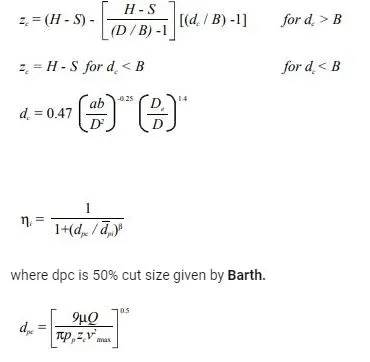
This includes particle bounce or re-entrainment and turbulent diffusion at the cyclone wall.
Li and Wang's model was developed based on the following assumptions:
- The radial particle velocity and the radial concentration profile are not constant, for uncollected particles within the cyclones.
- Boundary conditions with the consideration of turbulent diffusion coefficient and particle bounce re-entrainment on the cyclone wall are:
The Tangential velocity is related to the cyclone by, UR^n = constant
The concentration distribution in a cyclone is given as:
The resultant expression of the collection efficiency for particle
of my size is given as
3. Koch and Licht Model :
This Model recognizes the inherently turbulent nature of cyclones and the distribution of gas residence times within the cyclone.
It describes particle motion in the entry and the collection regions with some assumptions,
- The tangential velocity of particles is equal to the tangential velocity of the gas flow i.e. 'no slip' in tangential direction between the particle and the gas.
- The tangential velocity is related to the radius of the cyclone by UR^n = constant
A force balance and the equation on this particles collection yield the grade efficiency,
where G,
G is a factor related to the configuration of the cyclone, n is
related to the vortex and τ is the relaxation term.
4. Lapple Model :
- It is a 1951 model developed by LAPPLE assuming that a particle entering a cyclone is evenly distributed along with the inlet opening.
- It is based on Force Balance without considering the flow resistance.
In this model, the particle that travels from inlet half-width to the wall in the Cyclone is collected with 50% efficiency.
Efficiency,
Nc = No. of revolutions
NUMERICAL SIMULATION:
1. GEOMETRY :
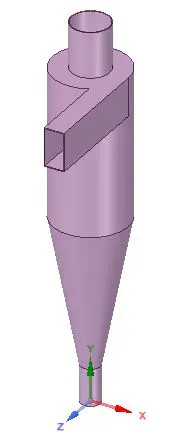
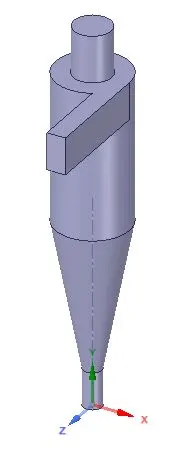
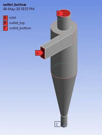
- The 3D model of the cyclone seperator has been shown above.Since this is not a conjugate heat transfer problem where the solid-fluid interaction is to be taken into account.We are only interested in the fluid volume of the above geometry , which is provided below:
2.MESHING:
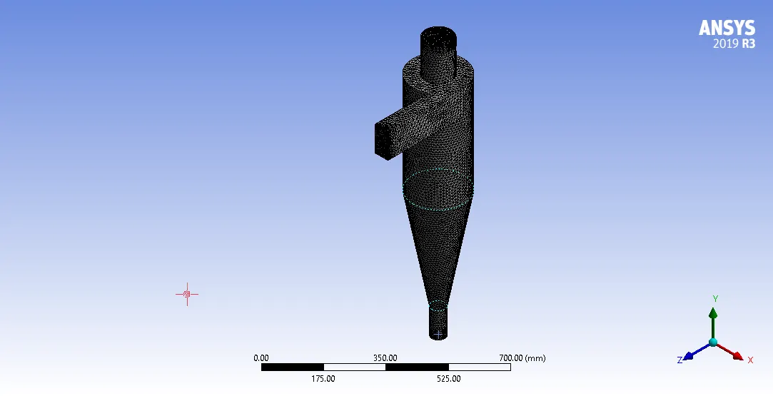
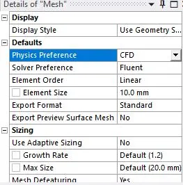
- Element Type : Tetrahedral
The mesh metrics for the element quality , orthogonal quality and skewness has been shown below:
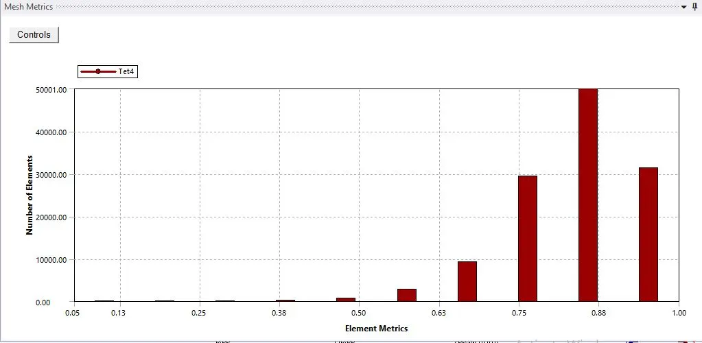
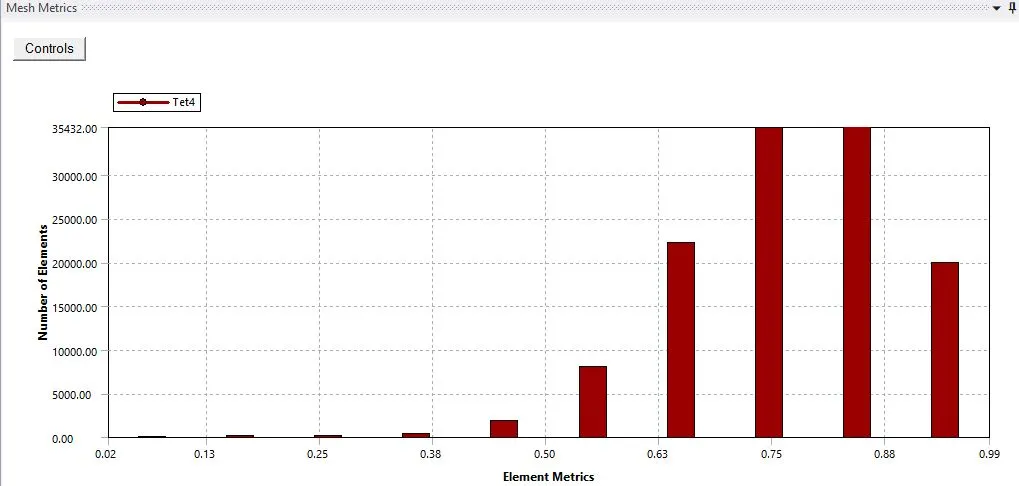
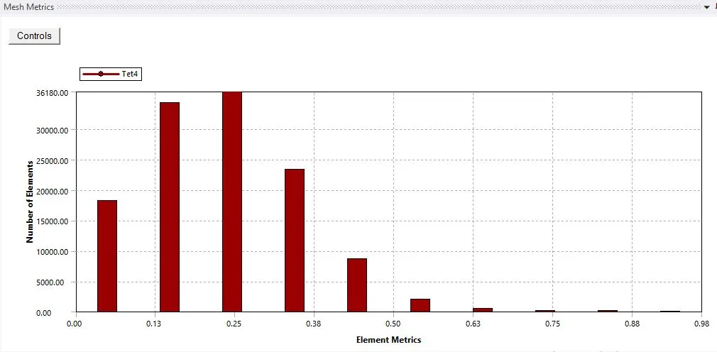
- From the above mesh metric graphs , we can conclude that the meshing done for the geometry is better , as the average orthogonal qaulity of the elements are 0.76 and skewness is less than 0.8.
3. SETUP :
Solver :
- Type : Pressure-Based
- Time : Steady
- Velocity Formulation : Absolute
Gravity :
- -9.81 `m/s^2`
Model :
- Multiphase : OFF
- Viscous :
- RNG k - epsilon
- Swirl Dominant Flow
Discrete Phase Model (DPM) :
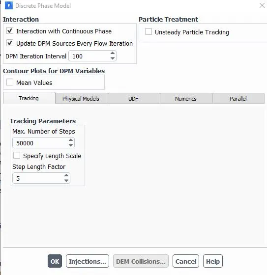
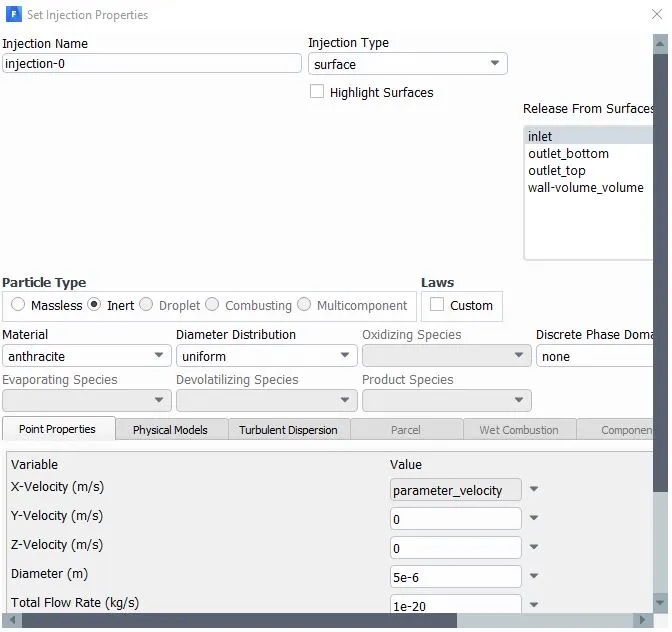
Particle Diameter : PART 1 - 1 `mum`to 10 `mum`
PART 2 - 5 `mum`
Particle Velocity ( X- direction ) : PART 1 : 3 m/s
PART 2 : 1 to 5 m/s
Boundary Conditions:
- Inlet : Velocity Inlet ( PART 1: 3 m/s
PART 2 : 1 to 5 m/s )
Reflect
- Wall : Reflect
- Outlet (Top) : Pressure Outlet
Escape
- Outlet (Bottom) : Pressure Outlet
Trap
Calculation :
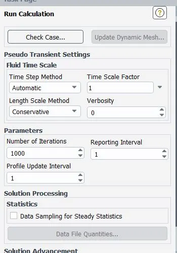
4.SOLUTION & RESULTS :
PART 1:
Simulation was carried out by varying the paritlce diameter from 1 `mum` to 10 `mum` and the results were studied regarding the cyclone collector efficiency as discussed below:
Particle Diameter- 1 `mum` :

Particle Diameter- 2 `mum`:

Particle Diameter- 3 `mum`:

Particle Diameter- 4 `mum`:

Particle Diameter- 5 `mum`:

Particle Diameter- 6 `mum`:

Particle Diameter- 7 `mum`:

Particle Diameter- 8 `mum`:

Particle Diameter- 9 `mum`:

Particle Diameter- 10 `mum`:

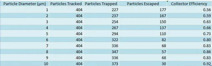
Collector efficiency is calculated as , `eta`= (Number of Particles Trapped) / (Number of Particles Tracked)
- The variation of cyclone seperator efficiency with the diameter of the particle being tracked is provided below:
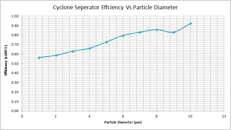
- From the above graph, we are able to conclude that the efficiency of a cyclone seperator increases with particle diameter of the particle which is being tracked.Further,the highest efficiency for the cyclone seperator is found to be for a particle diameter of 10 `mum` with a cyclone seperator efficiency of 92 %.
PART II
Particle Velocity = 5 m/s
1.Residual Plot:
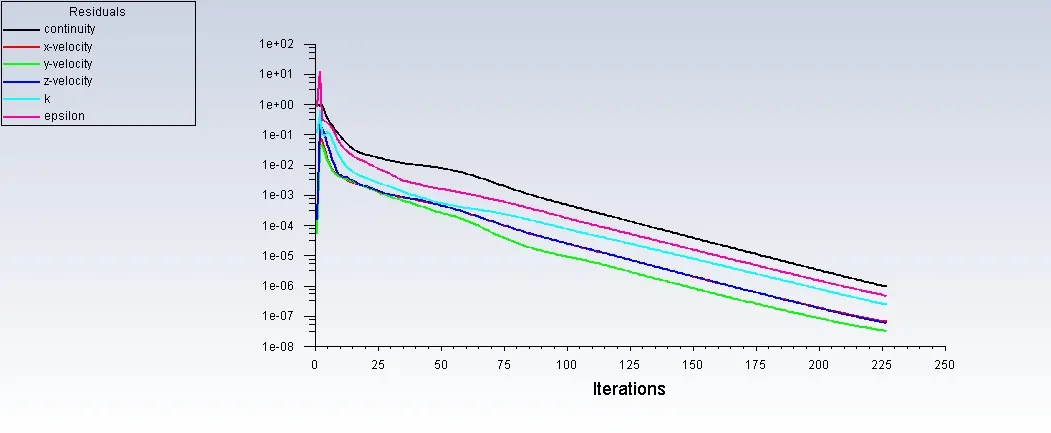
- The flow converged at about 230 iterations.
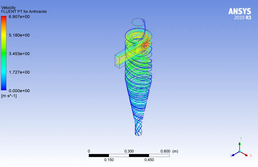
2. Velocity Contour Plot:
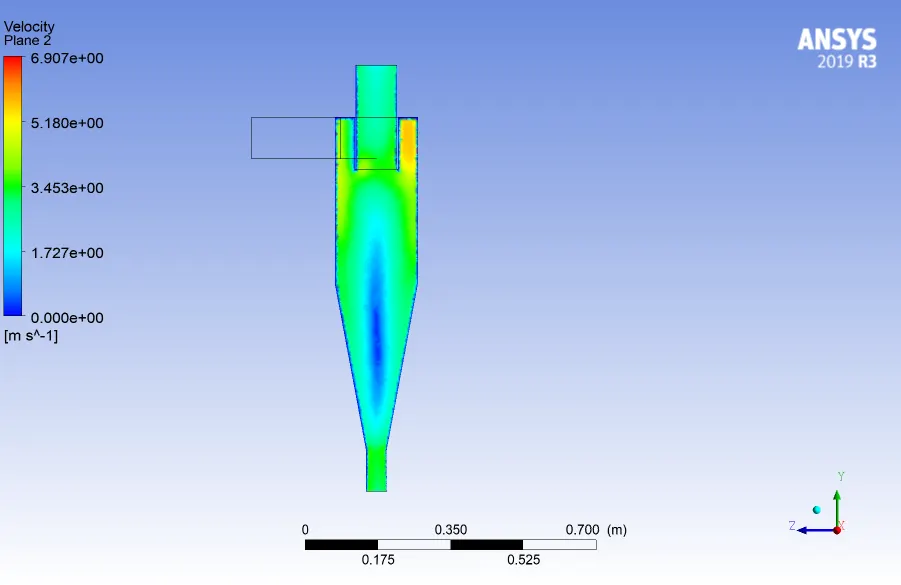
3.Pressure Contour Plot:
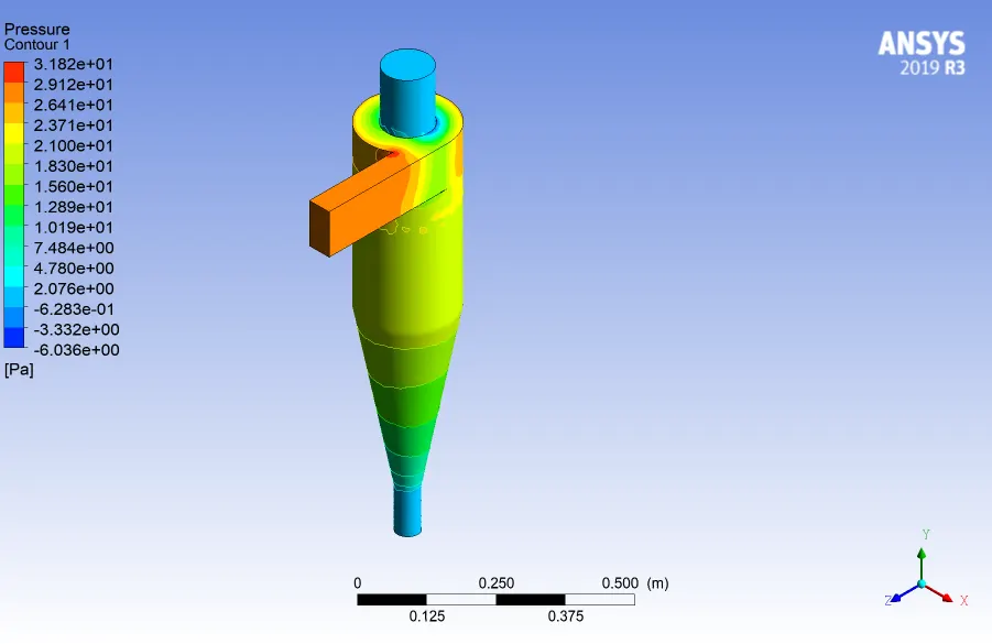
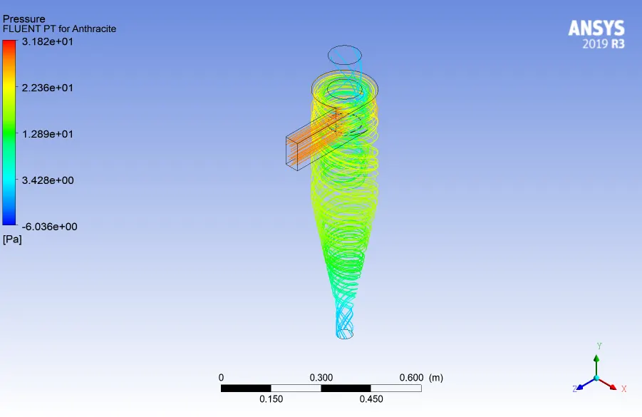
4. Particle Track Contour:
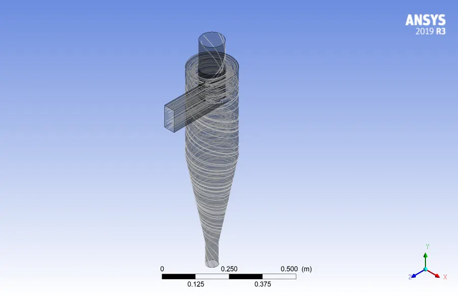

- The above figure shows the number of particle tracked,trapped and escaped for a particle velocity of 5 m/s.
Particle Velocity = 4 m/s :
1.Residual Plot:

- The flow converged at an iteration of 224
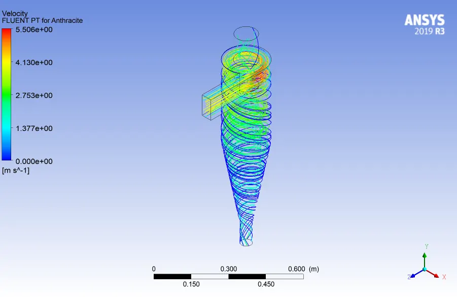
2.Velocity Contour:
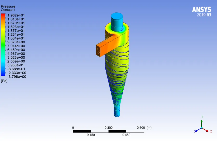
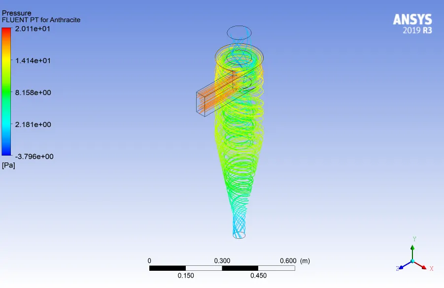
3.Pressure Contour:
4.Particle Track Plot:
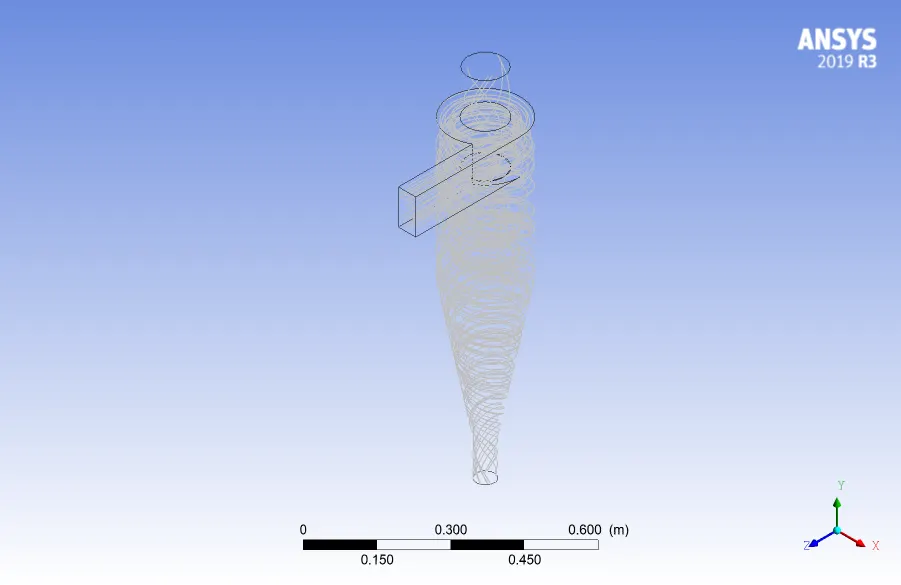

- The above figure shows the number of particles that were trapped and escaped for an inlet velocity of 4 m/s.
Particle Velocity = 3 m/s
1.Residual Plot:
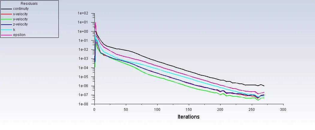
- The flow converged about an iteration of 270.
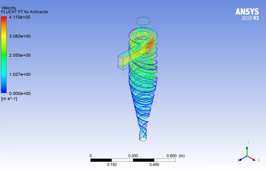
2.Velocity Plot:
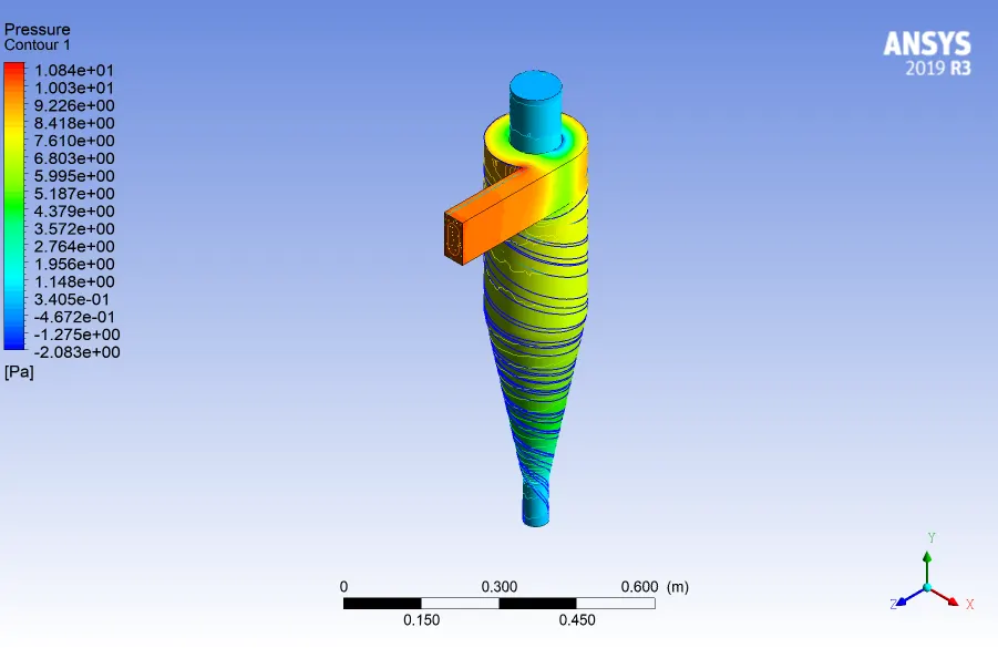
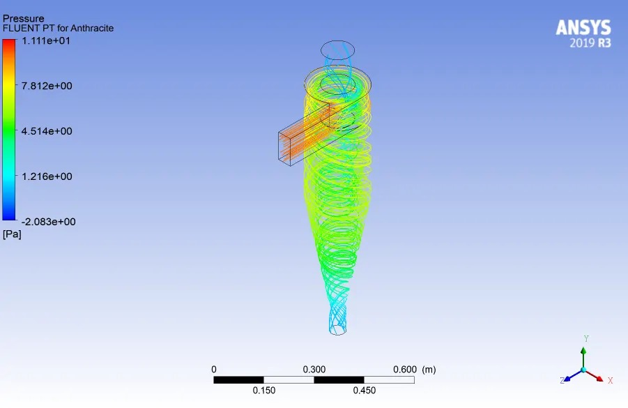
3.Pressure Plot:
4.Particle Track:
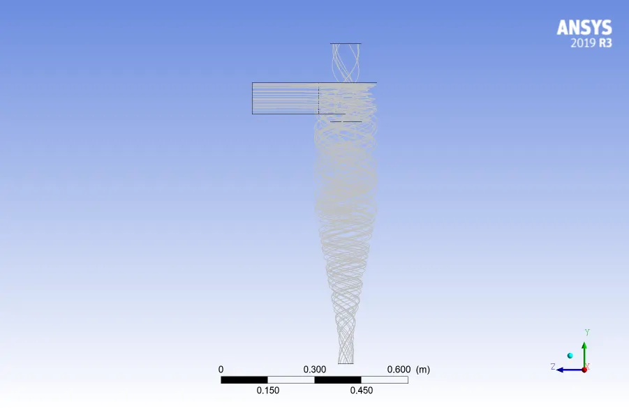

Particle Velocity = 2 m/s
1.Residual Plot:
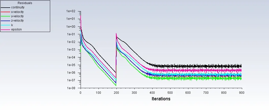
2.Velocity Plot:
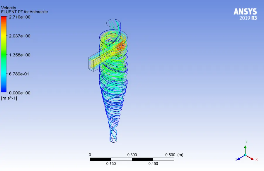
3.Pressure Plot:
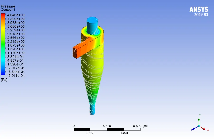
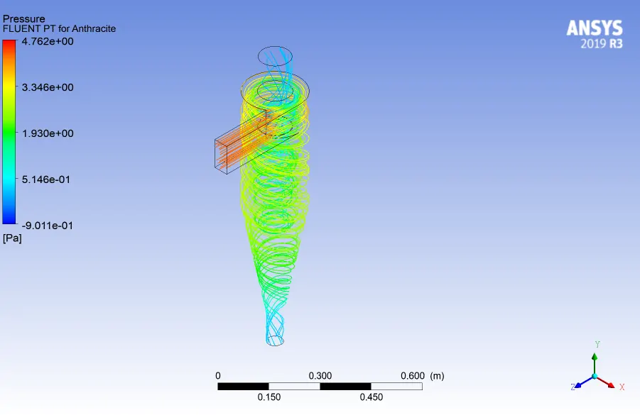
4.Particle Track:
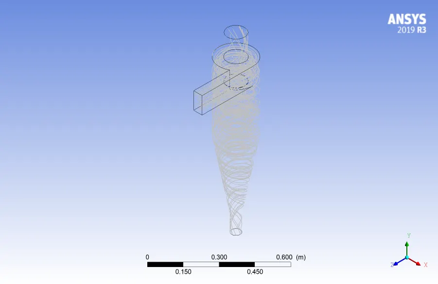

The pressure drop and the cyclone seperator efficiency for each case has been obtained and is tabulated as below:
| Particle Velocity (m/s) | Pressure Drop (Pa) | Particle_Tracked | Particle_Trapped | Particle_Escaped | Cyclone Seperator Efficiency | ||||
| 1 |
|
|
|
|
0.505 | ||||
| 2 |
|
|
|
|
0.683 | ||||
| 3 |
|
|
|
|
0.733 | ||||
| 4 |
|
|
|
|
0.782 | ||||
| 5 |
|
|
|
|
0.824 |
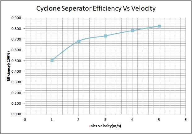
- The above plot shows the variation of cyclone seperator efficiency with the particle injection velocity.It is clearly evident from the plot that the with an increase in the injection velocity of the particle , in this case anthracite , the cyclone seperator efficiency increases.
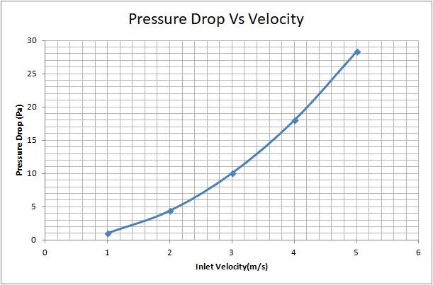
- The above plot shows the variation of the pressure drop with that of the inlet injection velocity of the particle.The pressure increases with an increase in the particle velocity.
CONCLUSION:
The numerical simulation on the cyclone seperator has been carried out in two different cases
- Varying the particle diameter by keeping a constant particle velocity of 3 m/s.
- Varying the velocity of the particle by keeping the diameter of particle constant with a value of 5`mum`.
And the following observations can be concluded from the analysis carried out:
- The cyclone seperator efficiency depends on the particle diameter & injection velocity of the particle
- For a larger particle diameter , it can be observed that cyclone seperator efficiency of about 92 % can be achieved.But the performance of the cyclone seperator is not appreciable for a lower diameter solid particles.
- Further it can be observed that there is a tradeoff between the cyclone seperator efficiency and pressure drop.It can be noted that, with an increase in the injection velocity of the particle ,there is an increase in the cyclone seperator efficiency and also , there is an increase in the pressure drop in the cyclone seperator.
- The tradeoff between the pressure drop and the efficiency could be overcomed by modifying the geometry of the cyclone seperator ,which could be analysed in further analysis.
ThankYou