Creation of Multiple viewports, Scaling the drawing and setting in Template in AutoCad
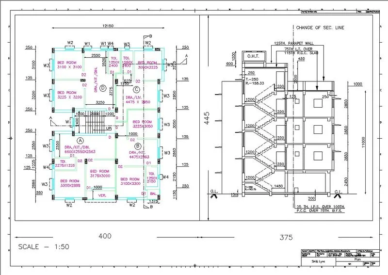
1.Create a layout of the Plan and Section A of the project in Challenges 7, using the template Tutorial-mArch.dwt in a scale as given in the Figure. Use the MV command to create the viewport of the size as shown in Figure. Also, use the ATTEDIT command to edit the information in the title block. Use A1 size for the layout. Take a plot
Aim: To create the layout of the plan and section A of the project in challenge 7 as shown in the figure above in AutoCAD
Introduction: The layout is created in Auto CAD by using the template Tutorial-mArch.dwt in a scale as given in the figure. The procedure is explained in detail with diagrams of each step and the final result is given.
Procedure:
step-1: Open AutoCAD
step-2: Open challenge 7 file
step-3: Go to Layout
step-4: Enter "Layout" to create a new layout tab
step-5: Enter the "MV" command
step-6: Select "Template"
step-7: Open a new dialogue box
step-8: Select Tutorial-mArch template
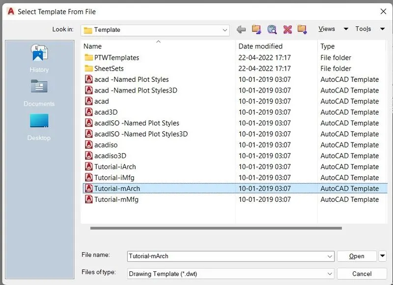
step-9: Enter "Pagesetup" in the command line
step-10: Select Layout and click modify
step-11: Select ISO A1
step-12: Select OK
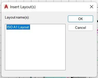
step-13: Go to the Layout tab
step-14: Enter the "REC" command
step-15: Plot Rectangle in paper space
step-16: Rectangle size 400 X 445
step-17: Another Rectangle with a dimension of 375 X 445
step-18: Enter "MV"
step-19: Select "Object"
step-20: Select the Rectangle object we drawn
step-21: Then we have a drawing from a model
step-22: Enter "MS" model space
step-23: Select 1:50 scale
step-24: Enter the "PAN" command to pan the drawing and fit it into the model space
step-25: Go to another model space
step-26: Select 1:50 scale
step-27: Pan section - A from a model
step-28: Enter "PS"
step-29: Enter "DIMLIN" to mention the linear dimension of the rectangle
step-30: Enter "DT" to annotate the scale
step-31: Enter "ATTEDIT" in the command line
step-32: Edit the Attributes in the paper space
step-33: Click OK
step-33: Go to the Print option
step-34: Select required properties and go to preview
step-35: Take a Screenshot and attach it here.
Result:
We create the layout as per shown in figure by using AutoCAD.
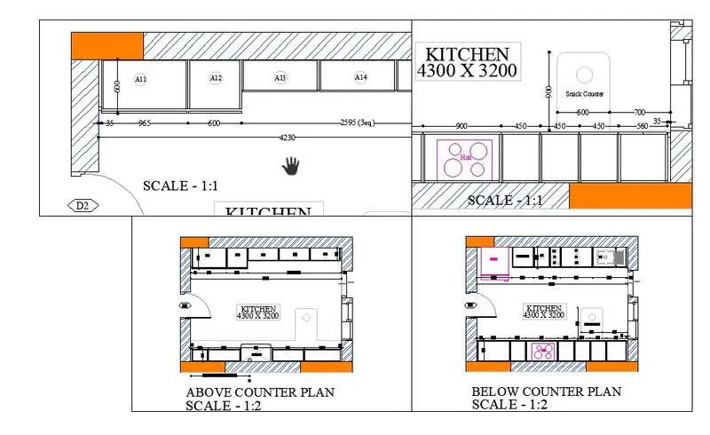
2. Create a layout of the Kitchen drawn in Challenge 9 as shown in Figure. Use the scale as shown in the Figure. Use an A4 Size page for the layout. Take a plot.
Aim: To create the layout of the kitchen of the project in challenge 9 as shown in the figure above in AutoCAD
Introduction: The layout is created in Auto CAD by using the scale given in the figure. The procedure is explained in detail with diagrams of each step and the final result is given.
Procedure:
step-1: Open AutoCAD
step-2: Open challenge 9 file
step-3: Go to Layout
step-4: Enter "Layout" to create a new layout tab
step-5: Enter "Pagesetup" in the command line
step-6: Select Layout and click modify
step-7: Select A4
step-8: Click OK
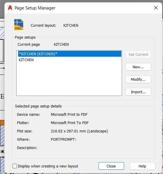
step-9: Enter "REC" command to create a rectangle to plot the model into paper space
step-10: Enter Four rectangle
step-11: Click OK
step-12: Enter "MV"
step-13: Select "Object"
step-14: Select all the objects in the Paper space
step-15: Now we have drawing in layout
step-16: Enter "MS"
step-17: Select 1:2 scale
step-18: Pan the kitchen drawing
step-19: Plot the drawing as shown in figure
step-20: Click another model space
step-21: Select 1:2 scale
step-22: Pan the kitchen drawing
step-23: Plot the drawing as shown in figure
step-24: Click another model space
step-25: Select 1:1 scale
step-26: Pan the kitchen drawing
step-27: Plot the drawing as shown in figure
step-28: Click another model space
step-29: Select 1:1 scale
step-30: Pan the kitchen drawing
step-31: Plot the drawing as shown in the figure
step-32: Enter "DT" to annotate the scale
step-33: Go to the Print option
step-34: Select required properties and go to preview
step-35: Take a Screenshot and attach it here.
Result:
We create the layout as per shown in the figure by using AutoCAD.
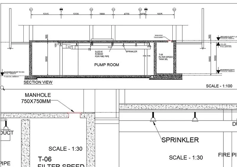
3.Create a layout of the section created in Challenges 9. Use the scale as mentioned in the Figure. Use the MV command to create multiple viewports. Take a plot.
Aim: To create the layout of the kitchen of the project in challenge 9 as shown in the figure above in AutoCAD
Introduction: The layout is created in Auto CAD by using the scale given in the figure. The procedure is explained in detail with diagrams of each step and the final result is given.
Procedure:
step-1: Open AutoCAD
step-2: Open challenge 9 file
step-3: Go to Layout
step-4: Enter "Layout" to create a new layout tab
step-5: Click OK
step-6: Enter "REC" command to create a rectangle to plot the model into paper space
step-7: Enter three rectangle
step-8: Click OK
step-9: Enter "MV"
step-10: Select "Object"
step-11: Select all the objects in the Paper space
step-12: Now we have the drawing in layout
step-13: Enter "MS"
step-14: Select 1:100 scale
step-15: Pan the kitchen drawing
step-16: Plot the drawing as shown in figure
step-17: Click another model space
step-18: Select 1:30 scale
step-19: Pan the kitchen drawing
step-20: Plot the drawing as shown in the figure
step-21: Click another model space
step-22: Select 1:30 scale
step-23: Pan the kitchen drawing
step-24: Plot the drawing as shown in the figure
step-25: Enter "DT" to annotate the scale
step-26: Go to the Print option
step-27: Select required properties and go to preview
step-28: Take a Screenshot and attach it here.
Result:
We create the layout as per shown in the figure by using AutoCAD.