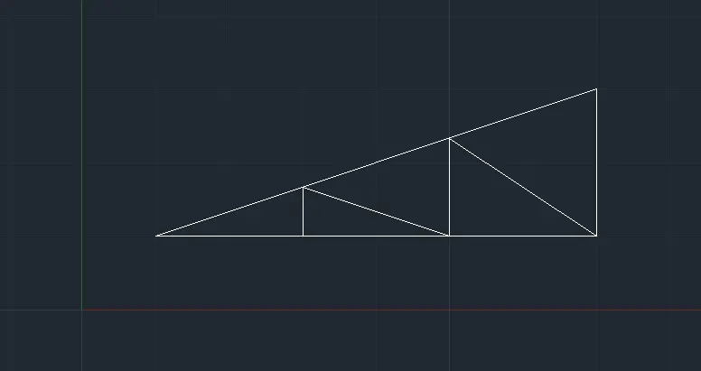
Creation of geometries by Coordinate system methods using AutoCad
1)
AIM: To create the below geometry using all the coordinate system methods and by using the line tool.
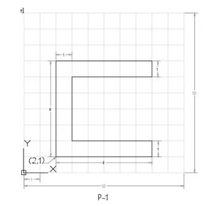
PROCEDURE:
- Create a new sheet in AutoCAD and set the required format for units of measure.
- Drawing this geometry by using the Absolute coordinates method.
- Select the line L tool from commands, toolbar, or draw menu.
- Give the reference point as (x,y) in the x and y-direction from the origin (0,0). The first point of the diagram is (2,1).
- The next point is (8,1).
- The next point is (8,2).
- The next point is (3,2).
- The next point is (3,6).
- The next point is (8,6).
- The next point is (8,7).
- The next point is (2,7).
- Finally use the close command by typing C in the command line and enter.
RESULT:
The diagram of the given plan is drawn by using the absolute coordinate system as per dimensions using the AutoCAD software.
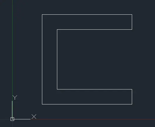
PROCEDURE:
- Create a new sheet in AutoCAD and set the required format for units of measure.
- Drawing this geometry by using the relative rectangle coordinates method.
- Select the line L tool from commands, toolbar, or draw menu.
- Give the reference point as (x,y) in the x and y-direction from the origin (0,0). The first point of the diagram is (2,1).
- The next point is (@6,0).
- The next point is (@0,1).
- The next point is (@-5,0).
- The next point is (@0,4).
- The next point is (@5,0).
- The next point is (@0,1).
- The next point is (@-6,0).
- Finally use the close command by typing C in the command line and enter.
RESULT:
The diagram of the given plan is drawn by using the relative rectangle coordinate system as per dimensions, using the AutoCAD software.
PROCEDURE:
- Create a new sheet in AutoCAD and set the required format for units of measure.
- Drawing this geometry by using the relative polar coordinates method.
- Select the line L tool from commands, toolbar, or draw menu.
- Give the reference point as (x,y) in the x and y-direction from the origin (0,0). The first point of the diagram is (2,1).
- The next point is (@6<0°).
- The next point is (@1<90°).
- The next point is (@5<180°).
- The next point is (@4<90°).
- The next point is (@5<0°).
- The next point is (@1<90°).
- The next point is (@6<180°).
- Finally use the close command by typing C in the command line and enter.
RESULT:
The diagram of the given plan is drawn by using the relative polar coordinate system as per dimensions, using the AutoCAD software.
PROCEDURE:
- Create a new sheet in AutoCAD and set the required format for units of measure.
- Drawing this geometry by using the Direct distance entry method.
- Select the line L tool from commands, toolbar, or draw menu.
- Give the reference point as (x,y) in the x and y-direction from the origin (0,0). The first point of the diagram is (2,1).
- The next point: Position the cursor in the needed direction and then enter the distance 6.
- The next point: Position the cursor in the needed direction and then enter the distance 1.
- The next point: Position the cursor in the needed direction and then enter the distance 5.
- The next point: Position the cursor in the needed direction and then enter the distance 4.
- The next point: Position the cursor in the needed direction and then enter the distance 5.
- The next point: Position the cursor in the needed direction and then enter the distance 1.
- The next point: Position the cursor in the needed direction and then enter the distance 6.
- Finally use the close command by typing C in the command line and enter.
RESULT:
The diagram of the given plan is drawn by using the Direct distance entry method as per dimensions, using the AutoCAD software.
2)
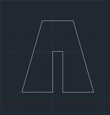
AIM: To create the below geometry using all the coordinate system methods and by using the line tool.
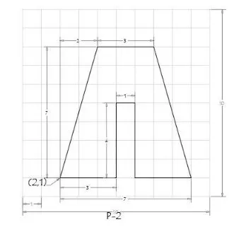
PROCEDURE:
- Create a new sheet in AutoCAD and set the required format for units of measure.
- Drawing this geometry by using the Absolute coordinates method.
- Select the line L tool from commands, toolbar, or draw menu.
- Give the reference point as (x,y) in the x and y-direction from the origin (0,0). The first point of the diagram is (2,1).
- The next point is (5,1).
- The next point is (5,5).
- The next point is (6,5).
- The next point is (6,1).
- The next point is (9,1).
- The next point is (7,8).
- The next point is (4,8).
- Finally use the close command by typing C in the command line and enter.
RESULT:
The diagram of the given plan is drawn by using the absolute coordinate system as per dimensions using the AutoCAD software.
PROCEDURE:
- Create a new sheet in AutoCAD and set the required format for units of measure.
- Drawing this geometry by using the relative rectangle coordinates method.
- Select the line L tool from commands, toolbar, or draw menu.
- Give the reference point as (x,y) in the x and y-direction from the origin (0,0). The first point of the diagram is (2,1).
- The next point is (@3,0).
- The next point is (@0,4).
- The next point is (@1,0).
- The next point is (@0,-4).
- The next point is (@3,0).
- The next point is (@-2,7).
- The next point is (@-3,0).
- Finally use the close command by typing C in the command line and enter.
RESULT:
The diagram of the given plan is drawn by using the relative rectangle coordinate system as per dimensions, using the AutoCAD software.
PROCEDURE:
- Create a new sheet in AutoCAD and set the required format for units of measure.
- Drawing this geometry by using the relative polar coordinates method.
- Select the line L tool from commands, toolbar, or draw menu.
- Give the reference point as (x,y) in the x and y-direction from the origin (0,0). The first point of the diagram is (2,1).
- The next point is (@3<0°).
- The next point is (@4<90°).
- The next point is (@1<0°).
- The next point is (@4<270°).
- The next point is (@3<0°).
- The next point is (@7.28010989<105.945396°).
- The next point is (@3<180°).
- Finally use the close command by typing C in the command line and enter.
RESULT:
The diagram of the given plan is drawn by using the relative polar coordinate system as per dimensions, using the AutoCAD software.
PROCEDURE:
- Create a new sheet in AutoCAD and set the required format for units of measure.
- Drawing this geometry by using the Direct distance entry method.
- Select the line L tool from commands, toolbar, or draw menu.
- Give the reference point as (x,y) in the x and y-direction from the origin (0,0). The first point of the diagram is (2,1).
- The next point: Position the cursor in the needed direction and then enter the distance 3.
- The next point: Position the cursor in the needed direction and then enter the distance 4.
- The next point: Position the cursor in the needed direction and then enter the distance 1.
- The next point: Position the cursor in the needed direction and then enter the distance 4.
- The next point: Position the cursor in the needed direction and then enter the distance 3.
- The next point: Position the cursor in the needed direction and then enter the distance 7.28010989.
- The next point: Position the cursor in the needed direction and then enter the distance 3.
- Finally use the close command by typing C in the command line and enter.
RESULT:
The diagram of the given plan is drawn by using the Direct distance entry method as per dimensions, using the AutoCAD software.
3)
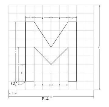
AIM: To create the below geometry using all the coordinate system methods and by using the line tool.
PROCEDURE:
- Create a new sheet in AutoCAD and set the required format for units of measure.
- Drawing this geometry by using the Absolute coordinates method.
- Select the line L tool from commands, toolbar, or draw menu.
- Give the reference point as (x,y) in the x and y-direction from the origin (0,0). The first point of the diagram is (2,1).
- The next point is (3,1).
- The next point is (3,5).
- The next point is (5,3).
- The next point is (7,5).
- The next point is (7,1).
- The next point is (8,1).
- The next point is (7,8).
- The next point is (5,5).
- The next point is (3,8).
- The next point is (2,8).
- Finally use the close command by typing C in the command line and enter.
RESULT:
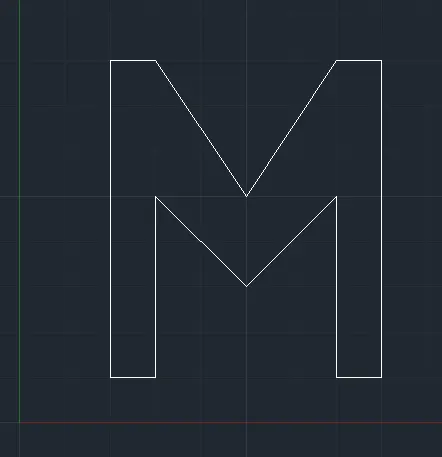
The diagram of the given plan is drawn by using the absolute coordinate system as per dimensions using the AutoCAD software.
PROCEDURE:
- Create a new sheet in AutoCAD and set the required format for units of measure.
- Drawing this geometry by using the relative rectangle coordinates method.
- Select the line L tool from commands, toolbar, or draw menu.
- Give the reference point as (x,y) in the x and y-direction from the origin (0,0). The first point of the diagram is (2,1).
- The next point is (@0,1).
- The next point is (@0,4).
- The next point is (@2,-2).
- The next point is (@2,2).
- The next point is (@0,-4).
- The next point is (@1,0).
- The next point is (@0,7).
- The next point is (@-1,0).
- The next point is (@-2,-3).
- The next point is (@-1,0).
- Finally use the close command by typing C in the command line and enter.
RESULT:
The diagram of the given plan is drawn by using the relative rectangle coordinate system as per dimensions, using the AutoCAD software.
PROCEDURE:
- Create a new sheet in AutoCAD and set the required format for units of measure.
- Drawing this geometry by using the relative polar coordinates method.
- Select the line L tool from commands, toolbar, or draw menu.
- Give the reference point as (x,y) in the x and y-direction from the origin (0,0). The first point of the diagram is (2,1).
- The next point is (@1<0°).
- The next point is (@4<90°).
- The next point is (@2.8422712<315°).
- The next point is (@2.8422712<45°).
- The next point is (@4<270°).
- The next point is (@1<0°).
- The next point is (@7<90°).
- The next point is (@1<180°).
- The next point is (@3.6055128<236.309933°).
- The next point is (@3.6055128<123.690068°).
- The next point is (@1<180°).
- Finally use the close command by typing C in the command line and enter.
RESULT:
The diagram of the given plan is drawn by using the relative polar coordinate system as per dimensions, using the AutoCAD software.
PROCEDURE:
- Create a new sheet in AutoCAD and set the required format for units of measure.
- Drawing this geometry by using the Direct distance entry method.
- Select the line L tool from commands, toolbar, or draw menu.
- Give the reference point as (x,y) in the x and y-direction from the origin (0,0). The first point of the diagram is (2,1).
- The next point: Position the cursor in the needed direction and then enter the distance 1.
- The next point: Position the cursor in the needed direction and then enter the distance 4.
- The next point: Position the cursor in the needed direction and then enter the distance 2.82842712.
- The next point: Position the cursor in the needed direction and then enter the distance 2.82842712.
- The next point: Position the cursor in the needed direction and then enter the distance 4.
- The next point: Position the cursor in the needed direction and then enter the distance 1.
- The next point: Position the cursor in the needed direction and then enter the distance 7.
- The next point: Position the cursor in the needed direction and then enter the distance 1.
- The next point: Position the cursor in the needed direction and then enter the distance 3.6055128.
- The next point: Position the cursor in the needed direction and then enter the distance 3.6055128.
- The next point: Position the cursor in the needed direction and then enter the distance 1.
- Finally use the close command by typing C in the command line and enter.
RESULT:
The diagram of the given plan is drawn by using the Direct distance entry method as per dimensions, using the AutoCAD software.
4)
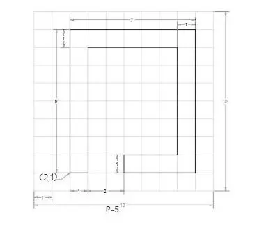
AIM: To create the below geometry using all the coordinate system methods and by using the line tool.
PROCEDURE:
- Create a new sheet in AutoCAD and set the required format for units of measure.
- Drawing this geometry by using the Absolute coordinates method.
- Select the line L tool from commands, toolbar, or draw menu.
- Give the reference point as (x,y) in the x and y-direction from the origin (0,0). The first point of the diagram is (2,1).
- The next point is (3,1).
- The next point is (3,8).
- The next point is (8,8).
- The next point is (8,2).
- The next point is (5,2).
- The next point is (5,1).
- The next point is (9,1).
- The next point is (9,9).
- The next point is (2,9).
- Finally use the close command by typing C in the command line and enter.
RESULT:
The diagram of the given plan is drawn by using the absolute coordinate system as per dimensions using the AutoCAD software.
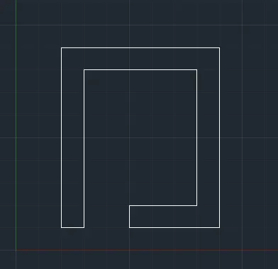
PROCEDURE:
- Create a new sheet in AutoCAD and set the required format for units of measure.
- Drawing this geometry by using the relative rectangle coordinates method.
- Select the line L tool from commands, toolbar, or draw menu.
- Give the reference point as (x,y) in the x and y-direction from the origin (0,0). The first point of the diagram is (2,1).
- The next point is (@1,0).
- The next point is (@0,7).
- The next point is (@5,0).
- The next point is (@0,-6).
- The next point is (@-3,0).
- The next point is (@0,-1).
- The next point is (@4,0).
- The next point is (@0,8).
- The next point is (@-7,0).
- Finally use the close command by typing C in the command line and enter.
RESULT:
The diagram of the given plan is drawn by using the relative rectangle coordinate system as per dimensions, using the AutoCAD software.
PROCEDURE:
- Create a new sheet in AutoCAD and set the required format for units of measure.
- Drawing this geometry by using the relative polar coordinates method.
- Select the line L tool from commands, toolbar, or draw menu.
- Give the reference point as (x,y) in the x and y-direction from the origin (0,0). The first point of the diagram is (2,1).
- The next point is (@1<0°).
- The next point is (@7<90°).
- The next point is (@5<0°).
- The next point is (@6<270°).
- The next point is (@3<180°).
- The next point is (@1<270°).
- The next point is (@4<0°).
- The next point is (@8<90°).
- The next point is (@7<180°).
- Finally use the close command by typing C in the command line and enter.
RESULT:
The diagram of the given plan is drawn by using the relative polar coordinate system as per dimensions, using the AutoCAD software.
PROCEDURE:
- Create a new sheet in AutoCAD and set the required format for units of measure.
- Drawing this geometry by using the Direct distance entry method.
- Select the line L tool from commands, toolbar, or draw menu.
- Give the reference point as (x,y) in the x and y-direction from the origin (0,0). The first point of the diagram is (2,1).
- The next point: Position the cursor in the needed direction and then enter the distance 1.
- The next point: Position the cursor in the needed direction and then enter the distance 7.
- The next point: Position the cursor in the needed direction and then enter the distance 5.
- The next point: Position the cursor in the needed direction and then enter the distance 6.
- The next point: Position the cursor in the needed direction and then enter the distance 3.
- The next point: Position the cursor in the needed direction and then enter the distance 1.
- The next point: Position the cursor in the needed direction and then enter the distance 4.
- The next point: Position the cursor in the needed direction and then enter the distance 8.
- The next point: Position the cursor in the needed direction and then enter the distance 7.
- Finally use the close command by typing C in the command line and enter.
RESULT:
The diagram of the given plan is drawn by using the Direct distance entry method as per dimensions, using the AutoCAD software.
5)
AIM: To create the below geometry using all the coordinate system methods and by using the line tool.
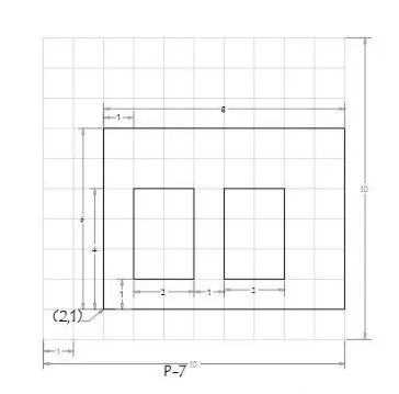
PROCEDURE:
- Create a new sheet in AutoCAD and set the required format for units of measure.
- Drawing this geometry by using the Absolute coordinates method.
- Select the line L tool from commands, toolbar, or draw menu.
- Give the reference point as (x,y) in the x and y-direction from the origin (0,0). The first point of the diagram is (2,1).
- The next point is (10,1).
- The next point is (10,7).
- The next point is (2,7).
- Next, use the close command by typing C in the command line and enter.
- The next point is (3,2).
- The next point is (5,2).
- The next point is (5,5).
- The next point is (3,5).
- Next, use the close command by typing C in the command line and enter.
- The next point is (6,2).
- The next point is (8,2).
- The next point is (8,5).
- The next point is (6,5).
- Finally use the close command by typing C in the command line and enter.
RESULT:
The diagram of the given plan is drawn by using the absolute coordinate system as per dimensions using the AutoCAD software.
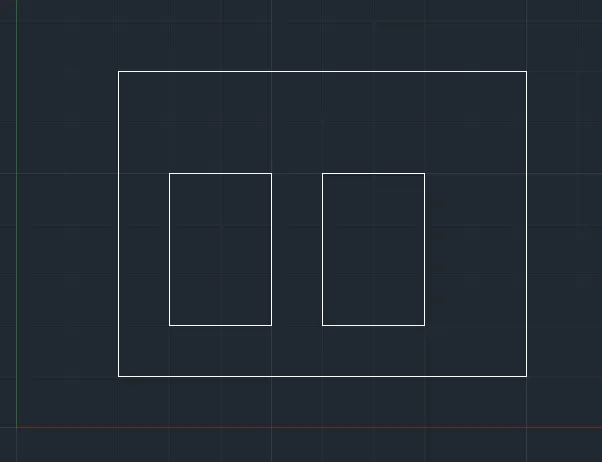
PROCEDURE:
- Create a new sheet in AutoCAD and set the required format for units of measure.
- Drawing this geometry by using the relative rectangle coordinates method.
- Select the line L tool from commands, toolbar, or draw menu.
- Give the reference point as (x,y) in the x and y-direction from the origin (0,0). The first point of the diagram is (2,1).
- The next point is (@8,0).
- The next point is (@0,6).
- The next point is (@-8,0).
- Next, use the close command by typing C in the command line and enter.
- The next point is (3,2).
- The next point is (@2,0).
- The next point is (@0,3).
- The next point is (@-2,0).
- Next, use the close command by typing C in the command line and enter.
- The next point is (6,2).
- The next point is (@2,0).
- The next point is (@0,3).
- The next point is (@-2,0).
- Finally use the close command by typing C in the command line and enter.
RESULT:
The diagram of the given plan is drawn by using the relative rectangle coordinate system as per dimensions, using the AutoCAD software.
PROCEDURE:
- Create a new sheet in AutoCAD and set the required format for units of measure.
- Drawing this geometry by using the relative polar coordinates method.
- Select the line L tool from commands, toolbar, or draw menu.
- Give the reference point as (x,y) in the x and y-direction from the origin (0,0). The first point of the diagram is (2,1).
- The next point is (@8<0°).
- The next point is (@6<90°).
- The next point is (@8<180°).
- Next, use the close command by typing C in the command line and enter.
- The next point is (3,2)
- The next point is (@2<0°)
- The next point is (@3<90°).
- The next point is (@2<180°).
- Next, use the close command by typing C in the command line and enter.
- The next point is (6,2).
- The next point is (@2<0°).
- The next point is (@3<90°).
- The next point is (@2<180°).
- Finally use the close command by typing C in the command line and enter.
RESULT:
The diagram of the given plan is drawn by using the relative polar coordinate system as per dimensions, using the AutoCAD software.
PROCEDURE:
- Create a new sheet in AutoCAD and set the required format for units of measure.
- Drawing this geometry by using the Direct distance entry method.
- Select the line L tool from commands, toolbar, or draw menu.
- Give the reference point as (x,y) in the x and y-direction from the origin (0,0). The first point of the diagram is (2,1).
- The next point: Position the cursor in the needed direction and then enter the distance 8.
- The next point: Position the cursor in the needed direction and then enter the distance 6.
- The next point: Position the cursor in the needed direction and then enter the distance 8.
- Next, use the close command by typing C in the command line and enter.
- The next point is (3,2)
- The next point: Position the cursor in the needed direction and then enter the distance 2.
- The next point: Position the cursor in the needed direction and then enter the distance 3.
- The next point: Position the cursor in the needed direction and then enter the distance 2.
- Next, use the close command by typing C in the command line and enter.
- The next point is (3,2)
- The next point: Position the cursor in the needed direction and then enter the distance 2.
- The next point: Position the cursor in the needed direction and then enter the distance 3.
- The next point: Position the cursor in the needed direction and then enter the distance 2.
- Finally use the close command by typing C in the command line and enter.
RESULT:
The diagram of the given plan is drawn by using the Direct distance entry method as per dimensions, using the AutoCAD software.
6)
AIM: To create the below geometry using all the coordinate system methods and by using the line tool.
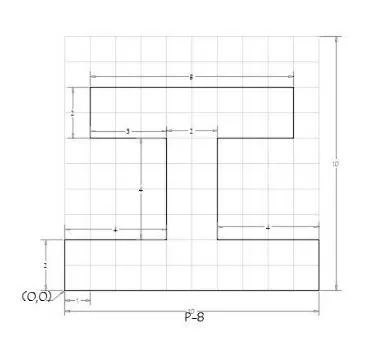
PROCEDURE:
- Create a new sheet in AutoCAD and set the required format for units of measure.
- Drawing this geometry by using the Absolute coordinates method.
- Select the line L tool from commands, toolbar, or draw menu.
- Give the reference point as (x,y) in the x and y-direction from the origin (0,0). The first point of the diagram is (0,0).
- The next point is (10,0).
- The next point is (10,2).
- The next point is (6,2).
- The next point is (6,6).
- The next point is (9,6).
- The next point is (9,8).
- The next point is (1,8).
- The next point is (1,6).
- The next point is (4,6).
- The next point is (4,2).
- The next point is (0,2).
- Finally use the close command by typing C in the command line and enter.
RESULT:
The diagram of the given plan is drawn by using the absolute coordinate system as per dimensions using the AutoCAD software.
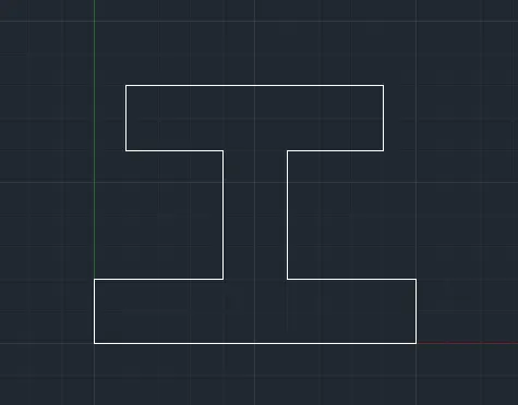
PROCEDURE:
- Create a new sheet in AutoCAD and set the required format for units of measure.
- Drawing this geometry by using the relative rectangle coordinates method.
- Select the line L tool from commands, toolbar, or draw menu.
- Give the reference point as (x,y) in the x and y-direction from the origin (0,0). The first point of the diagram is (0,0).
- The next point is (@10,0).
- The next point is (@0,2).
- The next point is (@-4,0).
- The next point is (@3,0).
- The next point is (@0,2).
- The next point is (@-8,0).
- The next point is (@0,-2).
- The next point is (@3,0).
- The next point is (@0,-4).
- The next point is (@-4,0).
- Finally use the close command by typing C in the command line and enter.
RESULT:
The diagram of the given plan is drawn by using the relative rectangle coordinate system as per dimensions, using the AutoCAD software.
PROCEDURE:
- Create a new sheet in AutoCAD and set the required format for units of measure.
- Drawing this geometry by using the relative polar coordinates method.
- Select the line L tool from commands, toolbar, or draw menu.
- Give the reference point as (x,y) in the x and y-direction from the origin (0,0). The first point of the diagram is (0,0).
- The next point is (@10<0°).
- The next point is (@2<90°).
- The next point is (@4<180°).
- The next point is (@4<90°).
- The next point is (@3<0°).
- The next point is (@2<90°).
- The next point is (@8<180°).
- The next point is (@2<270°).
- The next point is (@3<0°).
- The next point is (@4<270°).
- The next point is (@4<180°).
- Finally use the close command by typing C in the command line and enter.
RESULT:
The diagram of the given plan is drawn by using the relative polar coordinate system as per dimensions, using the AutoCAD software.
PROCEDURE:
- Create a new sheet in AutoCAD and set the required format for units of measure.
- Drawing this geometry by using the Direct distance entry method.
- Select the line L tool from commands, toolbar, or draw menu.
- Give the reference point as (x,y) in the x and y-direction from the origin (0,0). The first point of the diagram is (0,0).
- The next point: Position the cursor in the needed direction and then enter the distance 10.
- The next point: Position the cursor in the needed direction and then enter the distance 2.
- The next point: Position the cursor in the needed direction and then enter the distance 4.
- The next point: Position the cursor in the needed direction and then enter the distance 4.
- The next point: Position the cursor in the needed direction and then enter the distance 3.
- The next point: Position the cursor in the needed direction and then enter the distance 2.
- The next point: Position the cursor in the needed direction and then enter the distance 8.
- The next point: Position the cursor in the needed direction and then enter the distance 2.
- The next point: Position the cursor in the needed direction and then enter the distance 3.
- The next point: Position the cursor in the needed direction and then enter the distance 4.
- The next point: Position the cursor in the needed direction and then enter the distance 4.
- Finally use the close command by typing C in the command line and enter.
RESULT:
The diagram of the given plan is drawn by using the Direct distance entry method as per dimensions, using the AutoCAD software.
7)
AIM: To create the below geometry using all the coordinate system methods and by using the line tool.
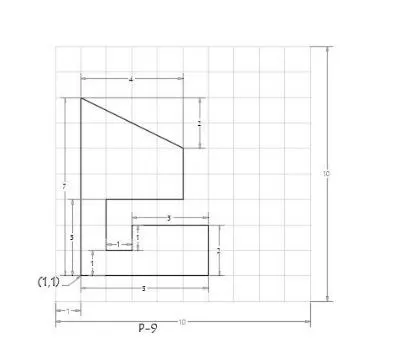
PROCEDURE:
- Create a new sheet in AutoCAD and set the required format for units of measure.
- Drawing this geometry by using the Absolute coordinates method.
- Select the line L tool from commands, toolbar, or draw menu.
- Give the reference point as (x,y) in the x and y-direction from the origin (0,0). The first point of the diagram is (1,1).
- The next point is (6,1).
- The next point is (6,3).
- The next point is (3,3).
- The next point is (3,2).
- The next point is (2,2).
- The next point is (2,4).
- The next point is (5,4).
- The next point is (5,6).
- The next point is (1,8).
- Finally use the close command by typing C in the command line and enter.
RESULT:
The diagram of the given plan is drawn by using the absolute coordinate system as per dimensions using the AutoCAD software.
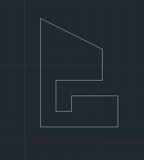
PROCEDURE:
- Create a new sheet in AutoCAD and set the required format for units of measure.
- Drawing this geometry by using the relative rectangle coordinates method.
- Select the line L tool from commands, toolbar, or draw menu.
- Give the reference point as (x,y) in the x and y-direction from the origin (0,0). The first point of the diagram is (1,1).
- The next point is (@5,0).
- The next point is (@0,2).
- The next point is (@-3,0).
- The next point is (@0,-1).
- The next point is (@-1,0).
- The next point is (@0,2).
- The next point is (@3,0).
- The next point is (@0,2).
- The next point is (@-4,2).
- Finally use the close command by typing C in the command line and enter.
RESULT:
The diagram of the given plan is drawn by using the relative rectangle coordinate system as per dimensions, using the AutoCAD software.
PROCEDURE:
- Create a new sheet in AutoCAD and set the required format for units of measure.
- Drawing this geometry by using the relative polar coordinates method.
- Select the line L tool from commands, toolbar, or draw menu.
- Give the reference point as (x,y) in the x and y-direction from the origin (0,0). The first point of the diagram is (2,1).
- The next point is (@5<0°).
- The next point is (@2<90°).
- The next point is (@3<180°).
- The next point is (@1<270°).
- The next point is (@1<180°).
- The next point is (@2<90°).
- The next point is (@3<0°).
- The next point is (@2<90°).
- The next point is (@4.47213595<156.4349488°).
- Finally use the close command by typing C in the command line and enter.
RESULT:
The diagram of the given plan is drawn by using the relative polar coordinate system as per dimensions, using the AutoCAD software.
PROCEDURE:
- Create a new sheet in AutoCAD and set the required format for units of measure.
- Drawing this geometry by using the Direct distance entry method.
- Select the line L tool from commands, toolbar, or draw menu.
- Give the reference point as (x,y) in the x and y-direction from the origin (0,0). The first point of the diagram is (1,1).
- The next point: Position the cursor in the needed direction and then enter the distance 5.
- The next point: Position the cursor in the needed direction and then enter the distance 2.
- The next point: Position the cursor in the needed direction and then enter the distance 3.
- The next point: Position the cursor in the needed direction and then enter the distance 1.
- The next point: Position the cursor in the needed direction and then enter the distance 1.
- The next point: Position the cursor in the needed direction and then enter the distance 2.
- The next point: Position the cursor in the needed direction and then enter the distance 3.
- The next point: Position the cursor in the needed direction and then enter the distance 2.
- The next point: Position the cursor in the needed direction and then enter the distance 4.47213595.
- Finally use the close command by typing C in the command line and enter.
RESULT:
The diagram of the given plan is drawn by using the Direct distance entry method as per dimensions, using the AutoCAD software.
8)
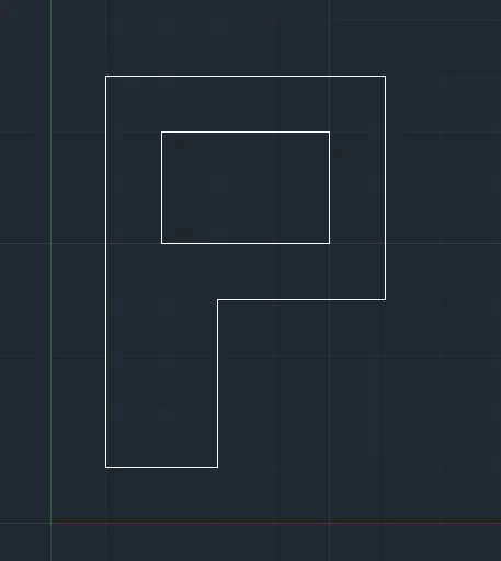
AIM: To create the below geometry using all the coordinate system methods and by using the line tool.
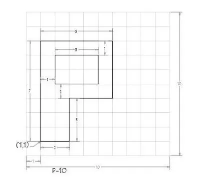
PROCEDURE:
- Create a new sheet in AutoCAD and set the required format for units of measure.
- Drawing this geometry by using the Absolute coordinates method.
- Select the line L tool from commands, toolbar, or draw menu.
- Give the reference point as (x,y) in the x and y-direction from the origin (0,0). The first point of the diagram is (1,1).
- The next point is (3,1).
- The next point is (3,4).
- The next point is (6,4).
- The next point is (6,8).
- The next point is (1,8).
- Next, use the close command by typing C in the command line and enter.
- The next point is (2,5).
- The next point is (5,5).
- The next point is (5,7).
- The next point is (2,7).
- Finally use the close command by typing C in the command line and enter.
RESULT:
The diagram of the given plan is drawn by using the absolute coordinate system as per dimensions using the AutoCAD software.
PROCEDURE:
- Create a new sheet in AutoCAD and set the required format for units of measure.
- Drawing this geometry by using the relative rectangle coordinates method.
- Select the line L tool from commands, toolbar, or draw menu.
- Give the reference point as (x,y) in the x and y-direction from the origin (0,0). The first point of the diagram is (1,1).
- The next point is (@2,0).
- The next point is (@0,3).
- The next point is (@3,0).
- The next point is (@0,4).
- The next point is (@-5,0).
- Next, use the close command by typing C in the command line and enter.
- The next point is (2,5).
- The next point is (@3,0).
- The next point is (@0,2).
- The next point is (@-3,0).
- Finally use the close command by typing C in the command line and enter.
RESULT:
The diagram of the given plan is drawn by using the relative rectangle coordinate system as per dimensions, using the AutoCAD software.
PROCEDURE:
- Create a new sheet in AutoCAD and set the required format for units of measure.
- Drawing this geometry by using the relative polar coordinates method.
- Select the line L tool from commands, toolbar, or draw menu.
- Give the reference point as (x,y) in the x and y-direction from the origin (0,0). The first point of the diagram is (1,1).
- The next point is (@2<0°).
- The next point is (@3<90°).
- The next point is (@3<0°).
- The next point is (@4<90°).
- The next point is (@5<180°).
- Next, use the close command by typing C in the command line and enter.
- The next point is (2,5).
- The next point is (@3<0°).
- The next point is (@2<90°).
- The next point is (@3<180°).
- Finally use the close command by typing C in the command line and enter.
RESULT:
The diagram of the given plan is drawn by using the relative polar coordinate system as per dimensions, using the AutoCAD software.
PROCEDURE:
- Create a new sheet in AutoCAD and set the required format for units of measure.
- Drawing this geometry by using the Direct distance entry method.
- Select the line L tool from commands, toolbar, or draw menu.
- Give the reference point as (x,y) in the x and y-direction from the origin (0,0). The first point of the diagram is (1,1).
- The next point: Position the cursor in the needed direction and then enter the distance 2.
- The next point: Position the cursor in the needed direction and then enter the distance 3.
- The next point: Position the cursor in the needed direction and then enter the distance 3.
- The next point: Position the cursor in the needed direction and then enter the distance 4.
- The next point: Position the cursor in the needed direction and then enter the distance 5.
- Next, use the close command by typing C in the command line and enter.
- The next point is (2,5).
- The next point: Position the cursor in the needed direction and then enter the distance 3.
- The next point: Position the cursor in the needed direction and then enter the distance 2.
- The next point: Position the cursor in the needed direction and then enter the distance 3.
- Finally use the close command by typing C in the command line and enter.
RESULT:
The diagram of the given plan is drawn by using the Direct distance entry method as per dimensions, using the AutoCAD software.
9)
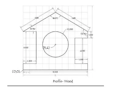
AIM: To create the below geometry using all the coordinate system methods and by using the line tool.
PROCEDURE:
- Create a new sheet in AutoCAD and set the required format for units of measure.
- Drawing this geometry by using the Absolute coordinates method.
- Select the line L tool from commands, toolbar, or draw menu.
- Give the reference point as (x,y) in the x and y-direction from the origin (0,0). The first point of the diagram is (0,0).
- The next point is (10,0).
- The next point is (10,1).
- The next point is (8,1).
- The next point is (8,5).
- The next point is (10,5).
- The next point is (10,6).
- The next point is (5,9).
- The next point is (0,6).
- The next point is (2,6).
- The next point is (2,1).
- The next point is (0,1).
- Next, use the close command by typing C in the command line and enter.
- Select the circle from the draw panel and select the centre radius.
- Select the centre point (5,4) to draw the circle.
- Select the radius in the command line and enter the value 2 radii of the circle.
RESULT:
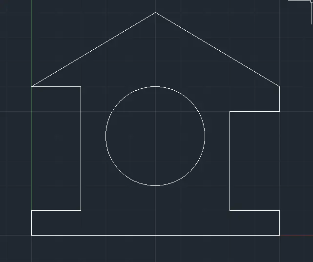
The diagram of the given plan is drawn by using the absolute coordinate system as per dimensions using the AutoCAD software.
10)
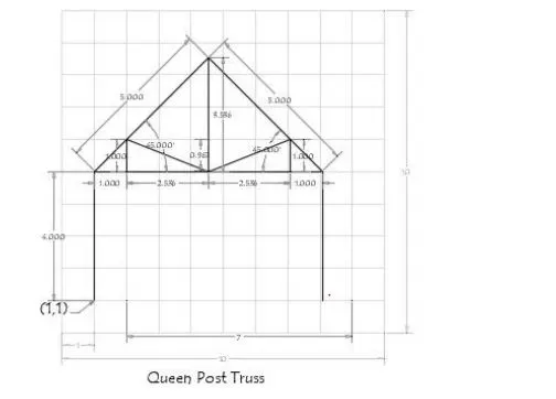
AIM: To create the below geometry using all the coordinate system methods and by using the line tool.
PROCEDURE:
- Create a new sheet in AutoCAD and set the required format for units of measure.
- Drawing this geometry by using the coordinate system method.
- Select the line L tool from commands, toolbar, or draw menu.
- Give the reference point as (x,y) in the x and y-direction from the origin (0,0). The first point of the diagram is (1,1).
- The next point is (@4<90°).
- The next point is (@5<45°).
- The next point is (@5<315°).
- The next point is (@4<270°).
- The next point is (1,5).
- The next point is (@8.072<0°).
- The next point is (@4.536,5).
- The next point is (@3.536<90°).
- The next point is (2,5).
- The next point is (@1<90°).
- The next point is (@4.539,5).
- The next point is (7.072,5).
- The next point is (@1<90°).
- The next point is (4.539,5).
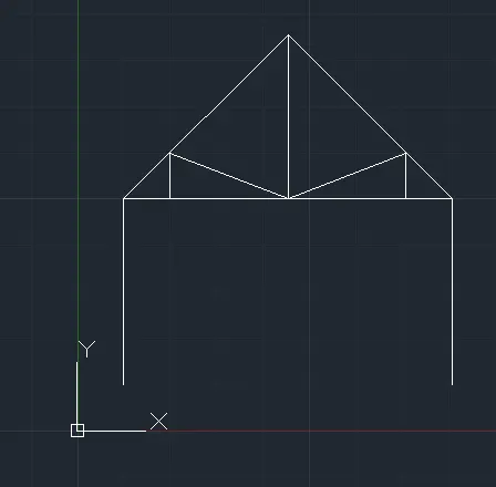
RESULT:
The diagram of the given plan is drawn by using the coordinate system as per dimensions using the AutoCAD software.
11)
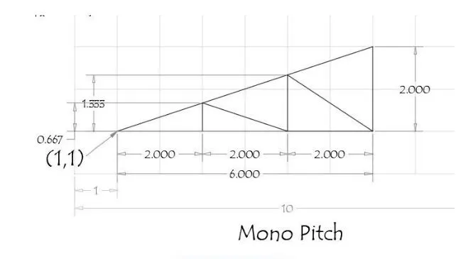
AIM: To create the below geometry using all the coordinate system methods and by using the line tool.
PROCEDURE:
- Create a new sheet in AutoCAD and set the required format for units of measure.
- Drawing this geometry by using the coordinate system method.
- Select the line L tool from commands, toolbar, or draw menu.
- Give the reference point as (x,y) in the x and y-direction from the origin (0,0). The first point of the diagram is (1,1).
- The next point is (7,1).
- The next point is (7,3).
- Next, use the close command by typing C in the command line and enter.
- The next point is (3,1).
- The next point is (@0.667<90°).
- The next point is (5,1).
- The next point is (@1.333<90°).
- The next point is (7,1).
RESULT:
The diagram of the given plan is drawn by using the coordinate system as per dimensions using the AutoCAD software.