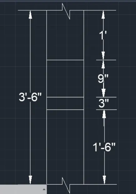
Creation of Column Schedule and Drawing Template using AutoCad
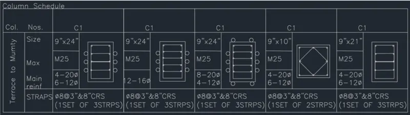
1. Create a column schedule as shown in the figure.
Note: Create a column schedule with the help of lines. Also, insert text with the help of Dtext command or Single Line text.
Hint: Use font name: romans.shx; Height: 8”, Justify: Left
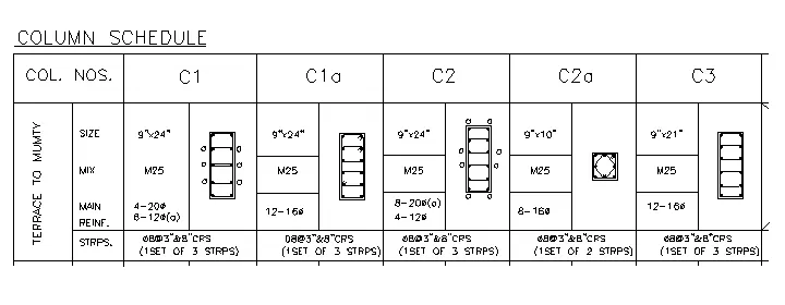
AIM: TO CREATE A COLUMN SCHEDULE.
INTRODUCTION: In in given table, a bar bending schedule of column of size 9"x24" are given including dia, length details.
commands used are- lines and circle for column drawing and table command for bar bending schedule.
from the table given,
- C1 column is provided with 6 bars of 12mm dia and 4 bars of 20 mm dia, 12mm is mentioned as "a".
- C1a column is provided with 12 bars of 16mm dia.
- C2 column is provided with 8 bar of 20mm dia and 4 bars of 12mm dia.
- C2a column is provided with 12 bars of 16mm dia.
- C3 column is provided with 12 bar of 16mm dia.
- lets assume column cover as 2"(approx 50mm).
PROEDURE:
- for drafting of C1 column:
- set the units as enfineering with O precision
- select LINE command from draw pannel and specify a corner point.
- specify first coordinate as 24" @ +ve y-axis.
- specify next coordinate as 9" @ +ve x-axis.
- specify nextcoordinate as 24" @ -ve y-axis.
- click for close command.
- provide lightweight for column of 0.30mm and select display buttom in setting.
- divide column into 4 parts at distance of 6".
- select circle with daimeter, draw two circles of dia 0.7874 and 0.4725 inches.
- copy paste at required edges of columns.
- similarly follow same procedure for remaining column making.
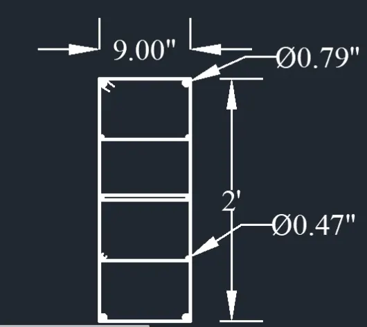
- For C1a column, circle with diameter 0.63 and divide into 5 lines.
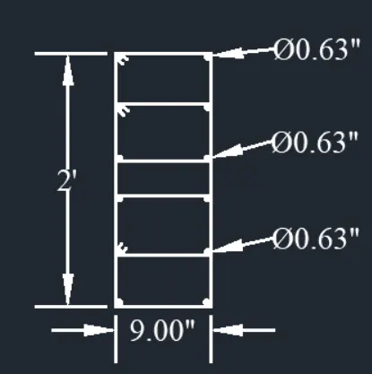
- For C2 column, circle with dia 0.787 and 0.434 at given place.
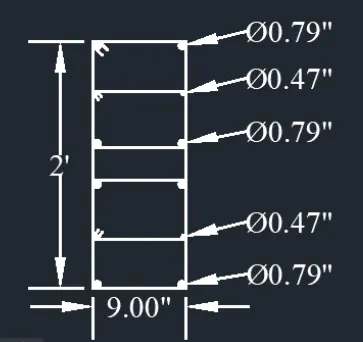
- For C2a make a rectangle of 10"×9" and circle of dia 0.79.
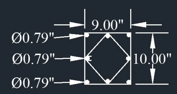
- Making C3 is similar to C1 column but rebar dia is 0.63
- select a table command from annotation panel, specify in text edit style as time new roman and height 2".
- enter rows as 4 and columns as 12.
- merge the required cells by selecting them and merge option on table edit.
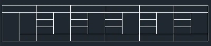
- Enter the data of column details.
- Select column drafted and move to required cell.
RESULT:
2. Create a window schedule as shown in the figures:
Window Schedule:
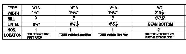
AIM: TO CREATE A WINDOW SCHEDULE
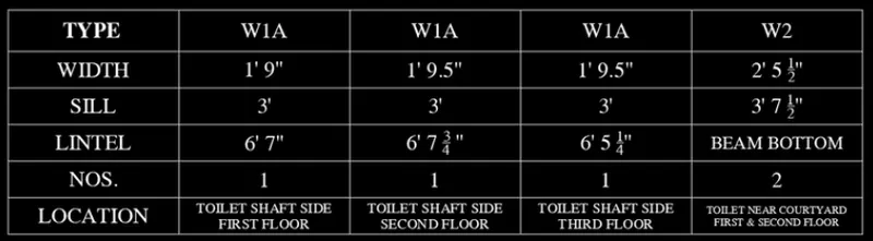
INTRDOUCTION: The given table consists of details of different windows. Details holds its width, silla and lintel with number of windows of that type and location of placing windows.
PROCEDURE:
- enter TAb for table option,set row=6 and column-5 with title head deleted.
- set text style AS TIMES NEW ROMAN,height AS 2" in tableedit option and justification middle centre.
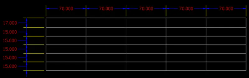
- click on particular cell and type the given information.
RESULT:
3. Create the drawing template as shown in the figure:< Use the Notes as in the figure>
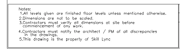

AIM: TO CREATE THE DRAWING TEMPLATE
INTRODUCTION: drawing template depends on type of drawing provided like it varies for architecural,electrical,water supply etc..
It holds the notes which required to be followed during construction.
Also holds details like project name, adress, date, architect name, company name etc., like making a plot,drafting are placed inside drawing template.
PROCEDURE:
- Select table from annotation tool bar and set text style as time new roman with text height and justification as 1" and middle center.
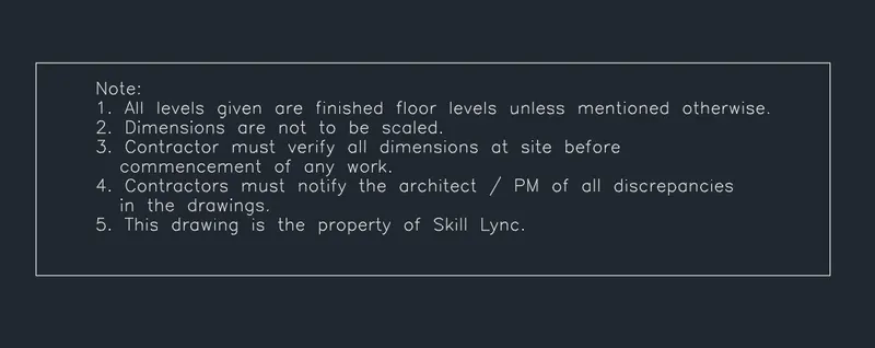
- set rows as 2 and column 1 for middle table portion.
- repeat the table command, set rows-4 and column 3 and place next to previous column.
- now draw a rectangle of same height as table with certain distance.
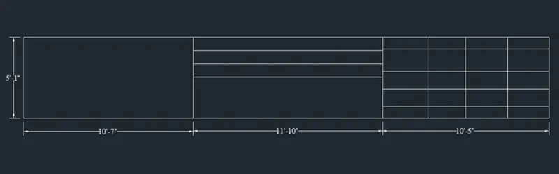
- Use multiline test command for notes content in left box with text height-8"
- Enter the data in cell.
- Select cell to be merged in the right table.
RESULT:

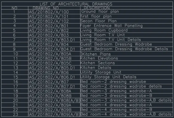
4. Create the list of drawing schedule as shown in the figure:
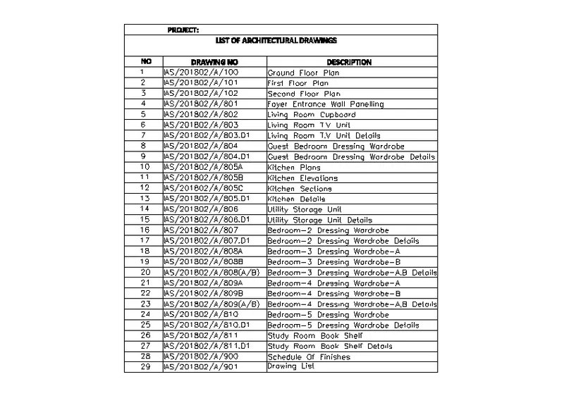
AIM: TO CREATE THE LIST OF DRAWING SCHEDULE
INTRODUCTION: The given table consist of list of architecural drawing with specified drawing nubers and description, which helps during planning and constrcution process.
PROCEDURE:
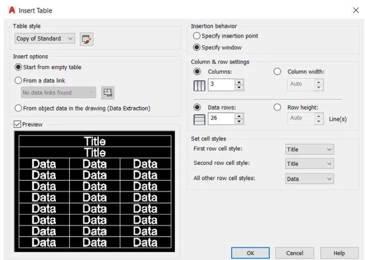
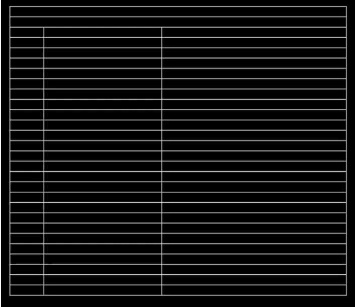
- enter TAB for table option and edit as per required.
- click on first line (Title)add insert below line option..
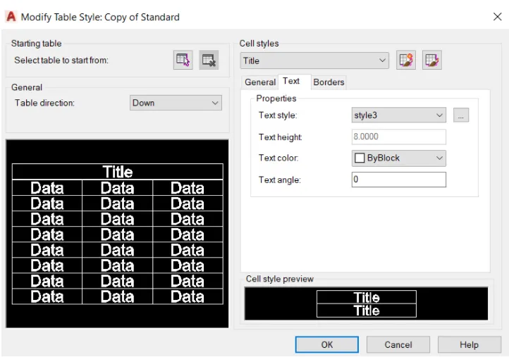
- Enter the given data using text option
- To copy paste property or text, scroll blue arrow head grid down.
RESULT:
5. Create the Beam detail as shown in the figure and provide text wherever given.
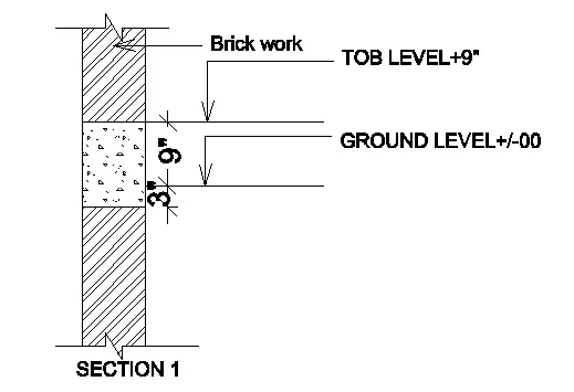
AIM : TO CREATE THE BEAM DETAIL
INTRODUCTION: the given drawing shows beam with brick work and levels.
PROCEDURE:
- enter L for line command and draw a horizontal line.
- repeat the command and draw a vertical line of height 3.6".
- offset the vertical line at distance of 9".
- offset horizontal line with distance 1.5,1.8,2.5' and 3.5
- provide the break line on both
- use LEADER command for test with arrow indication.
- enter H for hatchs-select AS132 for brick work with scale 10 and select pick point.
- similarly for Arc-CONC with scale factor-0.5
RESULT: