Creation of Column Schedule and Drawing Template using AutoCad
1. Create a column schedule as shown in the figure.
INTRODUCTION
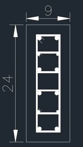
1. Column C1 is provided with 4 bars of 20 mm dia. and 6 bars of 12 mm dia. The 12 mm dia bars are marked with 'a'.
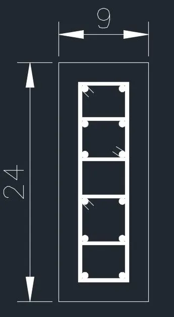
2. Column C1a and Column C3 are provided with 12 bars of 16 mm dia bars.
3. Column C2 is provided with 8 bars of 20 mm dia and 4 bars of 12 mm dia. The 20 mm dia bars are marked with 'a'.
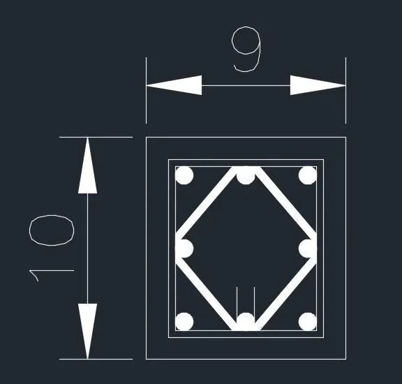
4. Column C2a is provided with 8 bars of 16 mm dia.
5. All columns are provided with 8 mm dia stirrups with 3" spacing c\c near the ends and 8" c\c in mid-length.
6. The clear cover for all the columns is assumed to be 1.5" (approx 40 mm). As per IS 256, the minimum cover to the column should not be less than 40 mm
PROCEDURE
1. Open a new AutoCAD file in Imperial units.
2. Convert the diameter of the bars into inches. Make a new text style with the font - romans.shx and height 8".
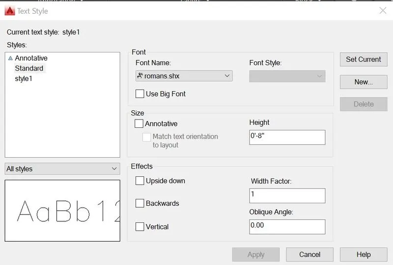
The following table contains conversion
(Divide by 25.4)
| Values in mm | Values in Inches |
| 20 | 0.7874 |
| 16 | 0.6299 |
| 12 | 0.4725 |
| 8 | 0.3150 |
The dimensions for the bars on the left are the same as that of the bars on the right. The longitudinal and stirrups are hatched with a white solid fill.
3. Make the column C1
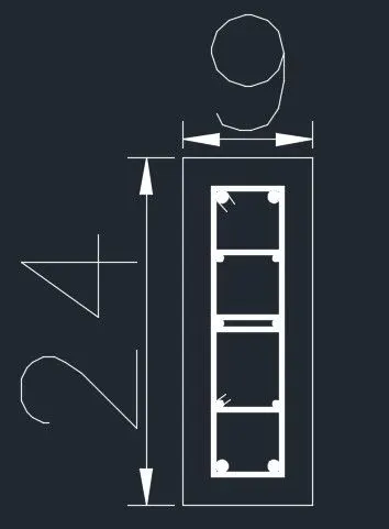
4. Make column C1a
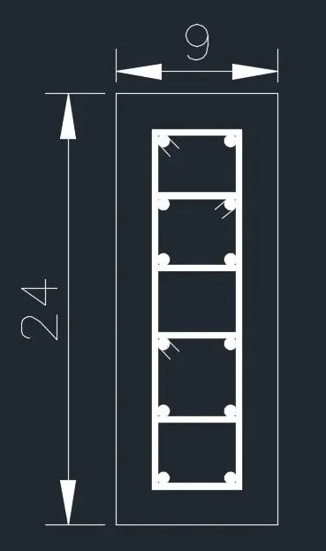
5. Make column C2
6. Make column C2a
7. Make column C3
RESULT:
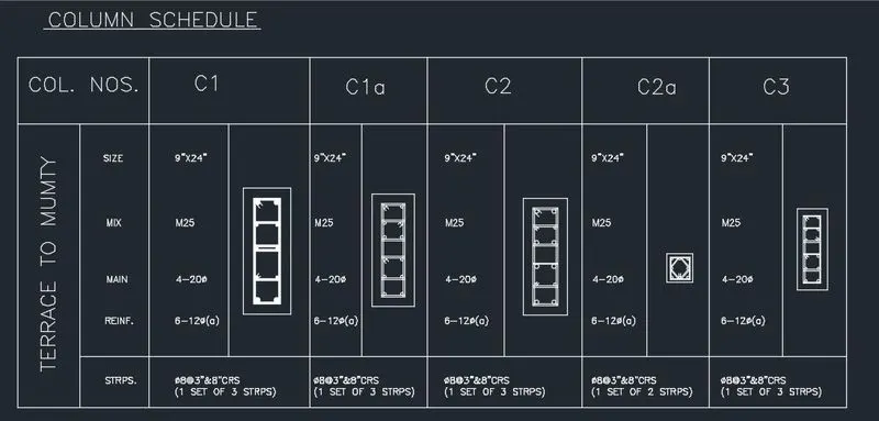
fill the table using single line text as shown. (Rotate "Terrace to mumty" by 90 degrees) and move the columns one by one to their respective places.
AIM To create a window schedule using the given table containing window, sill, lintel height for different types of beams.
PROCEDURE
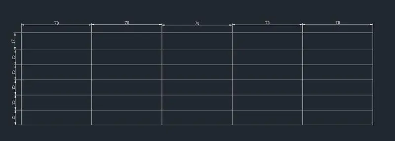
1. Draw the table.
2. Using DT command, write down all required data as given.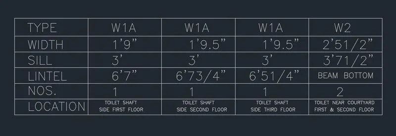
AIM To create the drawing template
PROCEDURE
1. Make the following table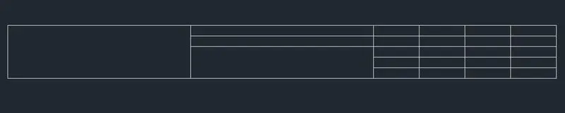
2. Using DT command write down all the required details as per given data and place them in their required positions. Use Text Height= 2.5 and Font = Arial. Trim the lines as required.

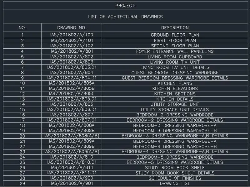
3. Draw the drawing schedule using Table command with the following values as below.
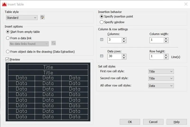
4. Edit and adjust the table and put in the details as per given data to get the result.
AIM To create the Beam using the values given
PROCEDURE
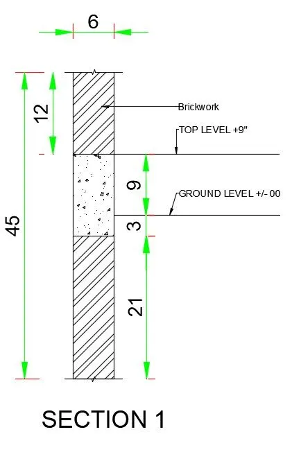
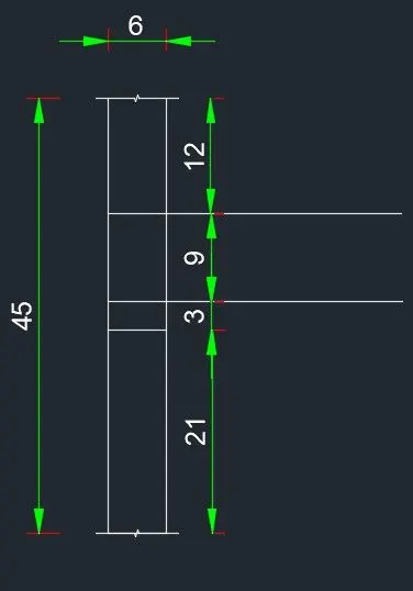
1. Draw two parallel lines 45" long at a distance of 6" from each other using line and offset command.
2. Using the breakline command, make a breakline at the top and bottom.
3. Make the horizontal lines as shown.
4. Using hatch command do the hatching of brickwork and concrete as shown.
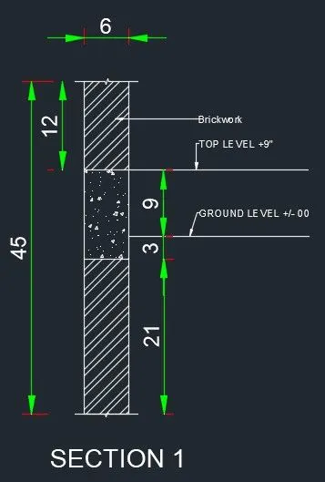
5. The result is shown below.