Creation of Column Schedule and Drawing Template using AutoCad
CHALLANGE-1
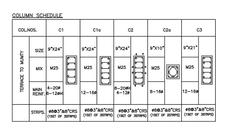
Q] Create a Column Schedule as Shown in Figure Below
Aim: To create a column schedule, and to draw the column showing reinforcement of the columns in detail.
Introduction:The column schedule is a schedule which the details of column will be collected in the construction for design purpose. The column
scheduling is very important thing in column detailing.
Commands used:
- Limits command
- Single Text command
- Line command
- Dimlinear command
- Trim command
- Mtext command
- Circle command
- object snap command
- DONUT command
- Divide command
- Offset command
- Units command
- Dimstyle command
- Extend command
- Mirror command
Procedure:
Step:-1
Column-1
- First off all we have to open the autocad and set the limits and units.
- First we have to draw the table using the line command as shown in below table.
- Next we need to enter the details of columns with Single text and Mtext command.
- Then again we draw the column with given details as shown in below figure.
- First we draw the line with the length of 9" horizontally.
- Next we draw the 24" line vertically, then again draw the line with the length of 9".
- Finally we join the first line and last line.
- Then after we do offset of 0.6", and do the offset to inside of rectangle we drawn previously.
- Next draw a circle beside of the previous figure , we take the circle diameter as 20mm
- And take another circle as diameter 12mm.
- Now use the divide command and give the 4 segments inside the rectangle.
- Now place the circle in the every segment.
- After putting the circles on one side, we use the mirror command.
- Mirror the one side fixed circles to other side.
- And put the 3 stirrups in the column where they are required to put in certain position.
- And Bend the corner of stirrups to the 45 degrees.
- And we denote the 12mm bars as "a", as shown in below figure.
- Next we have to the this overall column data in the table which we have draw first, as shown in below table.
Step:2
Column-1a
- Here we need to enter the details of columns with Single text and Mtext command.
- Then again we draw the column with given details as shown in below figure.
- First we draw the line with the length of 9" horizontally.
- Next we draw the 24" line vertically, then again draw the line with the length of 9".
- Finally we join the first line and last line.
- Then after we do offset of 0.6", and do the offset to inside of rectangle we drawn previously.
- Next draw a circle beside of the previous figure, we take the circle diameter as 16mm
- Now use the divide command and give the 5 segments inside the rectangle.
- Now place the circle in the every segment.
- After putting the circles on one side, we use the mirror command.
- Mirror the one side fixed circles to other side.
- And put the 3 stirrups in the column where they are required to put in certain position.
- And Bend the corner of stirrups to the 45 degrees, as shown in below figure
- Next we have to the this overall column data in the table which we have draw first.
- And the details entered in the table as shown in the below table.
Step:-3
Column-2
- Here we need to enter the details of columns with Single text and Mtext command.
- Then again we draw the column with given details as shown in below figure.
- First we draw the line with the length of 9" horizontally.
- Next we draw the 24" line vertically, then again draw the line with the length of 9"
- Finally we join the first line and last line.
- Then after we do offset of 0.6", and do the offset to inside of rectangle we drawn previously.
- Next draw a circle beside of the previous figure, we take the circle diameter as 20mm for 8 bars.
- And take another circle as diameter 12mm for 4 bars.
- Now use the divide command and give the 5 segments inside the rectangle.
- Now place the circle in the every segment.
- After putting the circles on one side, we use the mirror command.
- Mirror the one side fixed circles to other side.
- And put the 3 stirrups in the column where they are required to put in certain position.
- And Bend the corner of stirrups to the 45 degrees, as shown in below figure.
- And we denote the 20mm bars as "a", as shown in below figure.
- Next we have to the this overall column data in the table which we have draw first, as shown in below table.
Step:4
Column-2a
- Here we need to enter the details of columns with Single text and Mtext command.
- Then again we draw the column with given details as shown in below figure.
- First we draw the line with the length of 9" horizontally.
- Next we draw the 10" line vertically, then again draw the line with the length of 9"
- Finally we join the first line and last line.
- Then after we do offset of 0.6", and do the offset to inside of rectangle we drawn previously.
- Next draw a circle beside of the previous figure, we take the circle diameter as 16mm for 8 bars.
- Now use the divide command and give the 2 segments inside the rectangle.
- Now place the circle in the every segment.
- After putting the circles on one side, we use the mirror command
- Mirror the one side fixed circles to other side.
- Nd we have to put the 16mm bars in middle also.
- And put the 2 stirrups in the column where they are required to put in certain position.
- And Bend the corner of stirrups to the 45 degrees, as shown in below figure.
Step:-5
Column-3
- Now we need to enter the details of columns with Single text and Mtext command.
- Then again we draw the column with given details as shown in below figure.
- First we draw the line with the length of 9" horizontally.
- Next we draw the 24" line vertically, then again draw the line with the length of 9".
- Finally we join the first line and last line.
- Then after we do offset of 0.6", and do the offset to inside of rectangle we drawn previously.
- Next draw a circle beside of the previous figure , we take the circle diameter as 16mm
- Now use the divide command and give the 5 segments inside the rectangle.
- Now place the circle in the every segment.
- After putting the circles on one side, we use the mirror command.
- Mirror the one side fixed circles to other side.
- And put the 3 stirrups in the column where they are required to put in certain position.
- And Bend the corner of stirrups to the 45 degrees, as shown in below figure.
- Next we have to the this overall column data in the table which we have draw first, as shown in below table.
Result:
- The column schedule was created successfully in the autocad in detail.
- And we drawn the 5 columns and we entered their details in the table as shown in figure.
CHALLENGE-2
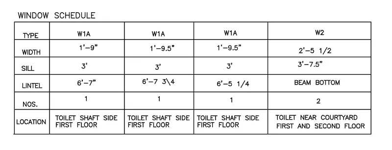
Q] Create a window Schedule as Shown in figure:
Aim: To create a window schedule, and to draw the details of windows for construction purpose.
Introduction:The window schedule is a schedule which the details of the windows in construction can be collected in the table form, that is why we collect the window details in the form table for the construction purposes.
Commands used:
- Limits command
- Single Text command
- Line command
- Dimlinear command
- Trim command
- Object snap command
- Offset command
- Units command
- Dimstyle command
- Extend command
Procedure:
Step:-1
- First off all we have to open the autocad and set the limits and units.
- Next we have to draw the table using the line command as shown in below table.
- We draw the 5 columns and the 6 rows for the window scheduling.
Step:-2
- Next we enter the details of the various windows in the window schedule
- And we draw the window schedule and enter the details of them in the tabular form.
- The window schedule with various window details was shown in below table.
Result:
• The window schedule was created successfully in the autocad in detail. . And we drawn the window schedule and written their details in the table as shown in figure.
CHALLENGE:-3
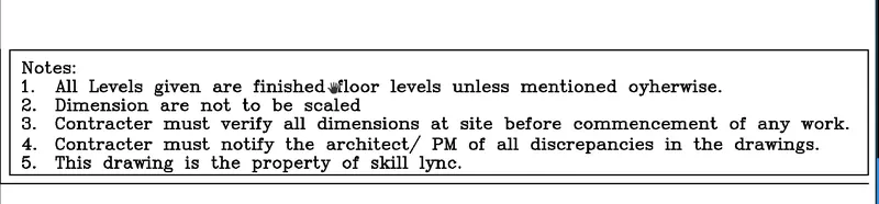
Q] Create a drawing template.
Aim: To create the drawing template for entering the details of the project.
Introduction: Drawing template files are drawings that store styles, settings, layers, and layouts in a drawing including title blocks. • When you create a new drawing based on a drawing template, the new drawing gets a copy of the styles in the template, but it is a one-time copy.
Commands used:
- Limits command
- Single Text command
- Line command
- Dimlinear command
- Trim command
- Object snap command
- Offset command
- Units command
- Dimstyle command
- Extend command
Procedure:
Step:-1
- First off all we have to open the autocad and set the limits and units.
- Next we have to draw the table using the line command as shown in below table.
- We draw this table for the entering the details of the entire project before submitting to the client.
- After entering the details of the we submit the drawings to the client.
Step:2
- After drawing the table we have to select the Mtecxt command to enter the notes and project details.
- And the text height will be kept to 8", and it is the standard text height for entering the details of the project in the table.
Result:
- The Drawing template was created successfully in the autocad in detail.
- And we drawn the drawing template and written their details in the tablular form as shown in figure.

CHALLENGE:-4
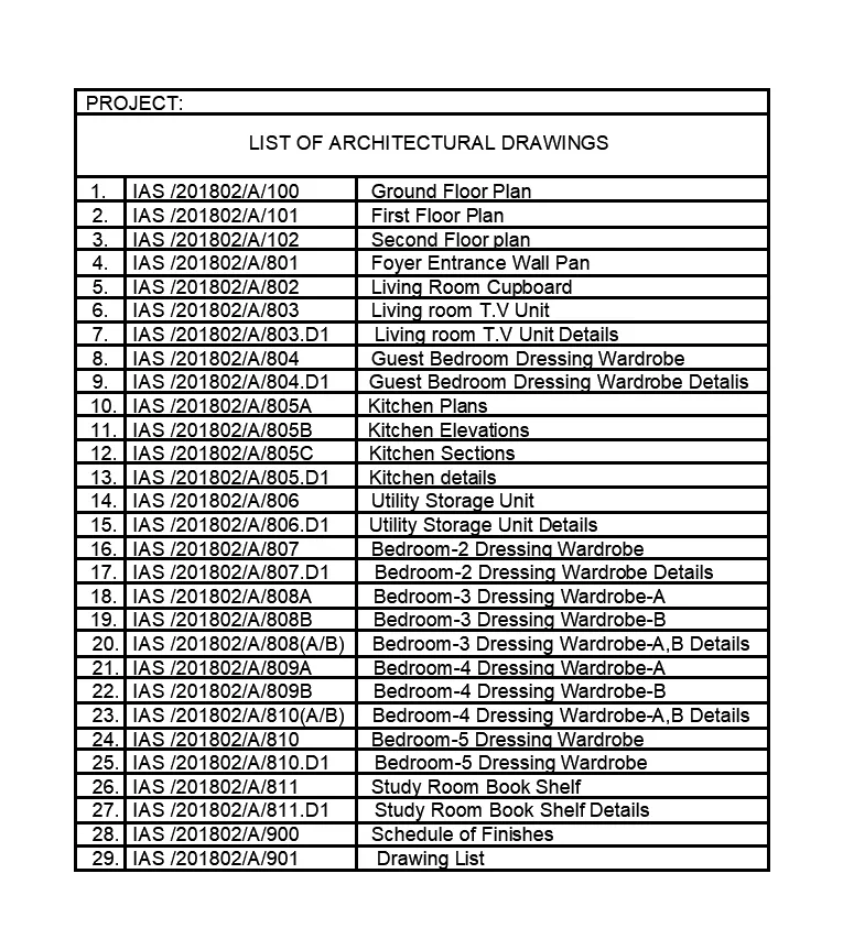
Q] Create the list of drawing schedule as shown in figure.
Aim: To create the list of drawing schedule and to be listed in detail.
Introduction: A schedule of drawings is an itemised list of drawings required for a building project. It can be included as part of an invitation to tender, or may be prepared as part of a design management plan. A schedule of drawings may include all the drawings required for a project, or on larger, more complex projects, it may be specifically prepared for a certain discipline, specialist or for a particular aspect of the works
Commands used:
- Limits command
- Table command
- Single text command
- Extend command
- Dimlinear command
Procedure:
Step:-1
- First off all we have to open the autocad and set the limits and units.
- Next we have to enter the Table command for creating the list of drawing schedules.
- After entering the table command the table setting screen will be displayed as shown in figure.
Step:2
- Next we use the single text command for texting in the table.
- After entering the details of list of drawing schedule,
- click on the outside of the table.
- Then the list of drawing schedule is listed in detail, as shown in below table.
Result:
- The List of Drawing Schedule was created successfully in the autocad in detail as shown in the given figure.
CHALLENGE-5
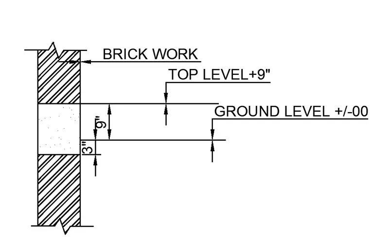
Q] Create the beam Details as Shown in the figureand frovided text for top level and ground level
Aim: To create the beam detail and provide text for the top level and ground level.
Introduction:A beam is a structural element that primarily resists loads applied laterally to the beam's axis. Its mode of deflection is primarily bybending. The loads applied to the beam result in reaction forces at the beam's support points. The total effect of all the forces acting on the beam is to produce shear forces and bending moments within the beams, that in turn
induce internal stresses, strains and deflections of the beam.
Commands used:
- Limits command
- Line command
- Dimlinear command
- Trim command
- Object snap command
- Offset command
- Units command
- Dimstyle command
- Extend command
- Leader command
Procedure:
Step:1
- First off all we have to open the autocad and set the limits and units.
- Next enter the line command and draw the line of length 4' vertically.
- Then again draw the line of length 9" horizontally forward.
- And next again draw the line of 4' length vertically upwards.
- Next draw the line horizontally backwards of length 9".
- Finally join the first line and the last line, then we will find the rectangle.
- Next from rigtht corner at bottom leave the distance of 1-5" upwards and draw a line from that distance, it is a ground level.
- Next from previous point we leave the distance of 9" and draw a line horizontally forward from that distance, that line we call the top level.
Step:-2
- Next here we have to put the dimentions for the ground level, its distance is 3"
- Next we have to put the dimensions from the ground level to the top level, the distance is 9".
- The beam with dimensions are shown in below figure.
Step:-3
- Then next we have to provide the texts for the particular parts, they are brick work, Top level and Ground level
- The beam with the texts mentioned are shown in below figure.
Step:-4
- Next we have to use the Hatch command to hatch the different parts in the diagram.
- The diagram hatched with various hatches with Hatch command as shown in the below figure.
Result:
The Beam detail with texts and dimensions are created successfully in the autocad in detail. . And we drawn the beam detail and written texts and dimensions in the detailed manner.
FINAL RESULT:
The given drawings and drawing schedules are successfully drawn in autocad in the detailed manner.