Creating various 3D Models like Furniture, Footing, Girder, Column drop with panel and Gable Wall in AutoCad
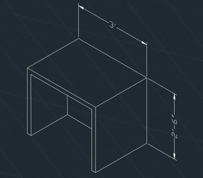
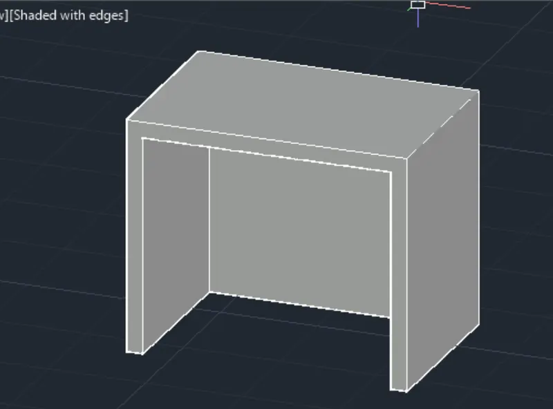
Q1. Create a 3D Furniture element as shown in the Figure. Assume dimensions which are missing.
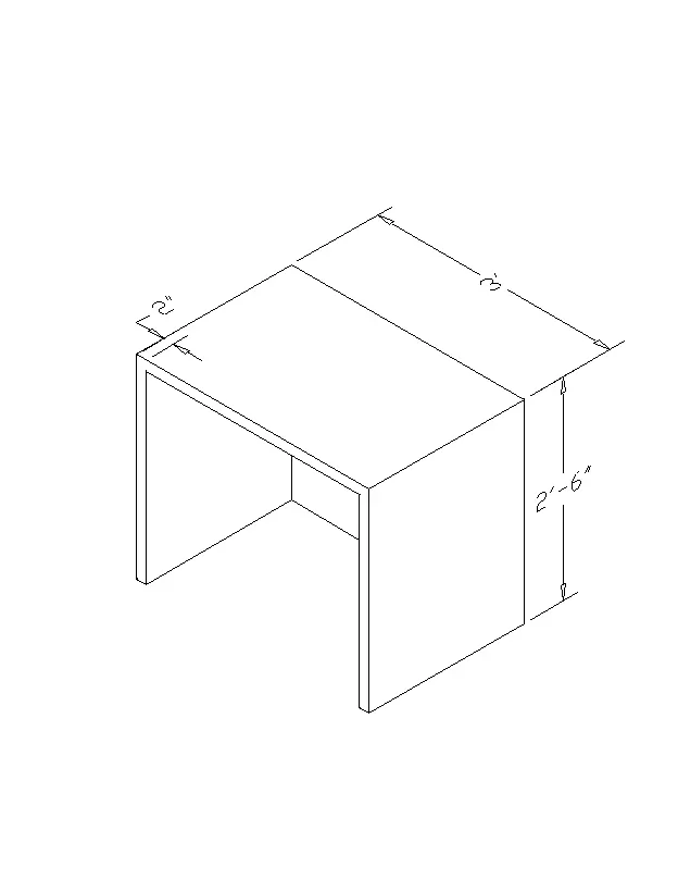
AIM: TO DRAW THE 3D WIREFRAME MODEL AS SHOWN FIGURE BY USING AUTOCAD TOOL
INTRODUCTION:
- THE 3D WIREFRAME MODEL GIVEN IS A FURNITURE EQUIPMENT IN THE HOUSE.
- THE 3D WIREFRAME MODEL IS DRAWN IN DIFFERENT COORDINATE SYSTEM SUCH AS RECTANGULAR COORDINATES
- SYSTEM, SPHERICAL COORDINATES SYSTEM, RELATIVE COORDINATE SYSTEM AND CYLINDRICAL COORDINATE SYSTEM.
PROCEDURE:
- OPEN AUTOCAD
- Command: UN UNITS
- Command: D DIMSTYLE
- Command: Regenerating model.
- _WSCURRENT
- Enter new value for WSCURRENT <"Drafting & Annotation">: 3D Modeling
- Command: Regenerating model.
- Command: L LINE
- Specify first point:
- Specify next point or [Undo]: 2¹
- Specify next point or [Undo]: 2'6"
- Specify next point or [Close/Undo]: 2'
- Specify next point or [Close/Undo]:c
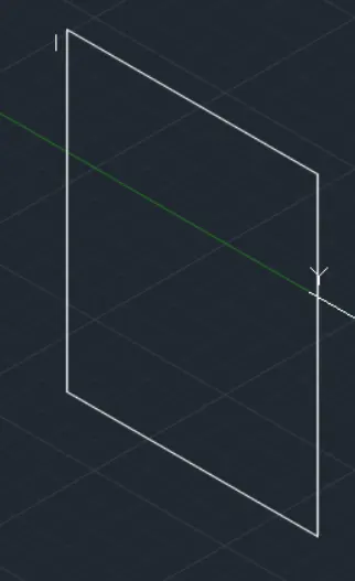
- Command: Regenerating model
- command: JJOIN
- Select source object or multiple objects to join at once: Specify
- opposite corner. 4 found
- Select objects to join:
- 4 objects converted to 1 3D polyline
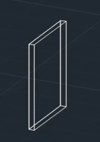
- Command: PRESSPULL
- Select object or bounded area:
- Specify extrusion height or [Multiple]:
- Specify extrusion height or [Multiple]:2"
- 1 extrusion(s) created
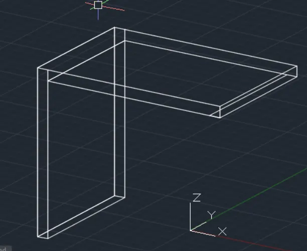
- Command LINE
- Command: L LINE
- Specify first point:
- Specify next point or [Undo]: 2"
- Specify next point or [Undo]:2'6"
- Specify next point or [Close/Undo]:
- Specify next point or [Close/Undo]: "Cancel"
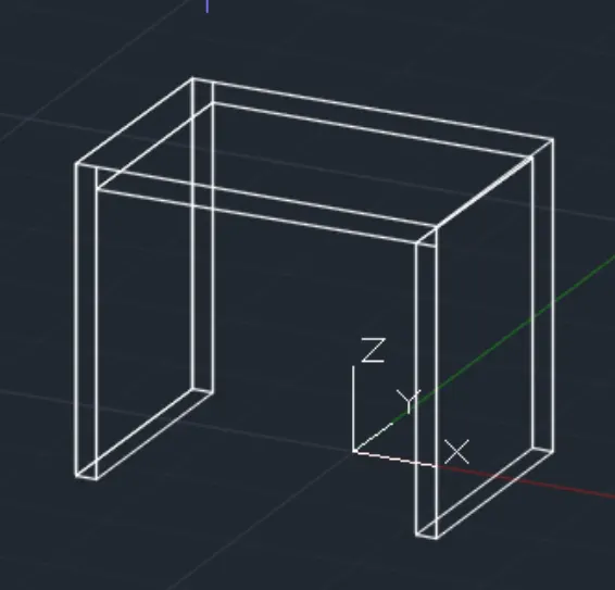
- Command: _presspull
- Select object or bounded area:
- Specify extrusion height or [Multiple]:
- Specify extrusion height or [Multiple]:2'10"
- 1 extrusion(s) created
- Select object or bounded area:
- Command: L LINE
- Specify first point:
- Specify next point or [Undo]: 2"
- Specify next point or [Undo]:
- Specify next point or [Close/Undo]: "Cancel"
- Command: PRESSPULL
- Select object or bounded area:
- Specify extrusion height or [Multiple]:
- Specify extrusion height or [Multiple]:
- 1 extrusion(s) created
- Select obiect.or bounded area:
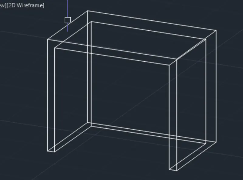
RESULT:
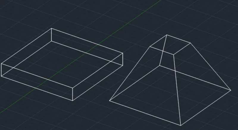
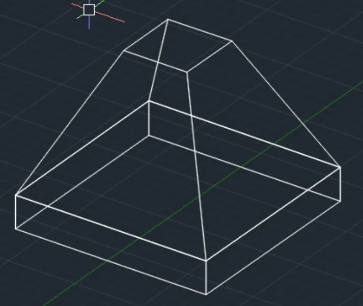
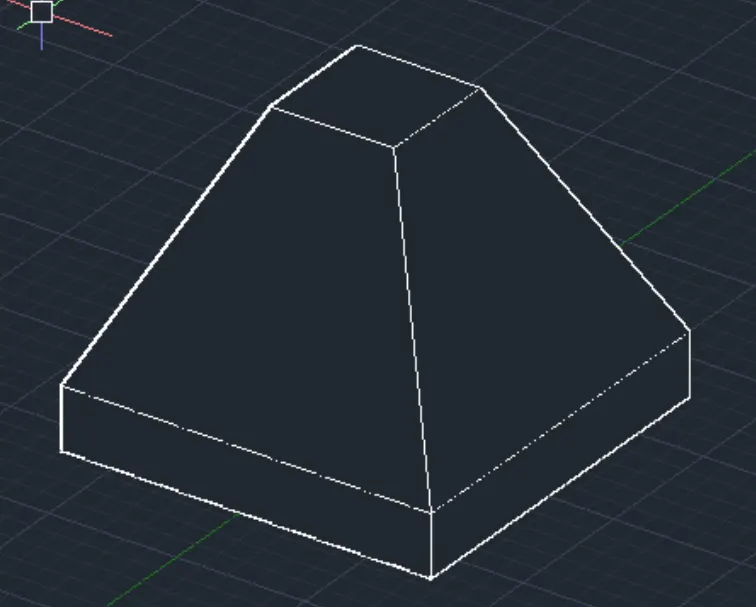
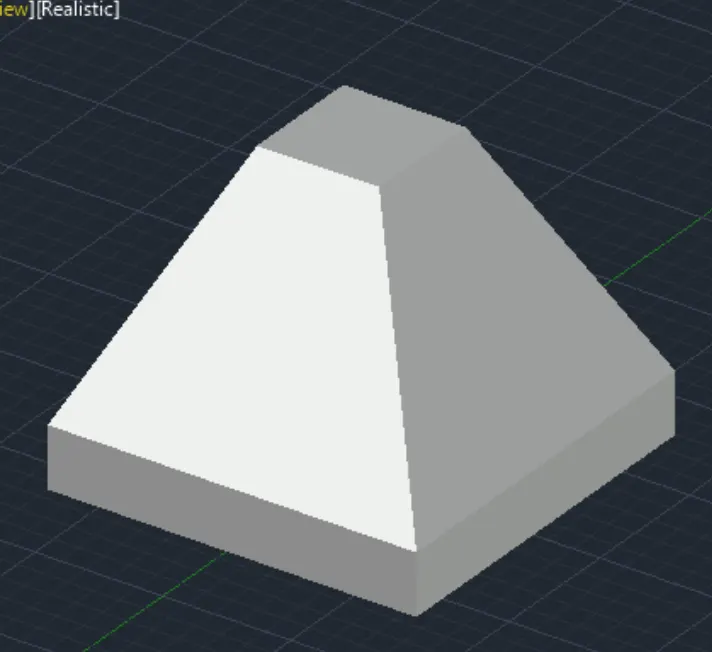
Q2. Create the 3d Model of an Isolated footing as shown in Figure.
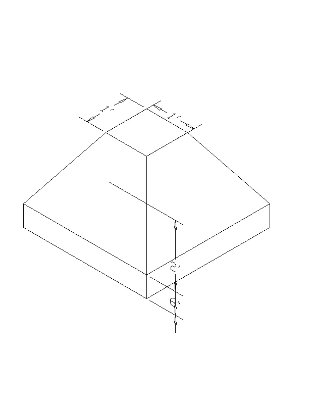
AIM: TO DRAW THE 3D WIREFRAME MODEL OF AN ISOLATED FOOTING AS SHOWN FIGURE BY USING AUTOCAD TOOL
INTRODUCTION :
- THE 3D MODEL GIVEN IS AN ISOLATED FOOTING.
- AN ISOLATED FOOTING IS USED TO SUPPORT A SINGLE COLUMN.
- ISOLATED FOOTINGS ARE INDEPENDENT FOOTINGS WHICH ARE PROVIDED FOR EACH COLUMN.
- BECAUSE OF ITS SIMPLICITY AND ECONOMICAL NATURE, IT IS MOST COMMONLY USED REINFORCEMENT FOOTING.
- THIS 3D MODEL IS OF TRAPEZOIDAL TAPERED ISOLATED FOOTING.
PROCEDURE:
- OPEN AUTOCAD
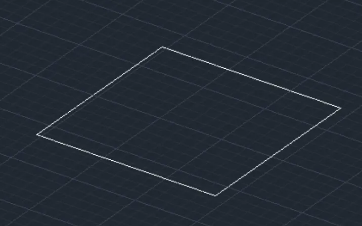
- Command: L LINE
- Specify first point:
- Specify next point or [Undo]: 3'
- Specify next point or [Undo]: 3¹
- Specify next point or [Close/Undo]: 3
- Specify next point or [Close/Undo]: c
- Command: JJOIN
- Select source object or multiple objects to join at once: Specify opposite corner: 4 found
- Select objects to join:
- 4 objects converted to 1 polyline
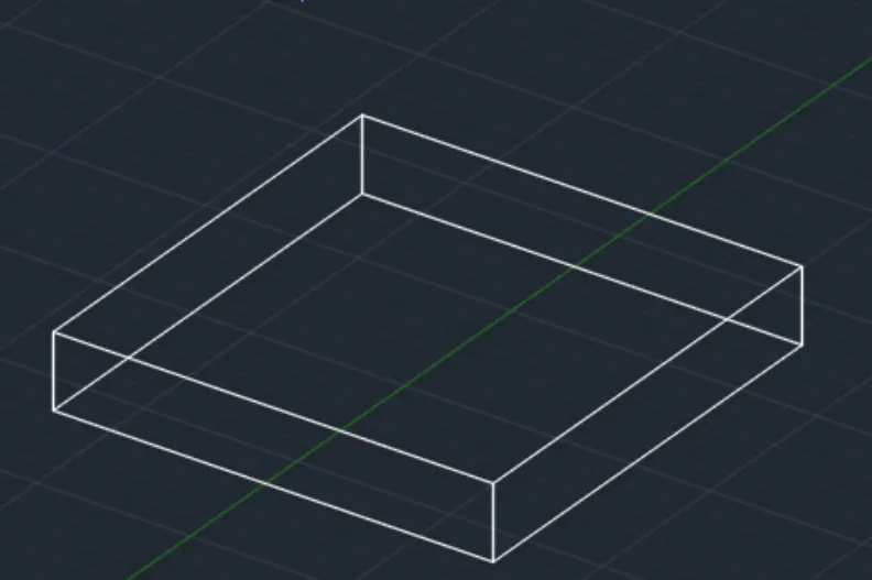
- Command: PRESSPULL
- Select object or bounded area:
- Specify extrusion height or [Multiple]: Specify extrusion height or [Multiple]:6
- 1 extrusion(s) created
- Select object or bounded area:
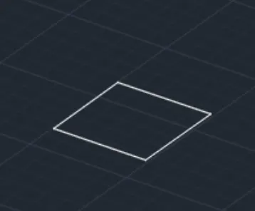
- Command: I LINE
- Specify first point:
- Specify next point or [Undo]: 1
- Specify next point or [Undo]: 1
- Specify next point or [Close/Undo]: 1
- Specify next point or [Close/Undo]: c
- Command: Specify opposite corner or [Fence/WPolygon/CPolygon]:
- Command: JJOIN 4 found
- 4 objects converted to 1 polyline
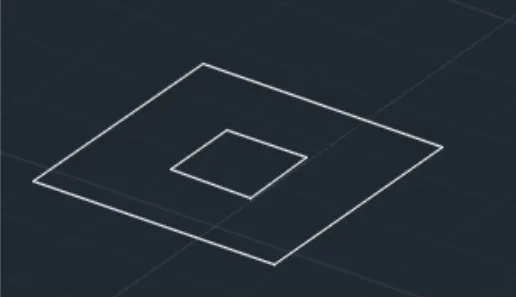
- Command: M MOVE 1 found
- Specify base point or [Displacement]:
- Specify second point or: 2
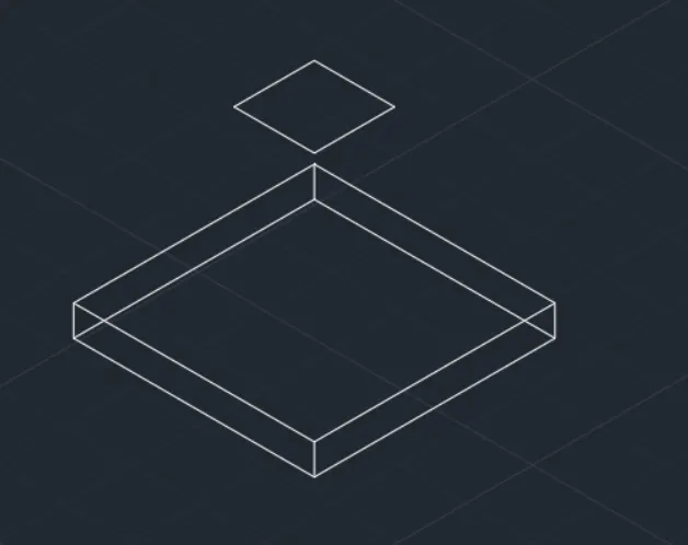
- Command: LOFT
- Current wire frame density: ISOLINES-4. Closed profiles creation mode - Solid
- Select cross sections in lofting order or [POint/join multiple edges/Mode]: 1 found Select cross sections in lofting order or [POint/Join multiple edges/MOde]: 1 found, 2 total
- Select cross sections in lofting order or [POint/Join multiple edges/MOde]
- 2 cross sections selected
- Enter an option [Guides/Path/Cross sections only/Settings]:
- Command: m MOVE 1 found
- Specify base point or [Displacement]:
- Specify second point or :
- Command: UNI UNION
- Select objects: 1 found
- Select objects: 1 found, 2 total
- Select objects:
RESULT:
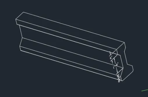
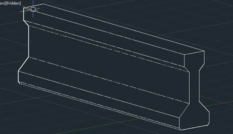
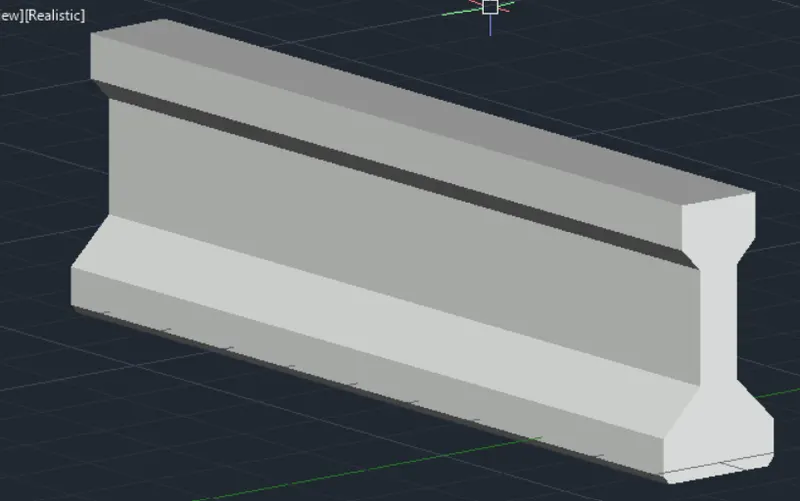
Q3. Create the 3D view of the AASTHO Type Girder.
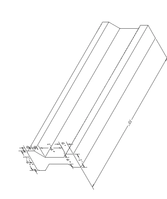
AIM: TO DRAW THE 3D WIREFRAME MODEL OF AN AASTHO TYPE GIRDER AS SHOWN FIGURE BY USING AUTOCAD TOOL
INTRODUCTION:
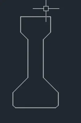
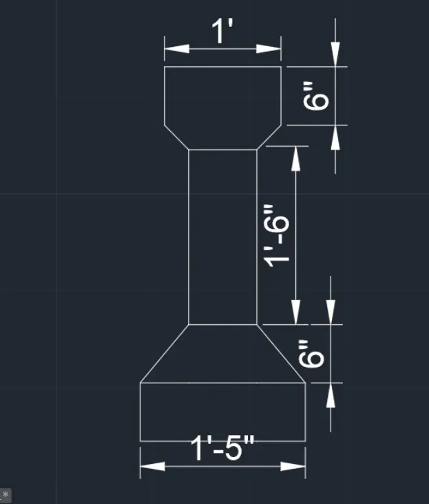
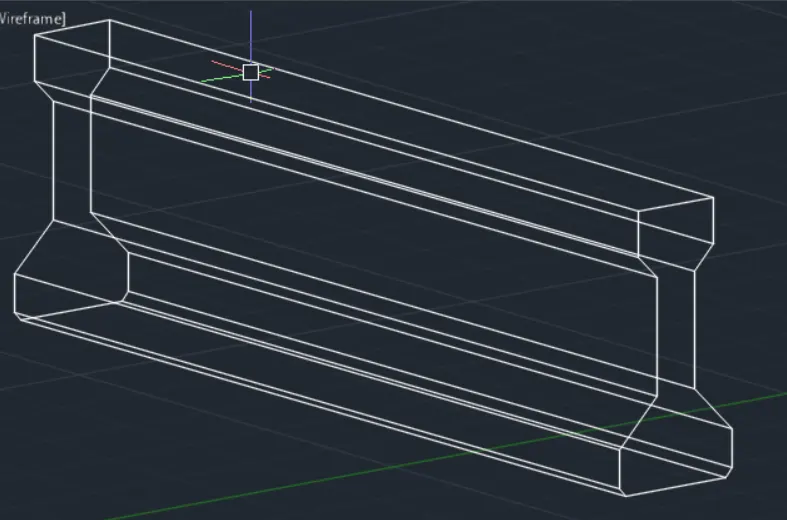
THE 3DMODEL GIVEN IS AN AASHTO TYPE GIRDER I SECTION. AASHTO GIRDERS ARE CLASSIFIED INTO 5 DIFFERENT
TYPES DEPENDING ON THEIR DIMENSIONS OF FLANGE AND WEB. FOLLOWING FIGURE SHOWS THE TYPES OF AASHTO-I BEAMS AT DIFFERENT DIMENSIONS. AS PER THE DIMENSIONS OF THE GIVEN FIGURE THE AASHTO GIRDER TYPE IS II.
PROCEDURE:
- Command: L LINE
- Specify first point:
- Specify next point or [Undo]: 3¹
- Specify next point or [Undo]: 3¹
- Specify next point or [Close/Undo]: 3'
- Specify next point or [Close/Undo]: c
- Command: JJOIN
- Select source object or multiple objects to join at once: Specify opposite corner: 4 found
- Select objects to join:
- Command: PRESSPULL
- Select object or bounded area:
- Specify extrusion height or [Multiple]:
- Specify extrusion height or [Multiple]:6
- 1 extrusion(s) created
- Select object or bounded area:
- Command: I LINE
- Specify first point
- Specify next point or [Undo]: 1'
- Specify next point or [Undo]: 1¹
- Specify next point or [Close/Undo]: 1'
- Specify next point or [Close/Undo].c
- Command: Specify opposite corner or [Fence/WPolygon/CPolygon]:
- Command: JJOIN 4 found
- 4 objects converted to 1 polyline
- Command: M MOVE 1 found
- Specify base point or [Displacement]:
- Specify second point or : 2'
- Command: LOFT
- Current wire frame density: ISOLINES-4, Closed profiles creation mode = Solid
- Select cross sections in lofting order or [POint/Join multiple edges/MOde]: 1 found
- Select cross sections in lofting order or [POint/Join multiple edges/MOde]: 1 found, 2 total Select cross sections in lofting order or [POint/Join multiple edges/MOde]:
- 2 cross sections selected
- Enter an option [Guides/Path/Cross sections only/Settings]:
- Command: m MOVE 1 found
- Specify base point or [Displacement]:
- Specify second point or :
- Command: UNI UNION
- Select objects: 1 found
- Select objects: 1 found, 2 total
- Select objects:
RESULT:
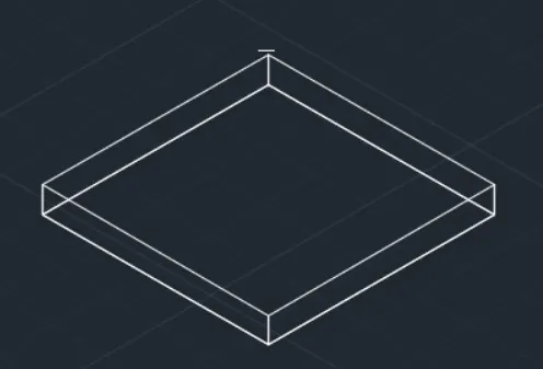
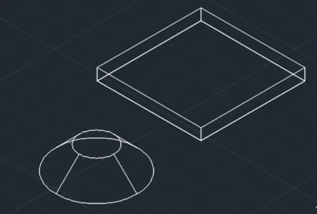
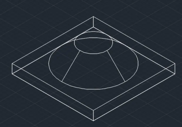
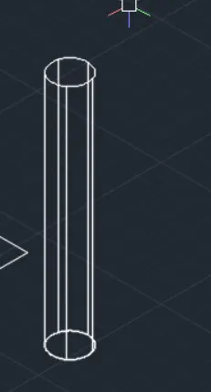
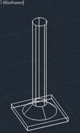
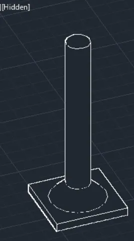
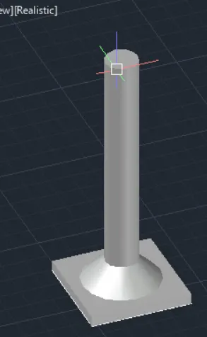
Q4. Create a 3d Model of a drop column with panel as shown in section and isometric view.
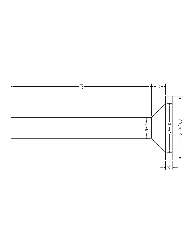
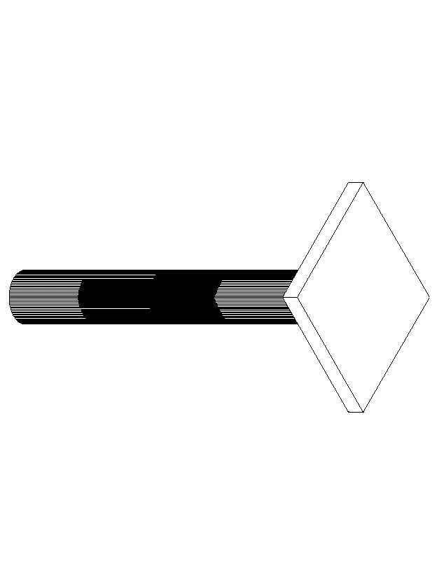
AIM: TO DRAW THE 3D WIREFRAME MODEL OF A DROP COLUMN AS SHOWN FIGURE BY USING AUTOCAD TOOL
INTRODUCTION:
- THE 3D MODEL GIVEN IS A DROP COLUMN USED FOR CONSTRUCTION OF FLAT SLABS.
- A DROP COLUMN IS USED WHEN BEAM IS NOT REQUIRED IN THE DESIGN.
- DROP IS A PART OF THE SLAB AROUND THE COLUMN, WHICH HAVE GREATER THICKNESS THAN THE REST OF THE SLAB.
- THE DROP COLUMN NOT ONLY ELIMINATES THE NEED OF BEAM BUT ALSO GIVES A PLAIN CEILING AND GREAT APPETENCE, BETTER LIGHT
- DIFFUSION, MORE OPEN ROOMS.
FLAT SLAB IS DESING BY TWO METHODS
1. DIRECT DESING METHOD.
2. EQUIVALENT FRAME METHOD
PROCEDURE:
- OPEN AUTOCAD
- CHANGE UNITS
- TYPE UN IN COMMAND BOX AND PRESS ENTER
- CHANGE UNITS TYPE TO DECIMAL AND PRECISION TO 0.00 AND INSRTION SCALE TO MILLIMETERS
- NEXT TYPE D IN COMMAND BOX AND PRESS ENTER
- CHANGE DIMSTYLE AS BASED ON UNITS
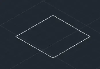
- Command: L LINE
- Specify first point.
- Specify next point or [Undo]: 3¹
- Specify next point or [Undo]: 3¹
- Specify next point or [Close/Undo]: 3¹
- Specify next point or [Close/Undo]: c
- Command: JJOIN
- Select source object or multiple objects to join at once: Specify opposite comer: 4 found
- Select objects to join:
- 4 objects converted to 1 polyline
- Command: PRESSPULL
- Select object or bounded area:
- Specify extrusion height or [Multiple]:
- Specify extrusion height or [Multiple]:6
- 1 extrusion(s) created
- Select object or bounded area:
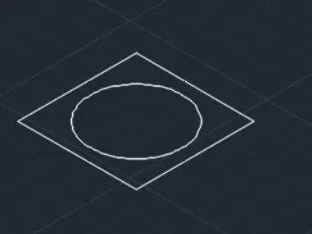
- Command: I LINE
- Specify first point:
- Specify next point or [Undo]: 1
- Specify next point or [Undo]: 1'
- Specify next point or [Close/Undo]: 1'
- Specify next point or [Close/Undo]: c
- Command: Specify opposite corner or [Fence/WPolygon/CPolygon]:
- Command: JJOIN 4 found
- 4 objects converted to 1 polyline
- Command: M MOVE 1 found
- Specify base point or [Displacement]:
- Specify second point or : 2¹
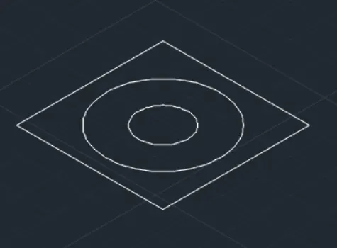
- Command: LOFT
- Current wire frame density: ISOLINES-4, Closed profiles creation mode - Solid
- Select cross sections in lofting order or [POint/Join multiple edges/MOde]: 1 found, 2 total
- Select cross sections in lofting order or [POint/Join multiple edges/MOde]:
- 2 cross sections selected
- Enter an option [Guides/Path/Cross sections only/Settings] :
- Command: m MOVE 1 found
- Specify base point or [Displacement]:
- Specify second point or :
- Command: UNI UNION
- Select objects: 1 found
- Select objects: 1 found, 2 total
- Select objects:
RESULT:
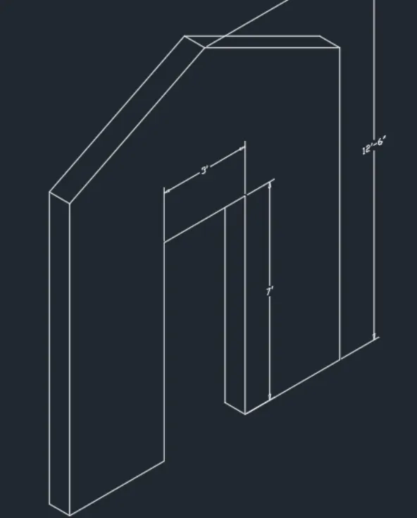
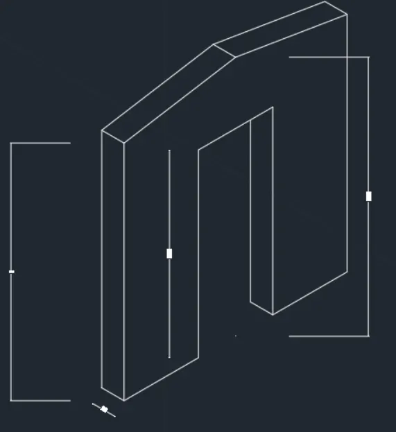
Q5. Create the 3d model of a wall as shown in Figure. Consider wall thickness as 9”.
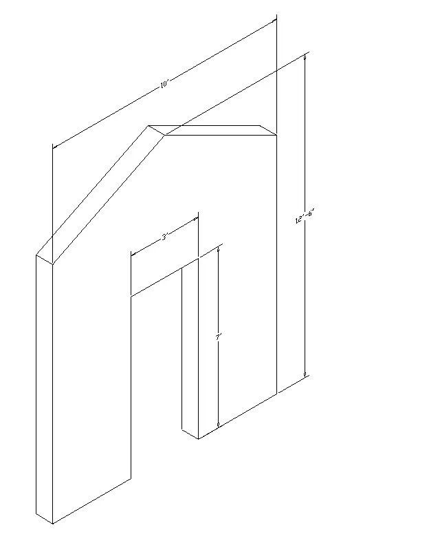
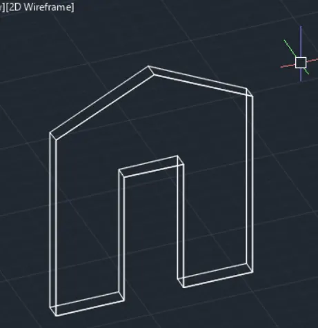
AIM: TO DRAW THE 3D WIREFRAME MODEL OF A WALL AS SHOWN FIGURE BY USING AUTOCAD TOOL
INTRODUCTION:
- THE 3D MODEL GIVEN IS A WALL DOOR OPENING.
- THE 3D VIEW OF A WALL IS SHOWN ABOVE WITH A DOOR OPENING.
- THE THICKNESS OF THE WALL IS 9" WHICH IS STANDARD THICHNESS OF OUTER WALLS OF A HOUSE.
- THE DIMENSION OF THE DOOR OPENING IS 3' X 7!
- THE TOP OF THE WALL IS GABLE SHAPE AND IS ALSO KNOWN AS GABLE WALL.
PROCEDURE:
Turn on any time ORTHOMODE
Press F5 to change the direction of the isomtric view to isoplane right or change direction in status bar to isoplane right
LINE Command: L Enter
Specify first point: mouse click
Specify next point or [Undo]: 3 Enter
Specify next point or [eXit/Undo]: <Isoplane Top> 3 Enter
Specify next point or [Close/eXit/Undo]: <Isoplane Right> 3 Enter
Specify next point or [Close/eXit/Undo]: 1 Enter
Specify next point or [Close/eXit/Undo]: 2.42 Enter
Specify next point or [Close/eXit/Undo]: 1 Enter
Specify next point or [Close/eXit/Undo]: 2.42 Enter
Specify next point or [Close/eXit/Undo]: C Enter
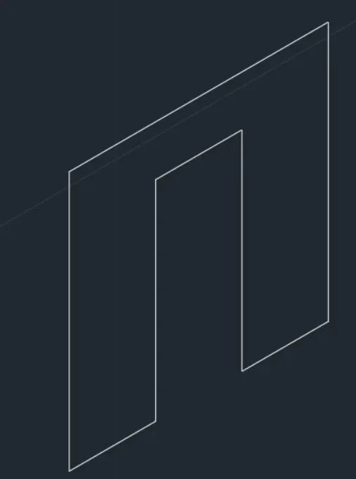
LINE Command: L Enter
Specify first point: mouse click
Specify next point or [Undo]: 0.25 Enter
Specify next point or [eXit/Undo]: mouse click
Specify next point or [Close/eXit/Undo]: Esc/Enter
LINE Command: L Enter
Specify first point: mouse click
Specify next point or [Undo]: mouse click
Specify next point or [eXit/Undo]: Esc / Enter
Command: Specify opposite corner or [Fence/WPolygon/CPolygon]:
Command: erase 2 found
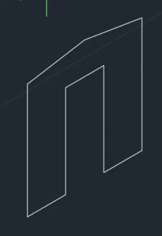
LINE Command: L Enter
Specify first point:
Specify next point or [Undo]: <Isoplane Left> 0.3
Specify next point or [eXit/Undo]: 3
Specify next point or [Close/eXit/Undo]:
Specify next point or [Close/eXit/Undo]: Esc/Enter
COPY Command: CO Enter 2 found
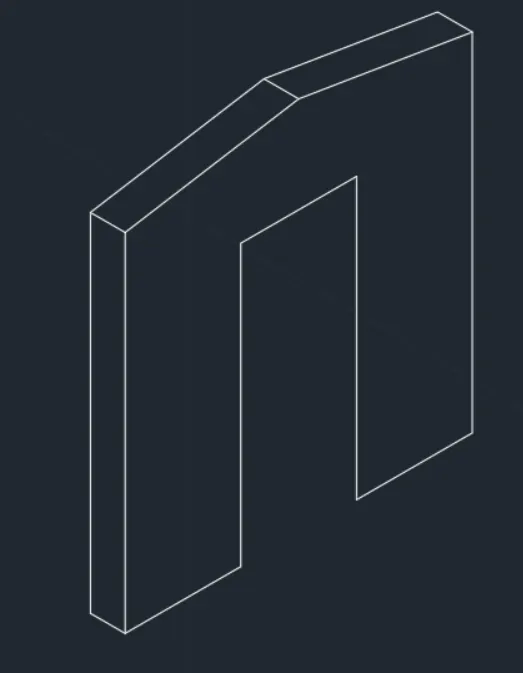
Current settings: Copy mode = Multiple
Specify base point or [Displacement/mOde] <Displacement>:
Specify second point or [Array] <use first point as displacement>:
Specify second point or [Array/Exit/Undo] <Exit: Esc/Enter
LINE Command: L Enter
Specify first point:
Specify next point or [Undo]:
Specify next point or [eXit/Undo]:
LINE Command: L Enter
Specify first point:
Specify next point or [Undo]:
Specify next point or [eXit/Undo]: Esc / Enter
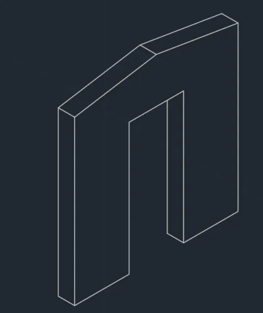
LINE Command: L Enter
Specify first point: mouse click
Specify next point or [Undo]: 0.3 Enter
Specify next point or [eXit/Undo]: mouse click Specify next point or [Close/eXit/Undo]: Esc/Enter
RESULT: