Creating various 3D Models like Furniture, Footing, Girder, Column drop with panel and Gable Wall in AutoCad
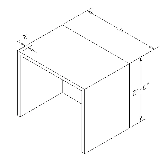
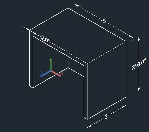
1.Create a 3D Furniture element as shown in the Figure. Assume dimensions which are missing.
Aim:
Create a 3D Furniture element as shown in the Figure in AutoCAD.
Introduction:
Create a 3D Furniture element as shown in the Figure. Assume dimensions which are missing.
Procedure:
- Open AutoCAD and open new page
- Type Unit command and set engineering and precision 0"0.0" and units to inches
- Type d (dimension style manager) command and set the engineering and precision as 0"0.0"
- Now, with the help of workspace switch from 2D to 3D modelling
- Give Command rec and set dimension 3' and 2' as shown in the questions figure
- Now type extrude command and give the height 2'6"
- Now define the new user coordinate system over the face as shown in the questions figure
- Now, again give rec command and enter dimension as 32" and 28"
- Move it by 2"
- Again, type extrude rectangle (32"X28") and give 22"
- Now, give Subtract command and select the outer extruded rectangle and hit enter inner extruded rectangle and press enter
- Tyoe shademode command and select hidden option
- Press enter
- Now, using dimaligned provided dimension
Result:
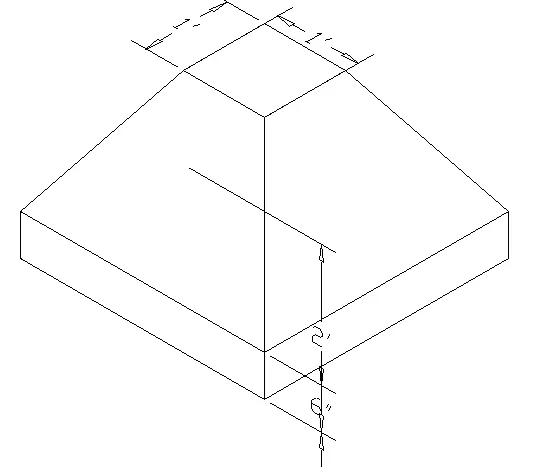
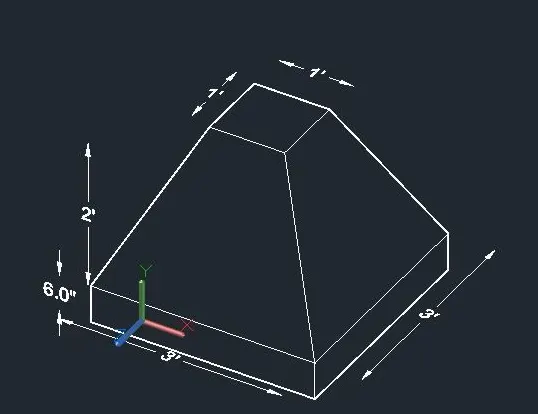
2. Create the 3d Model of an Isolated footing as shown in Figure.
Aim:
Create the 3d Model of an Isolated footing as shown in Figure in AutoCAD.
Introduction:
Create the 3d Model of an Isolated footing as shown in Figure. Assume dimensions which are missing.
Procedure:
- Open AutoCAD and open new page
- Type Unit command and set engineering and precision 0"0.0" and units to inches
- Type d (dimension style manager) command and set the engineering and precision as 0"0.0"
- Now, with the help of workspace switch from 2D to 3D modelling
- Now, command pyramid and set side and 1.5' from center and press enter
- Give circle command, and give top radius 5' and press enter
- Give the height 2' and press enter
- Now, by using presspull command, extrude its bottom by 6" as given in question figure
- Type shademode command and select hidden option
- Press enter
Result:
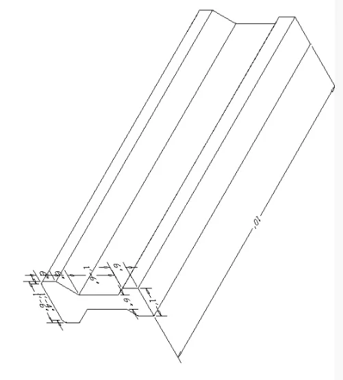
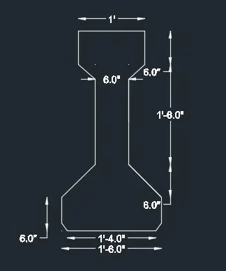
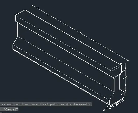
3.Create the 3D view of the AASTHO Type Girder.
Aim:
Create the the 3D view of the AASTHO Type Girder as shown in Figure in AutoCAD.
Introduction:
Create the 3D view of the AASTHO Type Girder. as shown in Figure. Assume dimensions which are missing.
Procedure:
- Open AutoCAD and open new page
- Type Unit command and set engineering and precision 0"0.0" and units to inches
- Type d (dimension style manager) command and set the engineering and precision as 0"0.0"
- Now, with the help of workspace switch from 2D to 3D modelling
- Now, command plan and twice press enter
- Draw the drawing with offset, line and dimension command
- Select the line and join all the line by join command
- Now, set the drawing to Isometric view
- Now, give command rotate 3D and select the object
- Rotate the object at x axis at an angle of 90 degree
- Now, give extrude command, select the object and extrude it by 10'
- Press enter
Result:
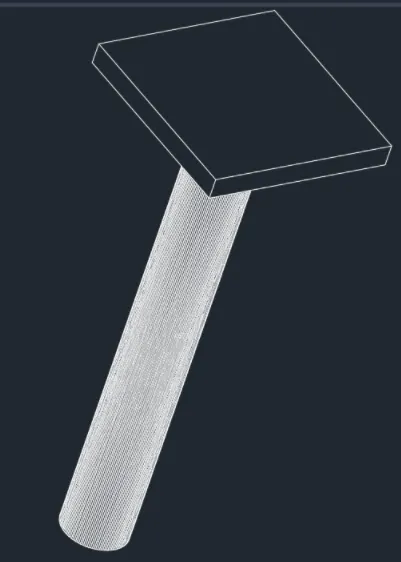
4. Create a 3d Model of a drop column with panel as shown in section and isometric view.
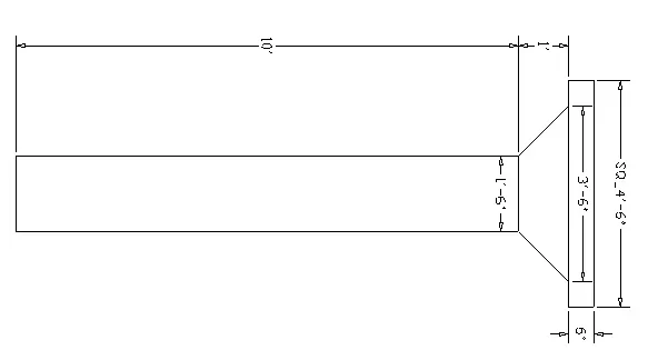
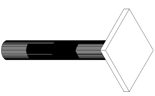
Aim:
Create a 3d Model of a drop column with panel as shown in section and isometric view as in Figure in AutoCAD.
Introduction:
Create a 3d Model of a drop column with panel as shown in section and isometric view as in Figure in AutoCAD.
Procedure:
- Open AutoCAD and open new page
- Type Unit command and set engineering and precision 0"0.0" and units to inches
- Type d (dimension style manager) command and set the engineering and precision as 0"0.0"
- Now, with the help of workspace switch from 2D to 3D modelling
- Enter Un (units) command in the command box
- Extrude the circle by using the extrude command in the ribbon 10' long
- Type command cone and draw the cone of 3'6" and bottom side of 1'6" with the height of 1'
- Now, draw rectangle by giving rec command of 4'6" and extrude it with the thickness of 6"
- Now, give command rotate 3D and select the object
- Rotate the object at x axis at an angle of 90 degree
- Use 3D orbit command to align the figure
- Press enter
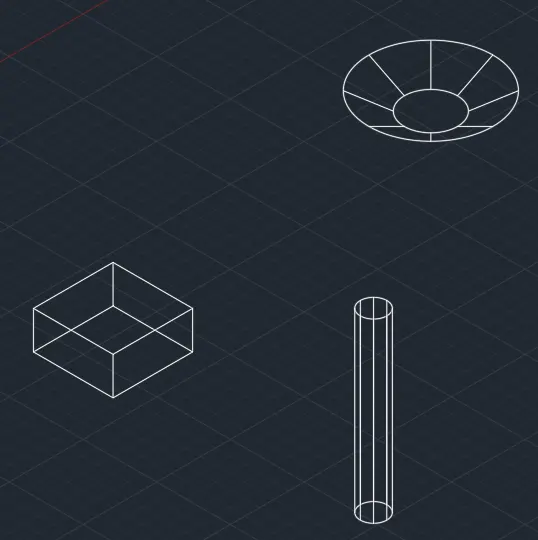
Result:
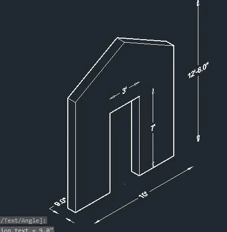
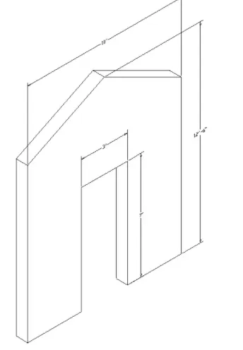
5. Create the 3d model of a wall as shown in Figure. Consider wall thickness as 9”.
Aim:
Create the 3d model of a wall as shown in Figure. Consider wall thickness as 9” as in Figure in AutoCAD.
Introduction:
Create the 3d model of a wall as shown in Figure. Consider wall thickness as 9” as in Figure in AutoCAD.
Procedure:
- Open AutoCAD and open new page
- Type Unit command and set engineering and precision 0"0.0" and units to inches
- Type d (dimension style manager) command and set the engineering and precision as 0"0.0"
- Now, with the help of workspace switch from 2D to 3D modelling
- Now, command plan and twice press enter
- Draw the drawing with offset, line and dimension command
- Now, set the drawing to Isometric view
- Now, give command rotate 3D and select the object
- Rotate the object at x axis at an angle of 90 degree
- Extrude command and select the object and extrude by 9'
- Now, select rectangle by giving rec command of 3'X7' and extrude by 9"
- Type subtract command and first select outer and press enter, then select inner one nd press enter
- Type shademode command and select hidden option
- Press enter
Result: