Creating various 3D Models like Furniture, Footing, Girder, Column drop with panel and Gable Wall in AutoCad
ASSIGNMENT 12
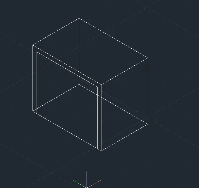
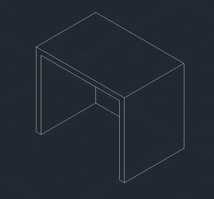
- create a 3D Furniture element using AutoCAD software.
Ans -
Various commands used:
- QNEW command
- UN command
- Box command
- Rectangle common d
- Extrude command
- SUBTRCT command
- DIMLIN command
- 3DF command
- UCS command
Procedure:
- Type QNEW in command box, press enter, select the imperial as default setting and select
- Type UN in command box, press enter, select the measuring unit engineering with the precision 0’—0".
- From setting of status bar change setting from strolling and annotation to the 3D
- Type LIMAX in common I box, press enter, specify max limit as 20",20' and press
- Type Z in command box, press enter, type A in command box and press enter.
- From view tab keep on the view cube icon from the
- Select home icon of view cube to set the default position of UCS
- Type BOX in command box, press enter.
Specify first corner point,select the length option from command box Press enter, specify length as 3' and Press enter.
- Specify width as 2'4-, press enter and specify height as 26" and press
- Type UCS in command box, press enter, select the face option from command box, and select the face on which we want the UCS icon such that XY plane.
Select dimension option from command box, specify length as 28", width as 2'4", press enter and draw the rectangle.
- TYPE MOVE in command box, press enter, select the base point as corner point of rectangle and specify second point as 2”< 180 and press
- Type EXTRUDE in command box, press enter, select the just Drawn rectangle on d specify extrude height as 0,O,—2’2" on I P +
- type SUB in command box, press enter, select the external Press enter, select internal extruded rectangle
and press enter.
” TYP UCS in command box, press enter.
- Select the face option from command box, and select the top face such that XY plane lie on the top face of the box.
- TYP Dlk4LlN in command box, press enter and give the dimensions
- From the viewport control change the custom visual style from 2D wireframe to HIDDEN to get the desired
- Type 3DF in command box, press enter and adjust the view as per requirement
Result
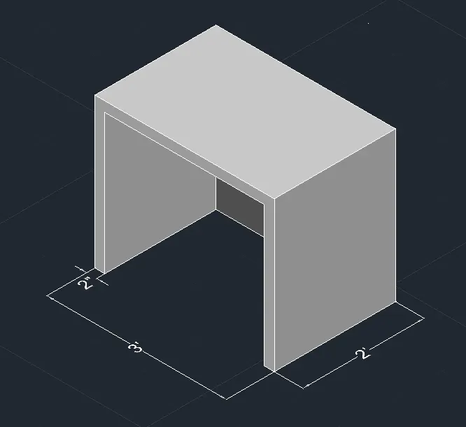
- create the 3D model of on isolated footing using AutoCAD software.
Ans -
Various commands used
- QNEW command
- UN command
- BOX command
- DIMLIN command
- UCS command
- 3DP command
- Type QNEW in command box, press enter, select the imperial as default setting and select
- Type UN in command box, press enter, select the measuring unit engineering with the precision 0'—0".
- Type LIMAX in command box, press enter, specify max limit as 20'10’ and press enter.
- Type Z in command box, press enter, type A in command box and press enter.
- From view tab keep on the view cube icon from the
- Select home icon of view cube to set the default position of ucs
- Type BOX in command box, press
- Specify first corner point, select the length option from command box, press enter, specify length as 4' and
- Specify width as 4', press enter and specify height as 6" and press
Type pyramid in command box, press enter, select the edge option from command box, select the first end point of edge as corner of top of box, and second endpoint of edge as adjacent corner
- Select the top radius option from command box, specify top radius as 6", press enter and apply height as 2' and press
- Type UCS in command box, press enter.
- Select the face option from command box, and select the top face such that XY plane lie on the top face of the box.
- Type DIMLIN in command box, press enter and give the
- From the viewport control change the custom visual style from 2D wire frame to HIDDEN to get the expected view.
- Type 3DP in command box, press enter eng adjust the view as per
Result
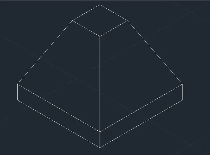
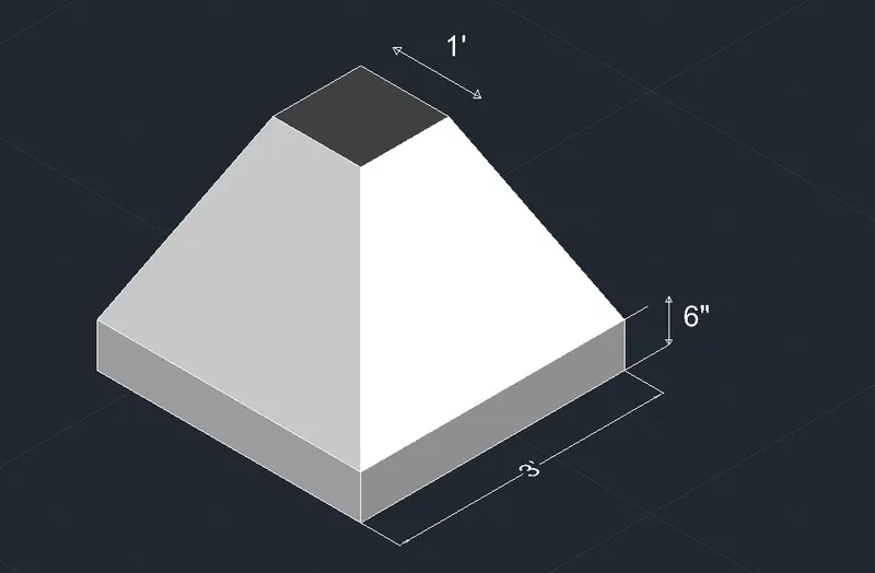
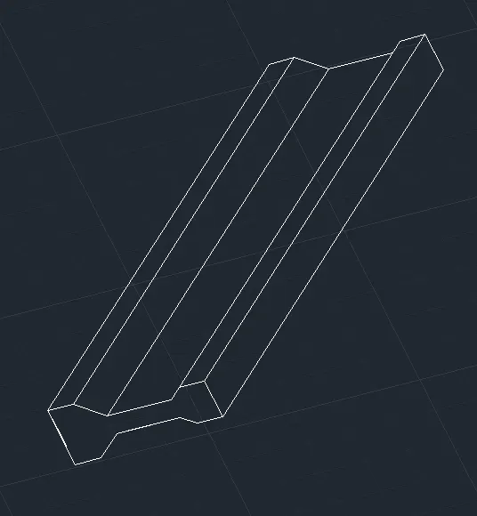
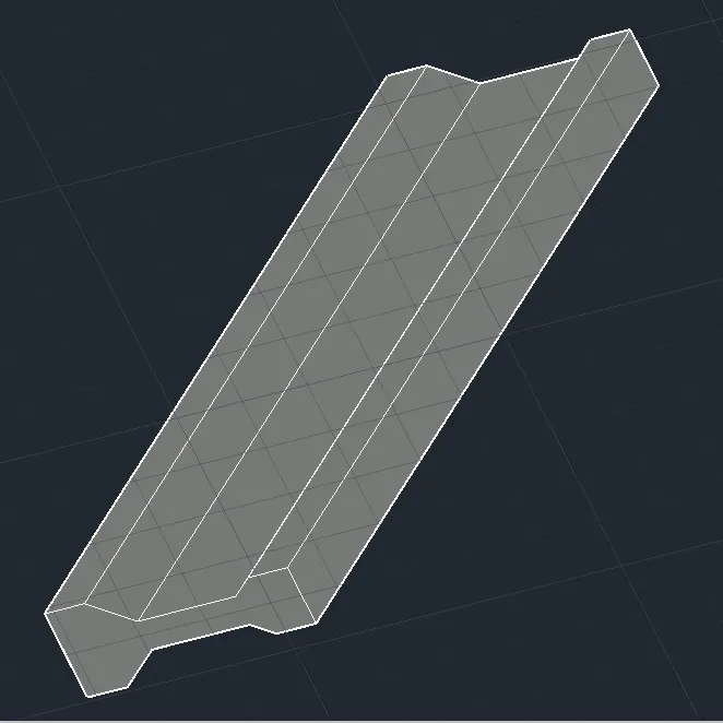
- Create the 3D view of the AASTHO Type Girder
using AutoCAD software.
Ans -
Various commands used
- QNFW command
- UN command
- 3DF command
- MIR command
- Join command
- Line command
- SWEEP command
- UCS command
- DIMLIN command
- DIMCON command
- Type QNEW in command box, press enter, select the imperial as default setting and select
• Type UN in command box, press enter, select the measuring unit engineering with the precision 0’-0”.
- From setting of status bar change setting from drafting and annotation to the 3D
- Type LIMAX in command box, press enter, specify max limit as 20"J0' and press
• Type Z in command box, press enter, type A In command box and press enter.
- Select the Cop view from viewport
- Type 3P in command box, press enter and specify first point on the
• Specify next point as @9",0 and press enter.
Specify next point as @0,6" and press enter.
- Specify next point as @-6",6- and press
- Specify next point as @ 0,1"—6" and press
- Specify next point as @3-,3" and press
- Specify next point as @0,6" and press enter.
- And specify next point as @-6-,O and press enter.
- Type MIR in command box, select the entire lines, specify first point on mirror line as first end point and second point on mirror line as second end point on the poly line and mirror it.
- geometry to create it as single object
- Change the view to custom view from view box
- Type L in command box, press
- Select the first point and specify next point as @0- -10’, press enter and press escape.
- Type Sweep in command box, press enter, select the drown object, press enter, select the path to sweep as drawn line of 10”
- Select the face option from command box, select the face on which dimensions ore required and press
- Type DIMLIN in command box, press enter and give the
- From the viewport control change the custom visual style from 2D wireframe to HIDDEN to get the desired
Result
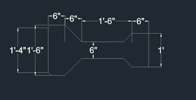
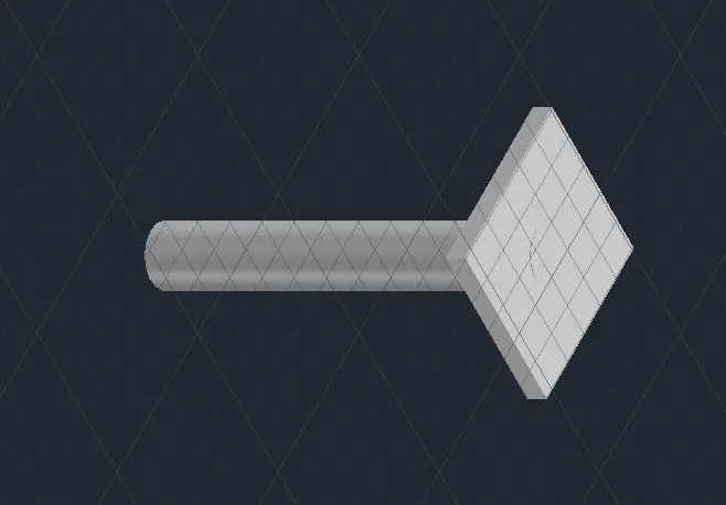
- create a 3d Model of a drop column with panel using AutoCAD software.
Ans -
Introduction:
Various commands used
- QNEW command
- UN command
- Box command
- Pyramid command
- Cylinder command
- Hide command
- FACETRES command
- REG command
* TO CONF\TO OF d
- MOVE command
- DlM LINE command
Procedure:
Type QNEW in command box, press enter, select the imperial as default setting and select ok.
- Type UN in command box, press enter, select the measuring unit engineering with the precision 0'—0”. From setting of status bar change setting from drafting and annotation to the 3D
Type LIMAX in command box, press enter, specify max limit as 20’,20' and press enter. Type Z in command box, press enter, type A in command box and press enter.
• From view tab keep on the view' cube icon from the ribbon.
- Select home icon of view cube to set the default position of UCS
- Type BOX in command box, press enter,
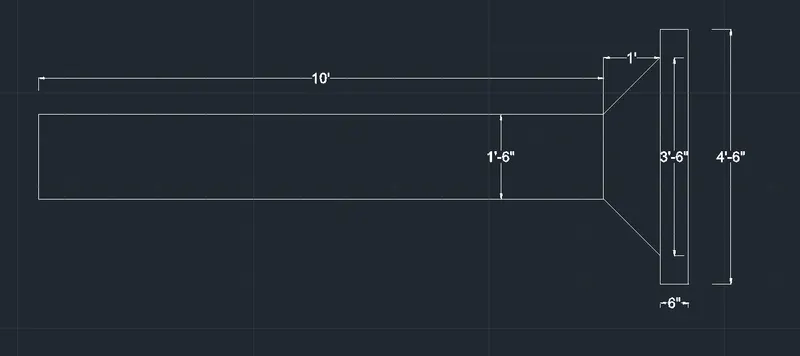
- Specify the first corner point select the length option from the command box, specify length as 4'6, press enter, specify width as 4’6, press enter, specify height as 6" and press
- Type REC in command box, press enter, select the dimension option from command box, specify length as 3’6", width as 3’6” and press
- Type MOVE in command box, press enter, select the base point as corner of rectangle, specify next paint as @6“,6” and press
- Type PYRAMID in command box, press enter, select the Edge option from command box, select first endpoint of edge as corner of rectangle, second endpoint of edge as adjacent corner of rectangle, select the TOP radius option from command box, specify top radius as 1'6“, press enter, specify height as 1‘ and press enter.
- Type CYLINDER in command box, press enter, select the 3P option from command box, select the first second and third point as midpoints of top of pyramid, specify height as 10’ and press
- Type FACETRES in command box, press enter, specify new value as 10 and press
- Type REG in command box, press enter, select the object and press
- Change the view to front from viewport
- Type RO in command box, press enter, select the base point as right midpoint of box, specify rotation angle as 90 and press
- From viewport control change the custom view to hidden to get the
- Type DIMLIN in command box, press enter and give the
From the viewport control change the custom visual style
from 2D wireframe to HIDDEN to get the desired view
result -
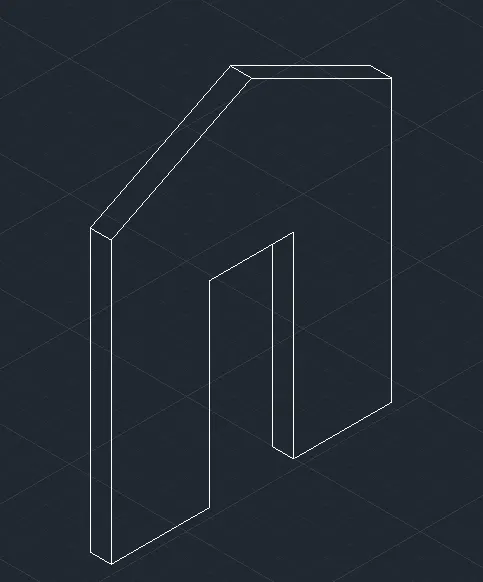
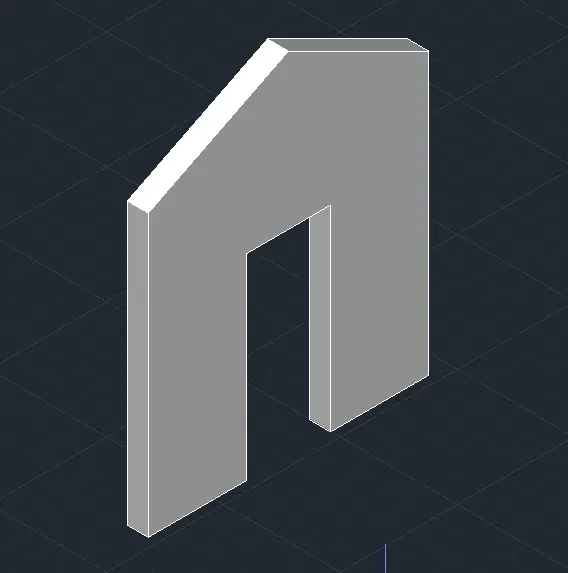
5.Create the 3d model of a wall using AutoCAD software.
Ans -
Various commands used
- QNEW command
- UN command
- LIMAX command
- Zoom command
- 3P command
- MIR command
- Region command
- Extrude command
- DIMLIN command
- Type QNEW in command box, press enter, select the imperial as default setting and select
" TYPE UN in command box, press enter, select the measuring unit
engineering with the precision 0'—0".
- From setting of status bar change setting from drafting and annotation
To the 3D modeling.
- Type LIMAX in command box, press enter, specify max limit as 20',20“ and press enter.
- Type Z in command box, press enter, type A in command box and press
- From view tab keep on the view cube icon from the
- Select home icon of view cube to set the default position of ucs icon.
- Type UCS in command box, press enter, select the X option from command box, specify rotation angle as 90 and press enter.
- Type 3P in command box, press enter, specify first point on the
- Specify next point as @—5',—2'6-' and press
- Specify next point as @42",0 and press
- Specify next point as @0,7' and press
- Specify next point as @0,18- and press
- Type MIR in command box, press enter, select the entire drawing, select the first point on mirror line as 6tort point of poly line and specify second point on mirror line as other endpoint of poly line and mirror the poly line.
- Type REGION in command box, press enter, select the entire object by using the crossing
- Type EXTRUDE in command box, press enter, select the object and specify height as @0—9” and press
- Type DIMLIN in command box, press enter and give the
- From the viewport control change the custom visual style from 2D wire frame to HIDDEN to get the respective view
Result -