Creating various 3D Models like Furniture, Footing, Girder, Column drop with panel and Gable Wall in AutoCad
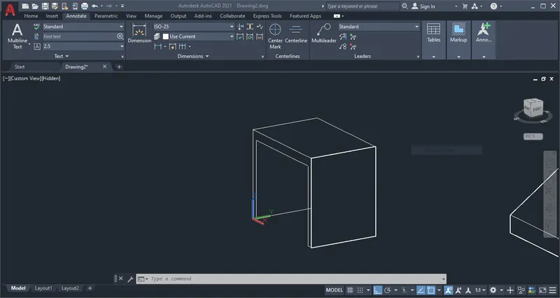
AIM: Creating a 3D furniture element as shown in figure.
PROCEDURE:
- Click 3Dmodelling view inn settings at the bottom right corner.
- Locatae a starting point let say (0,0,0) then use coordinate system to draw the object.
- Locate the second point as follows (o,3',0);
- 3rd point (3',0,0);4th (0,-3',0). simillarly continue this and draw the object.
- Click 3DFace command and draw 4 corners and join.
- Use hide option to hide the drawing line.
- We can also use shaded option to shade the object.
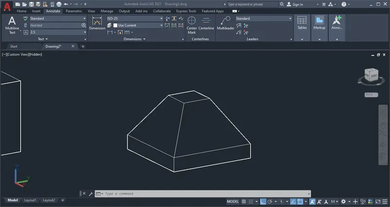
AIM: Create a 3D model of an isolated footing with 3D modelling.
PROCEDURE:
- First use PLAN command to go to plan view.
- use REC to create outer rectangle as per given dimensions.
- Take offset(O) for inner rectangle.
- Go to 3D view by clicking VIEW CUBE.
- Select the innner rectangle and move it in Z -axis as per dimensions. or use coordinate system (0,0,2').
- Now connect the edges as shown in fig by line command.
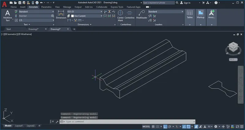
AIM: To Create the 3D view of the AASTHO Type Girder.
PROCEDURE:
- Use plan command and draw the fig as shown below
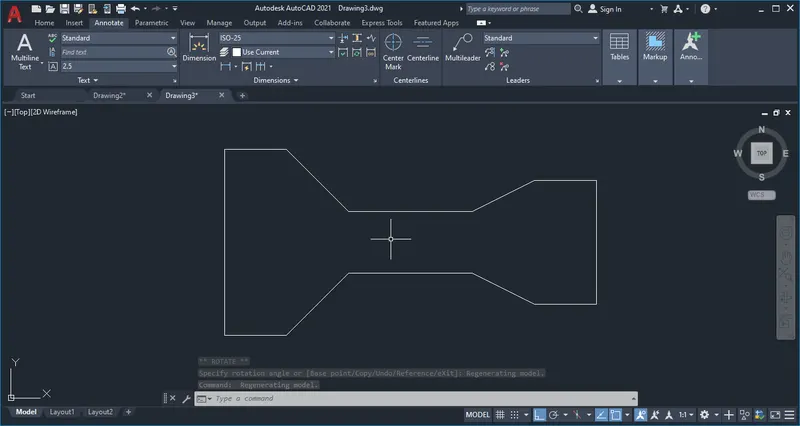
- Then go to 3D view by using VIEW CUBE.
- Use 3Drotate command to rotate object along Z-axis.
- Use line command extend it in Y-axis by 10'.
- Join all the lines at the other corner as shown below.
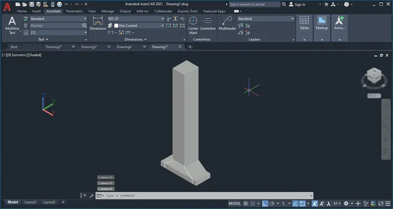
AIM:To Create a 3d Model of a drop column with panel as shown in section and isometric view.
PROCEDURE:
- Use plan command and draw the fig as shown below
- Then go to 3D view by using VIEW CUBE.
- Use 3Drotate command to rotate object along Z-axis..
- USE REG command and EXT command to extrude the object.
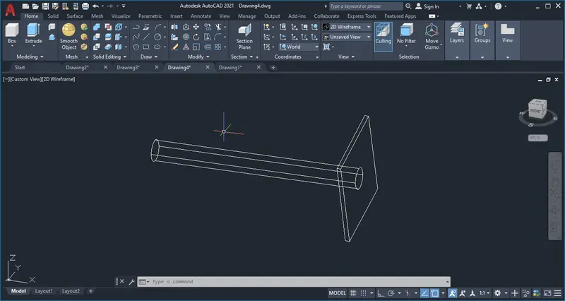
Use REC to create rectangle and Rotate it to a desire angle by 3D rotate commmand.
Draw a line from centre of rectangle towards negative X-axis.
create circle(C) and use SWEEP option to create circular column as shown below.
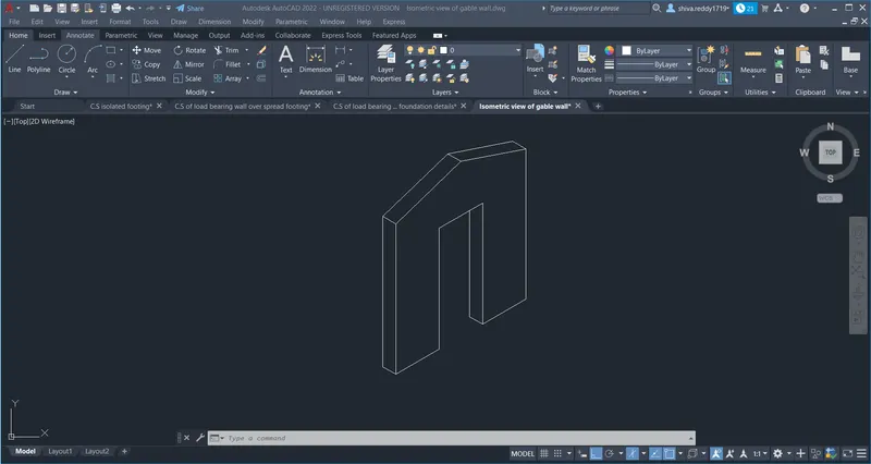
AIM: To Create the 3d model of a wall as shown in Figure. Consider wall thickness as 9".
PROCEDURE:
- Click isometric drafting to create isometric view.
- Draw lines as per dimensions given.
- Use isometric left, isometric right, isometric top to draw the object.