Creating Levels, Grids, Layout and model elements for a residential unit using REVIT
Challenge -2
1) What is BIM? Summarize the features of BIM and benefits of using BIM over 2D CAD tools.
BIM: BUILDING INFORMATION MODELLING
- In Revit BIM is rather than a software it is process.
- Mainly BIM is divided into two core concepts they are: A. Coordination B. Computation
- Using Autodesk Revit, we can get coordination with multiple disciplines
- If we think Revit as a BIM tool it will perform computations such as material schedule, quality schedule, how to perform energy evaluation or analysis or different tolls associated with Revit.
- Autodesk Revit is used to activate the coordination and computation as a part of our project and modelling purpose.
LEVELS IN BIM
Different levels of BIM can be achieved for various types of projects. Each level represents a different set of criteria that demonstrates a particular level of ‘maturity.’ BIM levels start with 0 and go to 4D, 5D, and even 6D BIM. The purpose of these levels is to gauge how effectively, or how much information is being shared and managed throughout the entire process.
- Level 0 BIM: Paper-based drawings + zero collaboration
- Level 1 BIM: 2D construction drawings + some 3D modeling
- Level 2 BIM: Teams work in their own 3D models
- Level 3 BIM: Teams work with a shared 3D model
- Levels 4, 5, and 6 BIM: Adding in scheduling, cost, & sustainability information
DIFFERENCE BETWEEN 2D CAD AND BIM
Basically, when using CAD for building design, you focus on creating drawings. When using BIM, you focus on creating a building model, and then the drawing scan be generated from the model. This saves time because you really do not have to draw anything twice. With CAD, you typically draw floor plans and then sections. But with BIM, you create the elements in one view, and they appear in all views in which their visibility is turned on.
Additionally, when it comes to documenting your design with tags and schedules, the parameters that are programmed into the elements can easily be used. This saves time when it comes to updating building components, and it cuts down on errors since a component will not be tagged differently in two views
KEY BENEFITS
- Establish the best solution quickly
- Manage changes easily
- Achieve faster design times.
- Maximize profitability and efficiency
2) Understand the concept of Categories, Families, Elements, Instances in Revit. Go to Insert Tab, choose a category. Pick a family and element. Understand the instances and insert it to Revit model
Aim:
To Understand the concept of Categories, Families, Elements, Instances in Revit.
Category:
A Category controls the organization, visibility, graphical representations, and scheduling options of Families within the Project.
Family:
A Family is a grouping of 2D and/or 3D information that serves to represent a discrete building or documentation element in the Project. It defines parametric, graphical, and documentation requirements.There are three kinds of Revit Families
System:
These are the families that are pre-defined families specific to a Revit Project. Their parametric, graphical, and documentation requirements already exist. They cannot be created in, deleted from, loaded into, or saved out of the current project.
Loadable:
These are the families that are user-defined families built in an editing mode called the Family Editor using family templates. Their parametric, graphical, and documentation requirements can be defined from scratch. They can be created and loaded into a project as well as, deleted or saved from a project.
In-place:
These are the families that are user-defined families created to represent a one-of-a-kind element unique to the project. Like System families they cannot be loaded into or saved out of a project but, they can be created within the context of the project using familiar Family Editor tools.
Type:
A Type is a specific representation in a Family defined by distinct parametric, graphical, and documentation characteristics which makes it unique from other Types in the Family.
Instance:
An Instance is an individual representation of a Type in the Project defined by unique parametric, graphical, and documentation characteristics which makes it unique from other Instances in the Project.
Procedure:
- Go to Insert Tab as shown below and click on “Load Family”
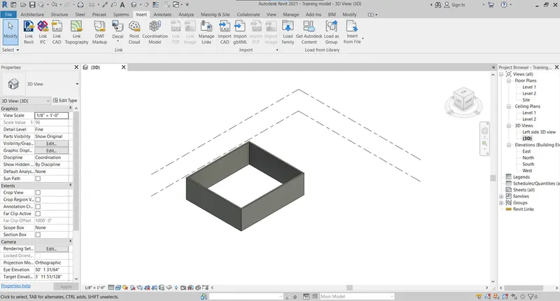
- From the pop-up box select libraries
- Select English / Door / Custom Door as shown in the figure below
- Click on door and click OK
- Families can also be added from the project browser as follows
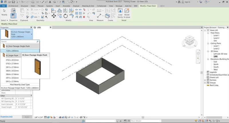
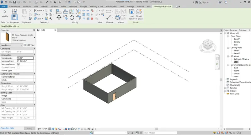
Result:
we understood the concept of Categories, Families, Elements, Instances in Revit.
3) Setting up a Project – Open a project file with architectural template. Save the file with appropriate name. Set up the project units to Imperial / Metric based on your convenience of modelling. Complete the project information under Manage tab. Set up the maximum backups for project file to 3
Aim:
To Set up a project
Procedure:
- on the main page of the Revit software, we have to click on the new option in that we have to select imperial architectural template and project in down options.
- And after creating a project. we have to go the manage toolbar and there we will find the project information option and on clicking on that we can save every information about the project.
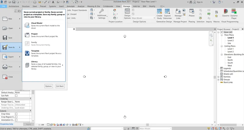
- Go to the Manage tab
- Click on “Project Units”
- A dialogue box of project units opens
- Units are changed accordingly
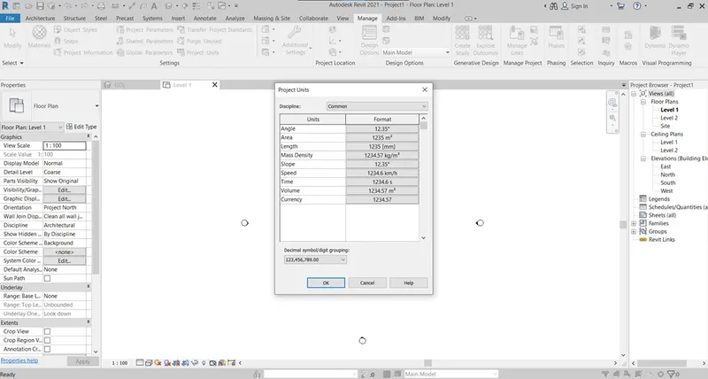
Result:
I understood the procedures to save the file, write the project information, and setting the maximum backup for a project.
4) Understand the concept of Levels and Grids. Follow the naming and conventions. Create the following Levels: (Convert to metric equivalents if metric is your units)
Ground Floor @ 0’
First Floor @ 10’
Second Floor @ 20’
Roof @ 30’
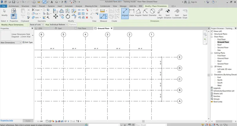
Grids Transverse Grids A, B, C, D, E @ 10’ spacing
Longitudinal Grids from 1 to 10 @ 20’ spacing
Aim:
To create levels and grids for standard layout
Procedure:
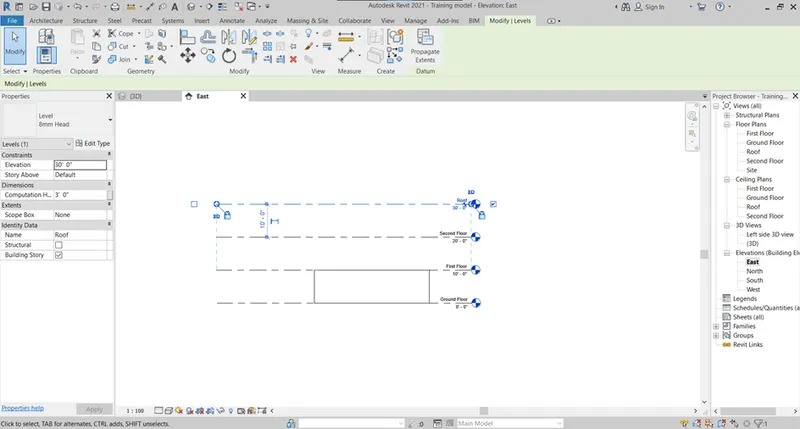
- Create the following Levels:
Ground Floor @ 0’
First Floor @ 10’
Second Floor @ 20’
Roof @ 30’
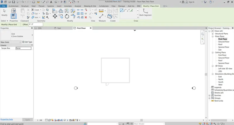
- Create the following Grids:
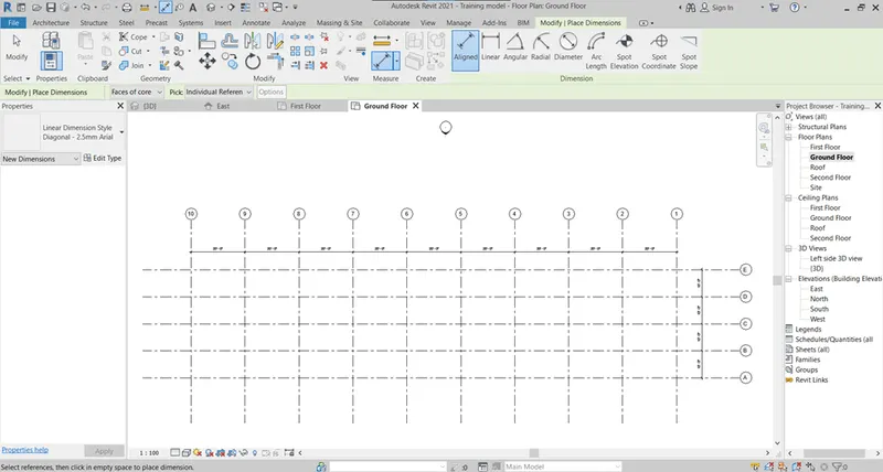
Grids Transverse Grids A, B, C, D, E @ 10’ spacing
Longitudinal Grids from 1 to 10 @ 20’ spacing
Result:
The Levels and grids are created as required.
5) 3D modelling of residential unit – From looking at your house / or a place you aspire. Create a conceptual layout of the residential unit. You can measure using a tape or
you can access your residential plan to create a similar layout.
Aim:
To create 3D modeling of the residential unit
Procedure:
- Create a new project.
- In the toolbar select architecture.
- select the required wall.
- Using the wall select the line command
- create a layout of our inspiration.
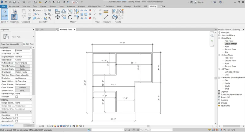
- In the toolbar menu we have annotate option in that we have to select the align option to give the dimensions or measurement to the layout.
- After clicking on that to start giving dimensions we have to select the left end of the layout and then drag it to the right end.
- similarly select the align option and select the top end of the layout and drag it to the bottom end and then drag it outwards from the layout to represent it.
Result:
This will be the final 3D vision of our layout with dimensions.
6) In the layout created draft the level of details you are planning to include – Dimensions of room, components you plan to add in the residential unit.
Aim:
To draft the level of details you are planning and to include – Dimensions of room, components you plan to add in the residential unit.
Procedure:
- create a layout with rooms.
- For the created layout along with the rooms inbuilt in it. firstly, we have to select elevation view in it and set all elevations (Ex. east, west, north, south) properly by selecting a wall which is not in
- Same elevation and dragging it tother enquired elevation in or to get an exact model
- Dimensions of respective are also shown in the figure
Result:
The levels and dimensions for the created layout has been assigned successfully.
7) Identify the residential model elements such as Door, Windows, Tables, Chair, Couch, Bed, Lamps from the library and insert them to the model. Save the project for use for Assignment 3
Aim:
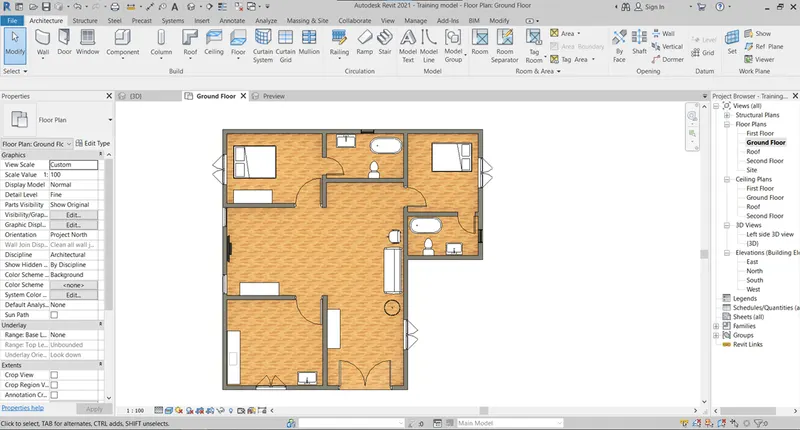
To Identify the residential model elements such as Door, Windows, Tables, Chair, Couch, Bed, Lamps from the library and insert them to the model.
Procedure:
- Create A new project as per our convenience.
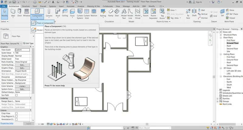
- go to the Insert tool bar and select load families
- And then after clicking on load families we can select any category and elements which we need to insert in our project .
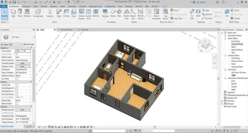
Result:
The final view will represnt the project with Doors, Windows, Tables, Chair, Couch, Beds, Lamps