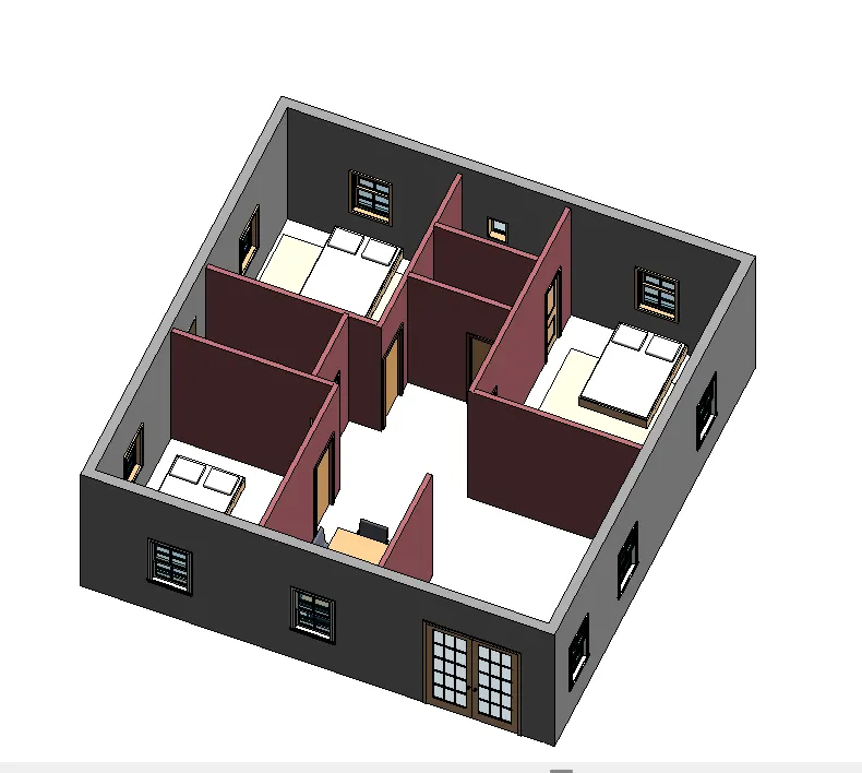
Creating Levels, Grids, Layout and model elements for a residential unit using REVIT
Ans-1)
AIM- To get information about BIM and benifits of using BIM over 2D CAD tools.
RESULT-
- Building Information Modeling (BIM):
- BIM is a tool for Building Information Modeling or Building Information Management.
- It is a process of creating and managing information for a built asset.
- It is used by professionals to plan, design and construct a structure or building.
- It is a highly collaborative process that allows professionals to work on the same model simultaneously i.e. that structural engineers, architects, MEP engineers, designers, project managers, and contractors can work in a more collaborative environment.
- It is like all of the information of building gathered from conception to completion.
- It can be used at all stages of a building's life- from inception to operation and even renovations and renewals.
- Features of BIM:
- Better 3D visualization of the entire project
- Easy collaboration between multiple teams and trades
- Simplified communication and understanding of design intention
- Reduced rework and revisions at every stage of the project
- More efficient site planning and scheduling
- More efficient hand-offs between steps in the construction stage
- Real-time cost visualization o Simplified cost analysis
- Reduced energy consumption in the long run
- Better operational management of the building or structure after handover
- It is a physical representation of the physical and functional characteristics of the building process, that
provides every minute detail of the project.
- Benifits of BIM over 2D CAD tools:
- CAD deals with the process of designing models and floorplans but BIM includes so much more than
designing - BIM pulls your documents into a single database.
- Resource tracking is a key component of BIM models.
- Easy collaboration between multiple teams and trades.
- Real-time cost visualization
- any changes to materials or component will automatically get updated to the corresponding schedules
and drawings. - BIM is not limited to rendering, but specifies the performance and functions of each object.
- With BIM we can do energy performance calculations.
- All views can be observed according to specific design phases.
- BIM gives us more realistic and accurate idea of the final structure.
Ans-2)
AIM- To understand the concept of categories, families, elements, instances in revit.
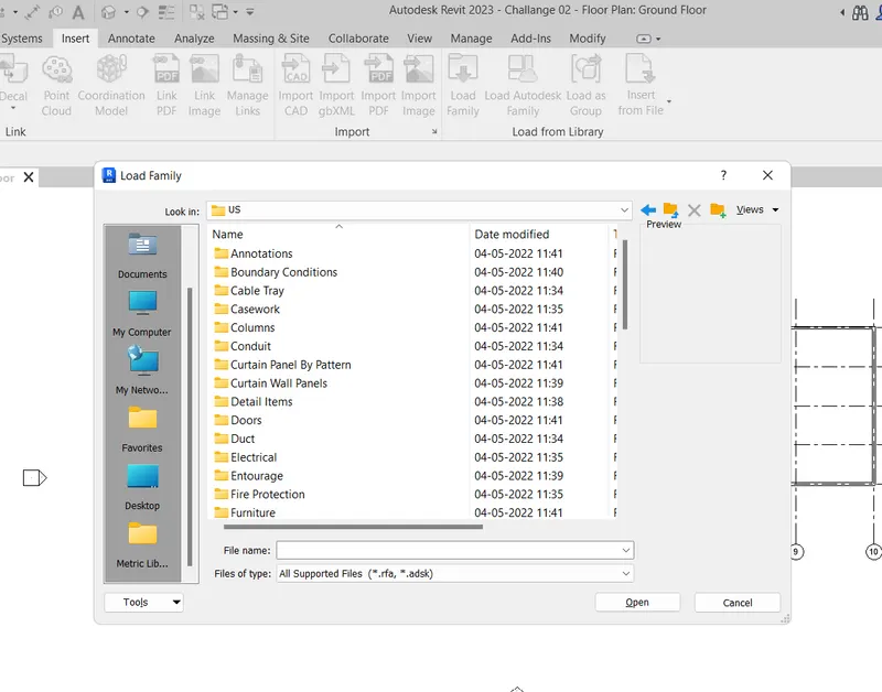
INTRODUCTION- We can select Categories, Families, Elements, Instances by selecting load family from insert toolbar.
• Categories
- Classification for families for example doors, windows, furniture elements, and so on.
- Families are grouped and sorted by categories in the content library in the project browser.
- Categories are an import tool within Revit for identifying the inferred type of an element, such as anything
in the Walls category should be considered as a wall. - The API exposes access to the built in categories within Revit via the Document.
• Families
- A family is a group of elements with a common set of properties, called parameters, and a related
graphical representation. - Different elements belonging to a family may have different values for some or all of their parameters, but the set of parameters (their names and meanings) is the same.
- All of the elements you use in Revit are families. Some families, such as walls or level datums, are included in the model environment. Other families, such as specific doors, or fixtures, need to be loaded into the model from an external library. You can't create anything in Revit without using a family.
• Elements
- Elements are the building blocks of a 3D model.
- They represent the real-world components that a designer adds to the model.
- Some elements such as walls, windows, and beams are 3D and appear in all views.
- You can think of these elements as components that exist in a building
- Other elements such as tags, dimensions, or other annotations appear only in the view in which they are
placed. For example we select the family from the door catagory, after selecting the family the new tab will visible. - Next there will be different sizes of door is there, select any one of them.
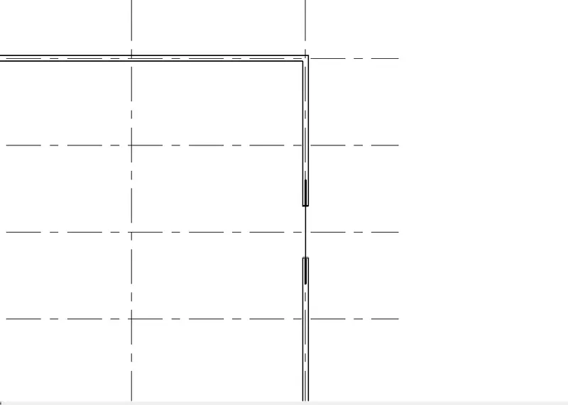
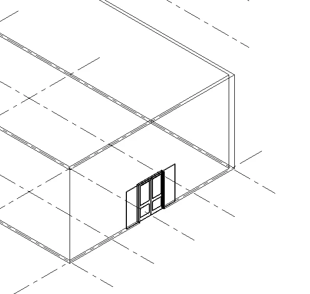
- Next that element is applied to the 3d model, and it will appears in the properties tab at the left side of the screen, as shown below.
• Instances
- Instances are individual graphical/geometric elements placed in a Revit model e.g. a single Wall, or a single Door, or any other single element.
- As a subset of Revit Elements, Instances inherit a series of Parameters from their Category and Type and might have instance parameters as well that only belongs to that single instance,
- The single element attatched to the wall is door, that door we call as instance, as shown below.
Procedure-
Step-1)
- Categories-
- Classification for families for example doors, windows, furniture elements, and so on.
- Families are grouped and sorted by categories in the content library in the project browser.
- Categories are an import tool within Revit for identifying the inferred type of an element, such as anything in the Walls category should be considered as a wall.
- The API exposes access to the built in categories within Revit via the Document.
Step-2)
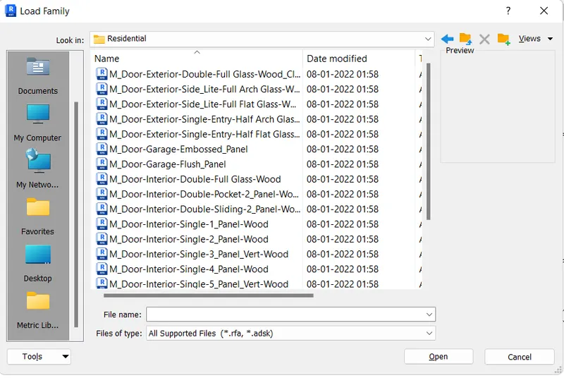
- Families
- A family is a group of elements with a common set of properties, called parameters, and a related graphical representation.
- Different elements belonging to a family may have different values for some or all of their parameters, but the set of parameters (their names and meanings) is the same.
- All of the elements you use in Revit are families. Some families, such as walls or level datums, are included in the model environment. Other families, such as specific doors, or fixtures, need to be loaded into the model from an external library. You can't create anything in Revit without using a family.
Step-3)
- Elements
- Elements are the building blocks of a 3D model.
- They represent the real-world components that a designer adds to the model.
- some elements such as walls, windows, and beams are 3D and appear in all views.
- You can think of these elements as components that exist in a building.
- Other elements such as tags, dimensions, or other annotations appear only in the view in which they are placed.
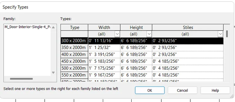
- For example we select the family from the door catagory, after selecting the family the new tab will visible.
- Next there will be different sizes of door is there, select any one of them.
- Next that element is applied to the 3d model, and it will appears in the properties tab at the left side of the screen, as shown below.
Step-4)
- Instances
- Instances are individual graphical/geometric elements placed in a Revit model e.g. a single Wall, or a
single Door, or any other single element. - As a subset of Revit Elements, Instances inherit a series of Parameters from their Category and Type and
might have instance parameters as well that only belongs to that single instance. - The single element attatched to the wall is door, that door we call as instance, as shown below.
3) Setting up a Project – Open a project file with architectural template. Save the file with appropriate name. Set up the project units to Imperial / Metric based on your convenience of modelling. Complete the project information under Manage tab. Set up the maximum backups for project file to 3.
- Ans-3)
AIM- To make set up of a project.
INTRODUCTION
- REVIT
- Autodesk Revit is a BIM software means a Building Information Modelling.
- Autodesk Revit used by civil engineers, architects, landscape architects, structural engineers MEP
engineers, designers, etc for detailed desiging and drawing. - Autodesk Revit is used for detailing of architectural drawings, structural drawings, MEP detailing drawings.
- Autodesk Revit is used for 2D as well as 3D modelling.
- It automatically updates floor plans, elevations, and sections as your model develops.
- Manage toolbar
- Manage toolbar includes material managment, additional settings, project location details, designs
options, create study, explore outcomes, manage links, phasing, inquiry, macros and visual programming, etc.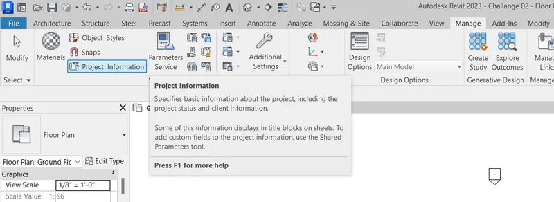
PROCEDURE
STEP1-
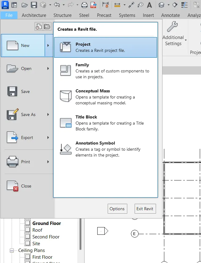
- Go top the floor plan
- click on the file
- click on New
- click on the project
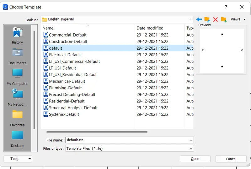
Step-2)
- Now select project and press ok
- select project as defaults
Step-3)
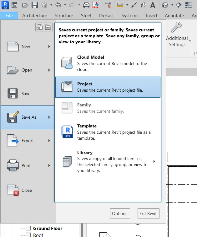
- Click on the file menu
- click on save As
- select the project
STEP-4)
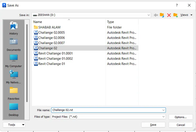
- After clicking on PROJECT select folder in which we have to save the file.
- Then name the file as STRUCTURAL PROJECT C1 then click on SAVE.
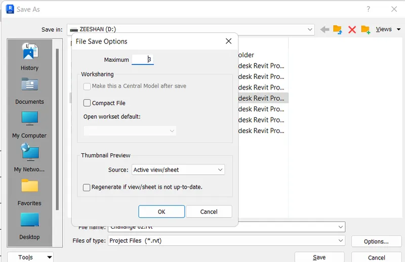
- Save project as architectural project Cl. • and put maximum backups for project file 3
STEP-5)
- Go on the Manage toolbar
- click on the project information toolbar
STEP-6)
- Enter all project information and click ok
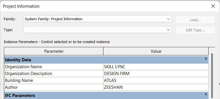
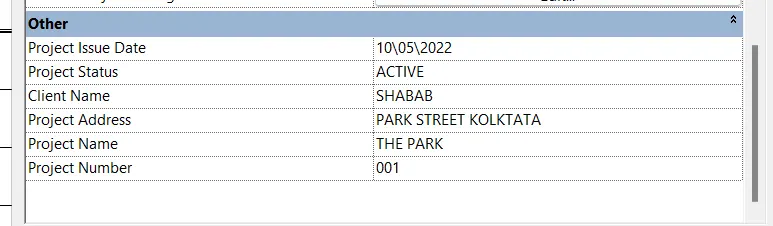
RESULT:
set up the project enter the project information and setup to the maximum no. of backup 3.
Ans-4)
AIM-To undestand the concept of level and grids.
INTRODUCTION
LEVELS
- Open the section or elevation view to add levels to.
- On the ribbon, click Level.
• Architecture tab-Datum panel-Level
• Structure tab-Datum panel- Level - Place the cursor in the drawing area and click.
- Draw level lines by moving the cursor horizontally.
- Click when the level line is the correct length.
- Note-You can change the name of the level by clicking the number to select it. You can also change the
height of the level by clicking the dimension. - Use the Project Browser to rename the level, if desired.
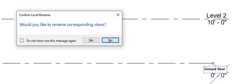
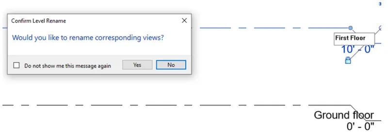
- Note- If you rename the level, you are asked if you would like to re-name corresponding plan views as
well.
GRIDS
- Use the Grid tool to place column grid lines in the building design.
- You can then add columns along the column grid lines.
- Grid lines are finite planes.
- You can drag their extents in elevation views so that they do not intersect level lines.
- This allows you to determine whether grid lines appear in each new plan view that you create for a project.
- Grids can be straight lines, arcs or multi-segmented. You can hide grid lines after you add them.
- Grids are annotation elements that help organize your design.
- Add grid lines to a model to create a reference and framework for the design.
PROCEDURE
Step-1)
Step-2)
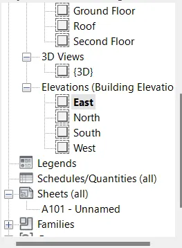
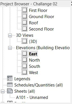
- Now you will be seeing the level in elevation view.
- Now select the elevation view
Step-3)
- Now Rename the Level 1@ 0' as ground level.
Step-4)
- Rename the lavel 2@ 10' as First Floor
Step-5)
- Go on the architecture toolbar and select the level option from datum ribbon.

Step-6)
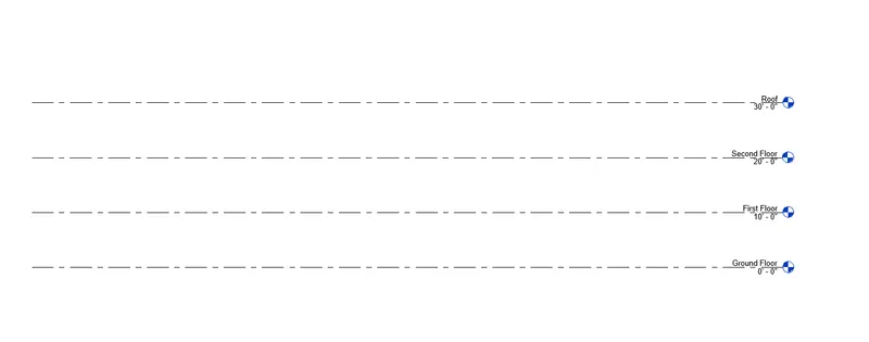
- Add level 3 @20' as Second Floor.
- And add level 4 @30' as Roof.
Step-7)
- Now add Grid
- Choose grid tools from Atchitecture toolbar

Step-8)
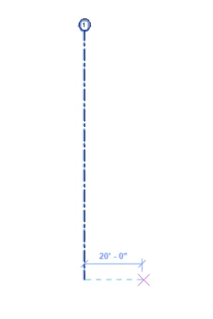
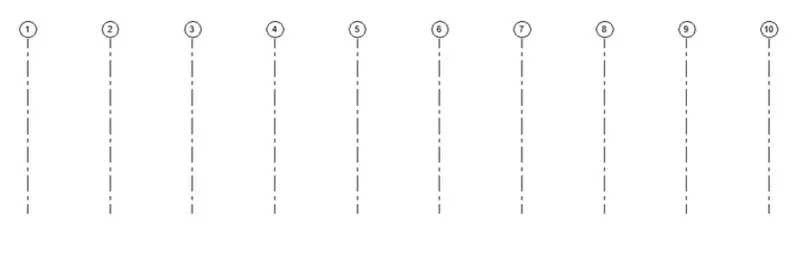
- Add longitudinal grid from 1 to 10 @ 20' spacing
STEP-9)
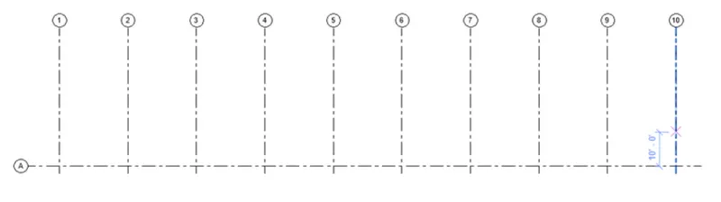
- Add transvers Grid as A,B,C,D,E @10' spacing
RESULT-
- Ground floor @0'
- First Floor @10'
- Second Floor @20'
- Roof @ 30'
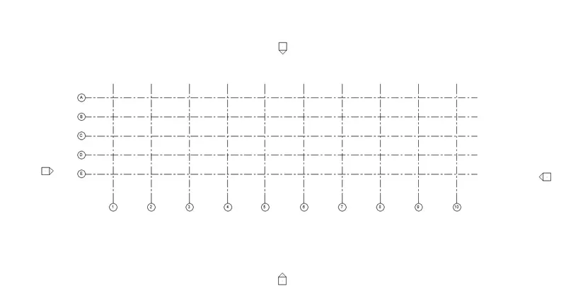
- grids transvers Grid A,B,C,D,E @10' Spacing
- longitudinal grid from1 to 10 @20' Spacing
Ans-5)
AIM- To draw a residential plan and create a conceptual view.
INTRODUCTION
• REVIT
- Autodesk Revit is a BIM software means a Building Information Modelling.
- Autodesk Revit used by civil engineers, architects, landscape architects, structural engineers MEP engineers, designers, etc for detailed desiging and drawing.
- Autodesk Revit is used for detailing of architectural drawings, structural drawings, MEP detailing drawings.
- Autodesk Revit is used for 2D as well as 3D modelling.
- It automatically updates floor plans, elevations, and sections as your model develops.
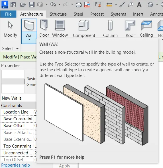
• Wall tool
- Wall tool from build tab from architecture ribbon is used to draw the walls with required height, material, thickness, etc.
- We can create walls as per requirement.
- We can edit wall properties from properties option
• View toolbar
- View toolbar includes tools like graphics, presentation, create, sheet composition, windows, user interface, etc.
- Graphics tab includes view template, visibility/graphics, filters, thin lines, show hidden lines, remove hidden lines, cut profie, etc
- Presentation tab includes render, render in cloud, render gallery, etc.
- Create tab includes 3Dview, section, callout, plan views, elevation, etc.
- Windows tab includes switch windows, close inactive, tab views, tile views, etc.
• Visibility tool
- wireframe
- CONCEPTUAL
- shaded
- realistic
- hidden lines
- consistent colors
- ray trace
PROCEDURE
STEp-1)
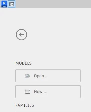
- Open Autodesk revit Software
- go to new option from Models
- Go on File Menu then go on project option
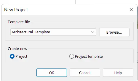
STEP-2)
- Nw select project and press ok
- select project as architectural tempelate
STEP-3)
- Now from Architectural toolbar select wall tools.
STEP-4)
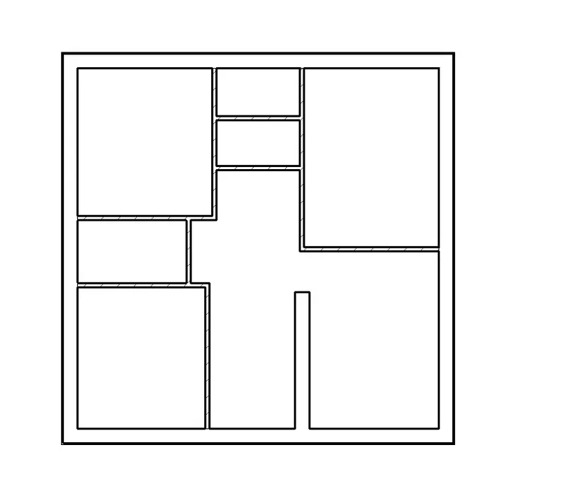
- Now draw residental area using wall tools.
STEP-5)
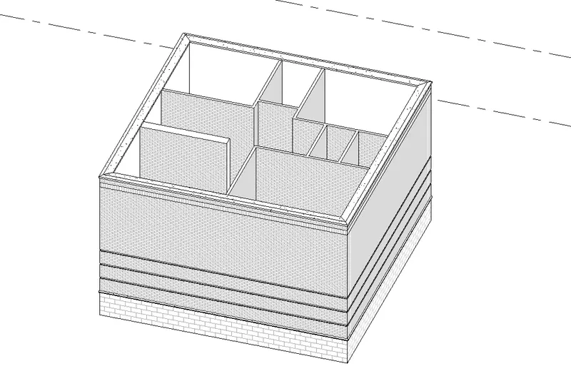
- Click on the 3D view option from upper right part of revit display
STEP-6)
- click on the graphic dispaly setting option from bottom left of page.
- then select the shaded view.
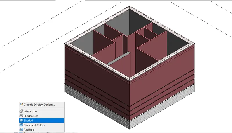
STEP-7)
- concept of view.
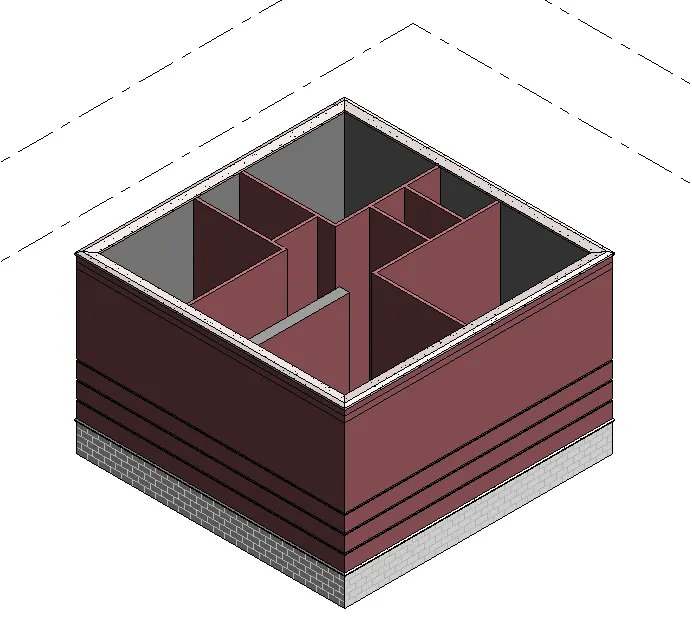
RESULTS-
- Conceptual View
Ans-6)
AIM- To add dimensions, components to residential plan.
INTRODUCTION
• REVIT
- Autodesk Revit is a BIM software means a Building Information Modelling.]
- Autodesk Revit used by civil engineers, architects, landscape architects, structural engineers MEP engineers, designers, etc for detailed desiging and drawing.
- Autodesk Revit is used for detailing of architectural drawings, structural drawings, MEP detailing drawings. o Autodesk Revit is used for 2D as well as 3D modelling.
- It automatically updates floor plans, elevations, and sections as your model develops.
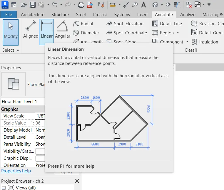
• Annotate toolbar-Linear
- aligned dimensions tool is used to place dimensions between references, or between multiple points.
- As you move the cursor over the dfrawing area, the reference points that you can use for dimensions are highlighted.
- Press tab to move from one reference point to another for elements that area close to one another.
• Instances
- Instances are individual graphical/geometric elements placed in a Revit model e.g. a single Wall, or a single Door, or any other single element.
- As a subset of Revit Elements, Instances inherit a series of Parameters from their Category and Type and might have instance parameters as well that only belongs to that single instance.
- The single element attatched to the wall is door, that door we call as instance, as shown below.
PROCEDURE
STEP-1)
- Add doors to the resident plan drawing
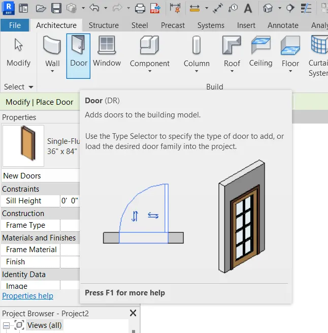
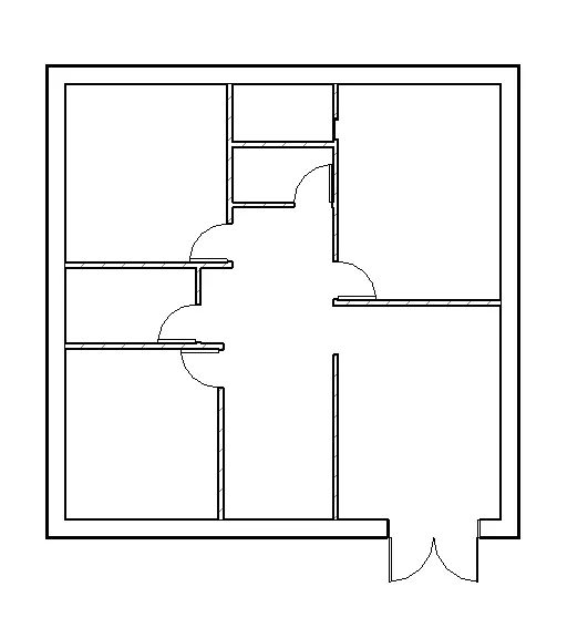
STEP-2)
- planAdd Windowsto the residental
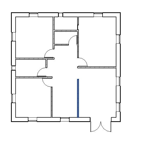
STEP-3)
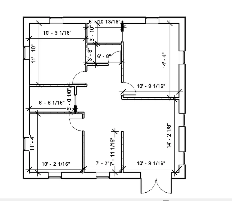
- Add annotation - linear to the residential plan
STEP-4)
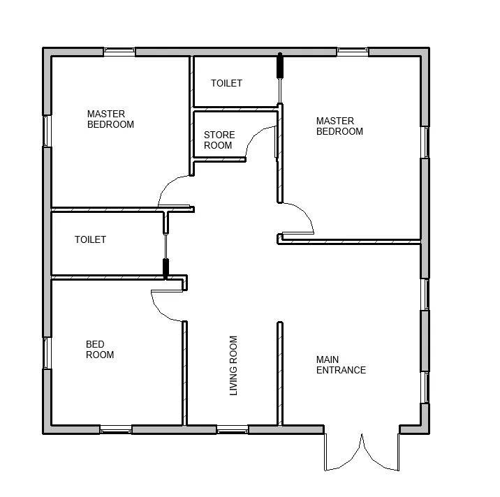
- Now add text to the plan and delete dimensions.
-

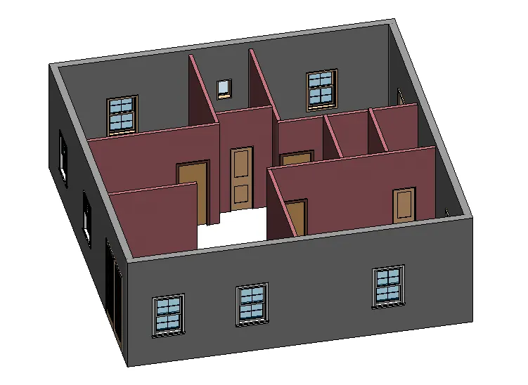
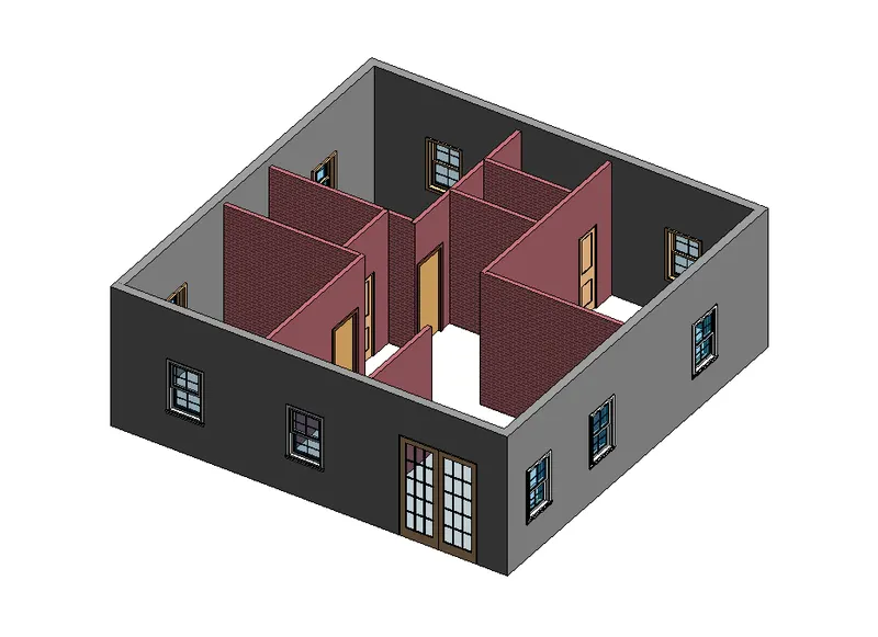
RESULTS-
- all the components and text is added to the residential plan.
Ans-7)
AIM- To add elements such as tables, chair, couch, bed, lamps, dining table, (furniture details etc to the residential plan.
INTRODUCTION
• REVIT
- Autodesk Revit is a BIM software means a Building Information Modelling.
- Autodesk Revit used by civil engineers, architects, landscape architects, structural engineers MEP
engineers, designers, etc for detailed desiging and drawing. - Autodesk Revit is used for detailing of architectural drawings, structural drawings, MEP detailing drawings. o Autodesk Revit is used for 2D as well as 3D modelling.
- It automatically updates floor plans, elevations, and sections as your model develops.
• Instances
- Instances are individual graphical/geometric elements placed in a Revit model e.g. a single Wall, or a
single Door, or any other single element. - As a subset of Revit Elements, Instances inherit a series of Parameters from their Category and Type and
might have instance parameters as well that only belongs to that single instance. - The single element attatched to the wall is door, that door we call as instance, as shown below.
PROCEDURE-
STEP-1)
- Add doors to the residential plan drawn
STEP-2)
- Add window to the residentals plan
STEP-3)
- Now add furniture details bu using load family tools.
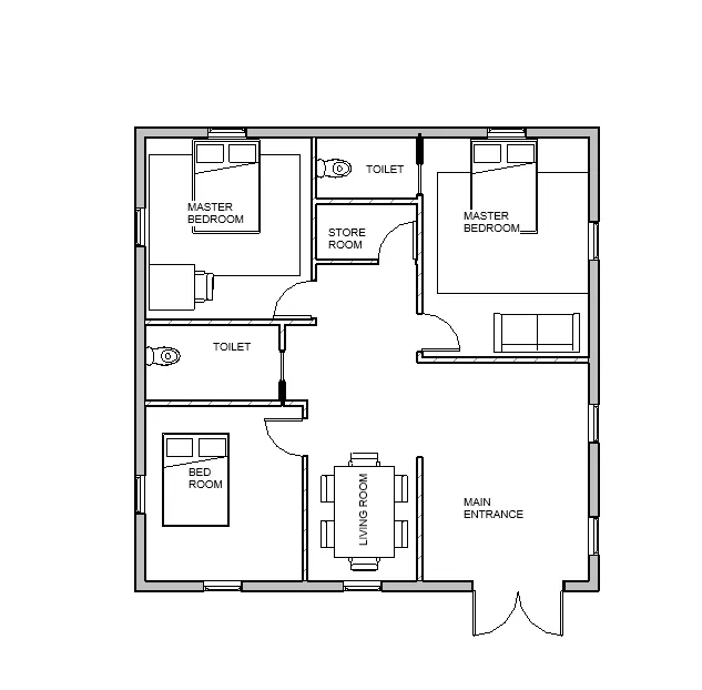
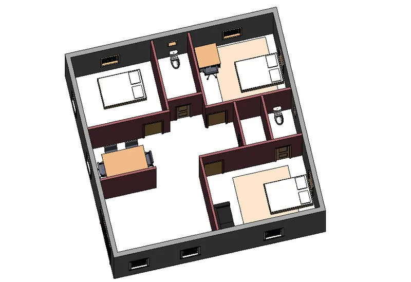
RESULT
- Elements are added to the residental building