Creating Kitchen layout, Hatching of Architectural elements and sectional view of an Industrial Building in AutoCad
1.AIM
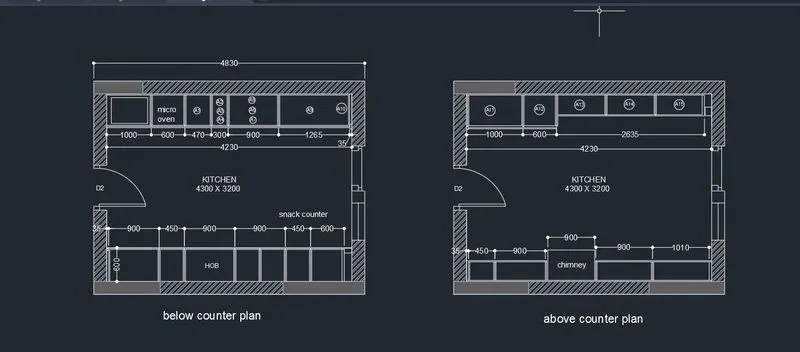
To create the layout of kitchen as per industry standards using the various commands in Auto CAD.
INTRODUCTION OF HATCHING
- The hatch command in AutoCAD is used to fill patters inside an enclosed area.
- The patterns are hatched, gradient and solid fill.
- The gradient patterns are defined as a smooth transition between two colors.
- The number of hatch lines represented in any patterns can be adjusted with the help of the Hatch pattern scale.
PROCEDURE
- To create a new drawing sheet .
- Type UN to set the units of current format of measure.( MILLIMETERS).
- Type LIMITS
- to set the maximum dimension limits on the particular page.
- Type L - Line commands allows to creating a line where the end points allows creating a line where the end points are dimensional co-ordinates.
- TYPE XLINE’ to draw the infinity length of line, can be draw it free or set it to be Horizontal or Vertical, follow a certain angle.
- To analyze the all dimension of kitchen area.
- The wall thickness of exterior in 230mm and interior in 150mm.
- Type OFF – offset command to create a new object that specified distance from an existing objects or through a specified points.
- Type Tr– Trim command is used to trims off an objects cutting the extra edges on objects.
- Type Text to create the text ( SINGLE or MULTI ), select and change the properties of standard size.
- If we create the text, therefore changed the text height by select the object, right click and then to go properties , then to change it.
- COPY – this commands is used to selected objects from a given square to destination, learning a copy at the originally selected location.
- Type H to hatch the patterns to fill inside a enclose area.
- Command ..BLOCK to save the objects.
- After saved it, to Command .. INSERT to plot the same diagram forever at the drawing file. This is used to save the accessories in the house for easily plot the diagram.
- If we given different name for easily identify the objects.
- Finally, to save the diagram .
RESULTS
The diagram of the Layout of kitchen is drawn as per dimensions using the software of Auto.
DIAGRAM
2.AIM
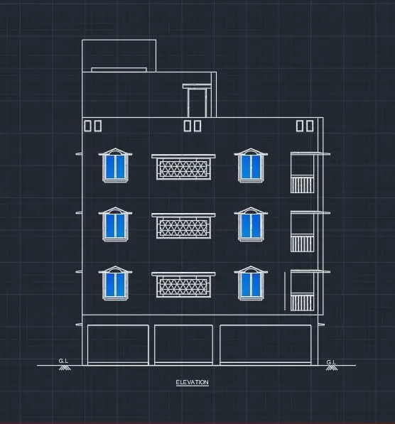
To draw the elevation of G+3 building using the various commands in Auto CAD.
INTRODUCTION OF ELEVATION
- An elevation drawing is the view that you would see in real life as you stood on the wall floor or ground and looked at the wall.
- This view can be either an exterior or interior view and it convey the information about the outlook.
PROCEDURE
- To create a new drawing sheet .
- Type UN’ to set the units of current format of measure.( MILLIMETERS)
- Type LIMITS’ to set the maximum dimension limits on the particular page.
- Type L - Line commands allows to creating a line where the end points allows creating a line where the end points are dimensional co-ordinates.
- TYPE XLINE to draw the infinity length of line, can be draw it free or set it to be Horizontal or Vertical, follow a certain angle.
- Before we started the elevation baseline have to study and understand the plan of building and then to plot the elevation baseline.
- We take the all reference line from the plan to easily drafting the elevation accurately .
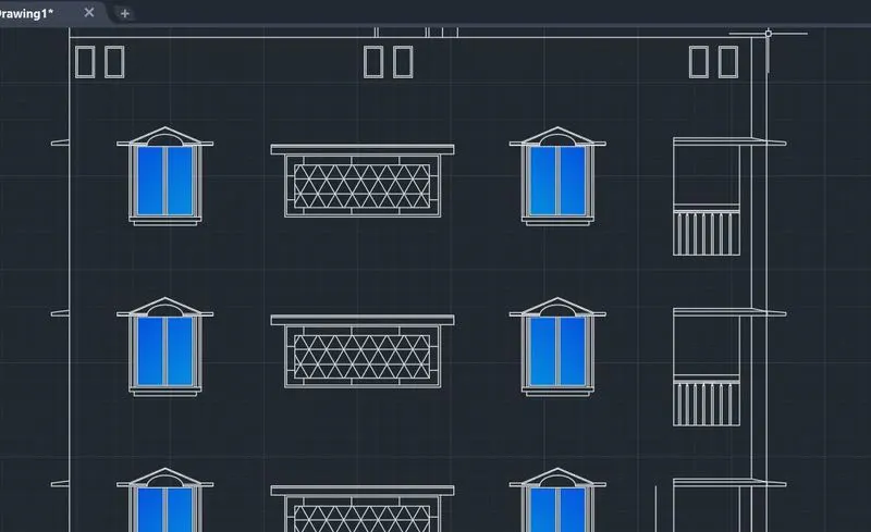
- This comes after to follow the door and window areas of elevation properly.
- Type OFF – offset command to create a new object that specified distance from an existing objects or through a specified points. ( For EX .. Rows and Column of the table.
- Type TR – Trim command is used to trims off an objects cutting the extra edges on objects.
- Type Text to create the text ( SINGLE or MULTI ), select and change the properties of standard size.
- COPY – this commands is used to selected objects from a given square to destination, learning a copy at the originally selected location.
- Command ..BLOCK’ to save the objects.
- After saved it, to Command .. INSERT’ to plot the same diagram forever at the drawing file. This is used to save the accessories in the house for easily plot the diagram.
- Type H to hatch the patterns to fill inside a enclose area.( Doors, Windows and wall).
- Finally, to save the diagram.
RESULTS
The diagram of the Elevation of G+3 buildings is drawn as per dimensions using the software of Auto.
DIAGRAM
3.AIM
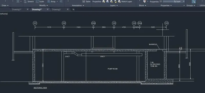
To create the Sectional view of an industrial building using the various commands in Auto CAD.
INTRODUCTION OF SECTION VIEW
- Click Layout tab create View panel section drop down full and the view of we want to use as the parent view
- Click the drawing area to indicate the start point of the section line.
- A full section view is generated by running the cutting plane through the entire length of the object being sectioned.
PROCEDURE
- To create a new drawing sheet .
- Type UN to set the units of current format of measure.( MILLIMETERS)
- Type LIMITS’ to set the maximum dimension limits on the particular page.
- Type L- Line commands allows to creating a line where the end points allows creating a line where the end points are dimensional co-ordinates.
- TYPE XLINE’ to draw the infinity length of line, can be draw it free or set it to be Horizontal or Vertical, follow a certain angle.
- We found that all intercourse area of the sectional plan to absorbs the identity of view at cross sectional
- Type OFF – offset command to create a new object that specified distance from an existing objects or through a specified points. ( For EX .. Rows and Column of the table.
- Type Tr– Trim command is used to trims off an objects cutting the extra edges on objects.
- Type Text to create the text ( SINGLE or MULTI ), select and change the properties of standard size.
- COPY – this commands is used to selected objects from a given square to destination, learning a copy at the originally selected location.
- Type H to hatch the patterns to fill inside a enclose area.( Doors, Windows and wall).
- Finally, to save the diagram.
RESULTS
The diagram of the Sectional view of an industrial building is drawn as per dimensions using the software of Auto.
DIAGRAM