Creating Kitchen layout, Hatching of Architectural elements and sectional view of an Industrial Building in AutoCad
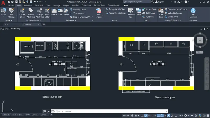
3) AIM: To create the kitchen layout by using autocad software.
INTRODUCTION: A kitchen layout as per given figure is drawn by using proper commands. A detailed explanation of sketch is given below.
PROCEDURE:
- Command REC for rectangle to create outer wall of the plan.
- Use O commmand for offset to create inner walls.
- Use L command or REC commmand to draw the plat form and different accesories inthe kitchen or use ADC command to insert them by using predifined block objects.
- Use TR command to remove the exxta portions.
- H command for hatching.
- DLI,DCO commands for dimensions.
- DT commaand for text.
LAYOUT:
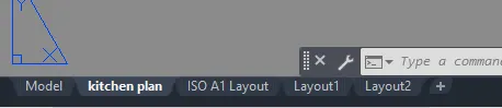
- Layout tab is visible on the bottom left side if not go to view and make it on.
- By clickinng it you will enter in to latout page.
- First thing is to change the name of layout it is done by right click on the layout tab or by command LAYOUT.
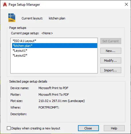
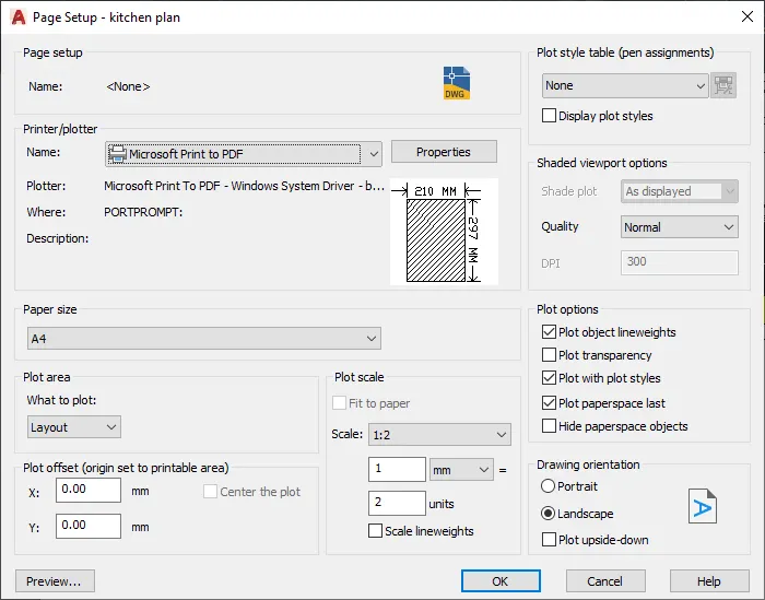
- Set the page by going in to page setup manager by right click on the layout tab.
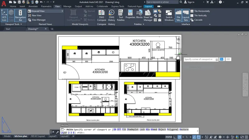
- Use MV command to create a drawing file in that we have different options like multiple ports, layers, object, new etc choose one to draw.
- Use MS command to enter in to modle space to edit drawing.
- Set the drawing in to defined scale and lock it by using MV or by going in to properties.

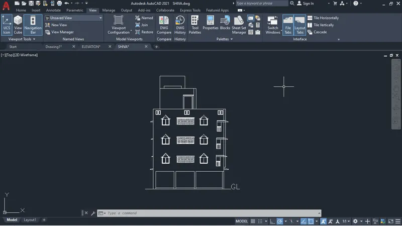
Aim: By taking reference of plan from challange 7 drawing elevation.
procedure:
- Open the plan drawing use XL command and draw the vertical lines where there are walls,columns, beams, doors, windows.
- Remove the extra lines by TR command.
- Use copy(CO), MIRROR(MI), commands when ever it is use.
- Draw the doors and windows by using line command or REC commmand or use ADC to use predifined doors and windows.
- Block(B) them and insert(I) them at particular place shown in the plan.
- Use hatch(H) command to hatch the different architectural elements.
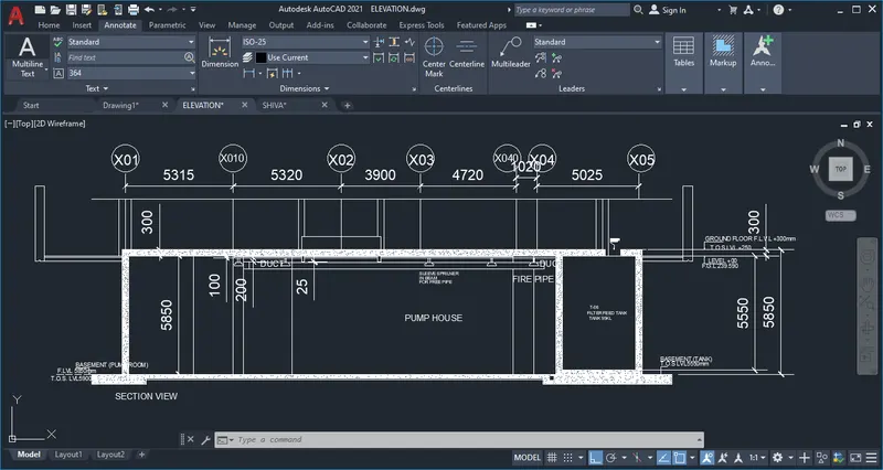
AIM: To create a sectional view of industrial building as shown in the figure.
PROCEDURE:
- By using the dimensions draw the elevation part by Line command. Use TR to modify it when necessary.
- Use H commmand to hatch as showwn in the figure.
- Use dt to text.
- Use C for circle use ATTDEF to attribute and block (B) it and insert it as shown in fig.
- Use ATTED to edit text as shown inn thhe fig.
- DLI for dimensions and DCO for continue.
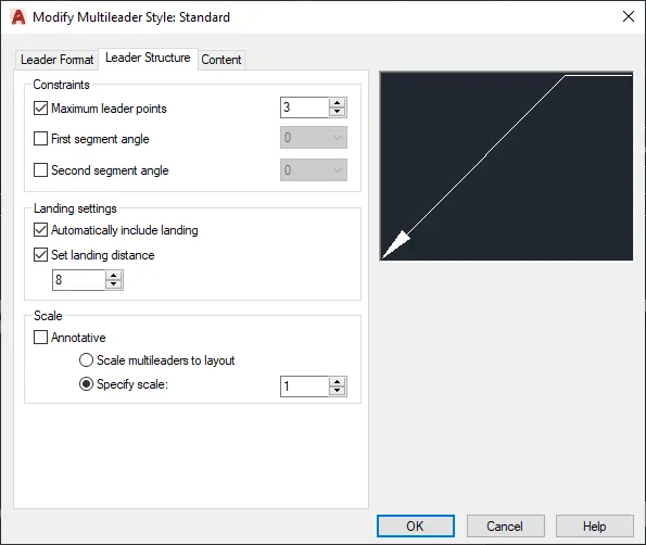
- Use ML for multileader option to poinnt out basement and different levels.