Creating Conceptual mass in REVIT and Creation of Sinusoidal curve and a Parametric stadium using Dynamo
Solution.1)
Aim: Using Dynamo create a set of sinusoidal points and create a curve and create a surface out of the curve.
Procedure:
- Open a new Archtectural File.
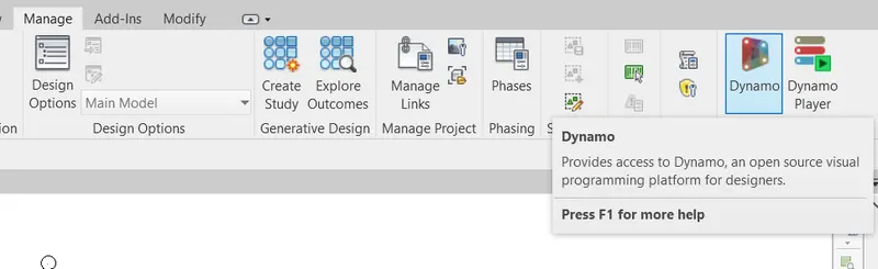
- Go to Manage tab and select Dynamo Option.
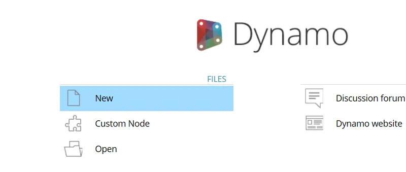
- Dynamo screen will open-up, Select a New File.
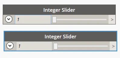
- Create Integer tab for taking input.
- Create a list of points, using Range option.
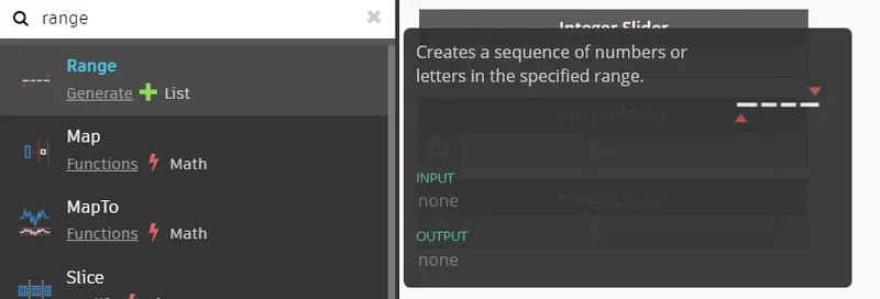
- Now, connect the integer into the input of range option.
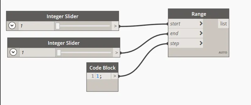
- Similarly, add the following nodes as shown in below figure to create a Sinusoidal Curve.
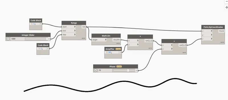
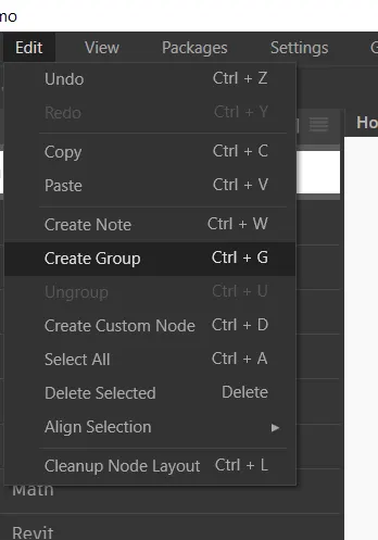
- Now, we can group the nodes doing operations to create the input points as Sinusoidal Points. For that, we can select all these intermediary nodes and go to Edit, and click on Create Group Option.
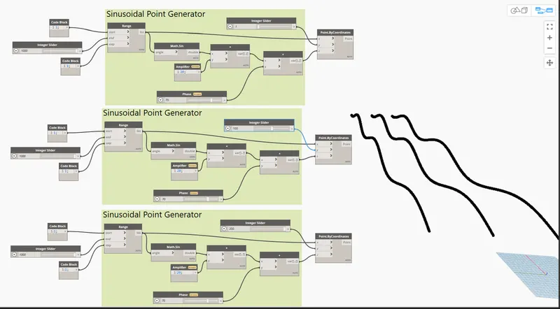
- Now, afer the grouing is done, copy paste all the nodes and paste twice to make three sinusoidal curve.
- Add three slider to change the values of y-coordinate to diffrentiate the curve.
- The final look of the three curves is shown below.
- Now, to create the surface add the following nodes.
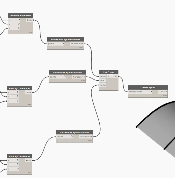
- The surface connecting the points of Sinusoidal Curve has been generated.
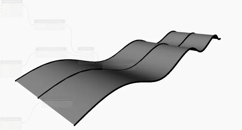
Result: A set of Sinusoidal Points is made and then a surface connecting this points is also made as shown in above figure.
Solution.2)
Aim: To create a conceptual layout of floor plan in dynamo . Using the tools available in dynamo link the lines to appropriate model elements in Revit by choosing the wall types and wall parameters. Make use of the sliders to slide through the height of the wall and length of the wall.
Procedure:
- Open a New Dynamo File.
- For creating a conceptual Wall layout, we need to have for points at the corner of the floor plan. Hence, we need to create four points. One is fixed at orgin for reference.
-
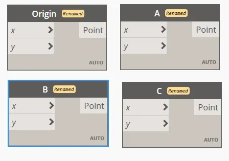
- Now, to take input for this point we need either codeblocks or number slider nodes.
- Connect the input to the coordinates.
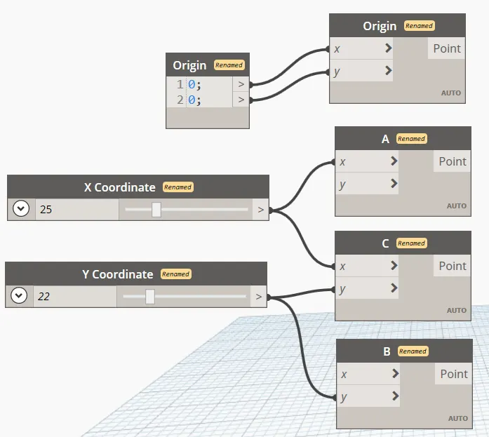
- Now, we need to make the line joining this point. So we will use Line node to join the points A,B and C.
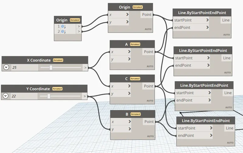
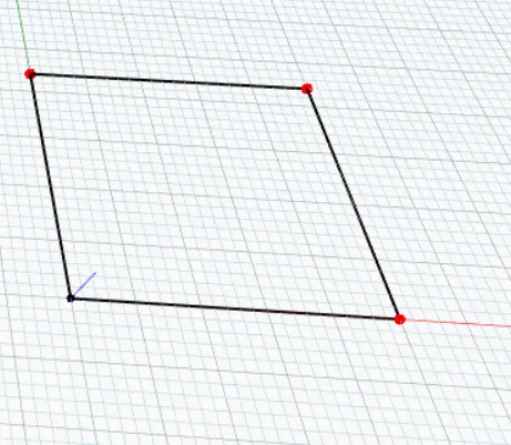
- We can that line has been made joining the points.
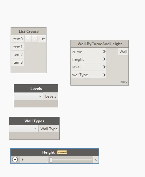
- Now, to create the wall, we need five nodes i.e., List to collect all the lines as a list, Wall Type, Slider to adjust the height of wall, Levels to assign the level and wall by heights node as shown in below figure.
- Now connect all the nodes as shown in below figure.
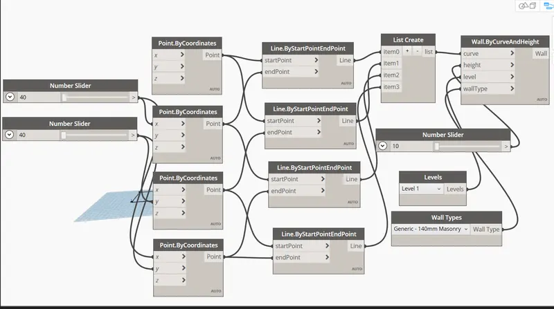
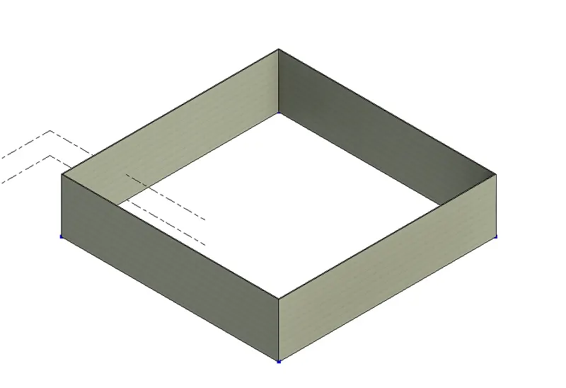
- Now, go back to Revit Workspace, we can find the layout designed in Dynamo in Revit Workspace.
Solution.3)
Aim: Create an array of model elements in Revit. Use dynamo to vary the properties of model elements by using the slider or code block.
Procedure:
- Open Architectural Template, and place 6 Architectural Column in two row as shown in below figure.
- Now, go to Manage Tab, and Open Dynamo Workset.
- Now, open a new Dynamo File.
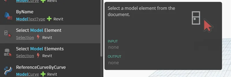
- Add a node named as Select Model Element.
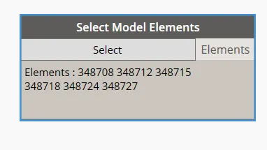
- Now, click on select and go to Revit to select all the columns.
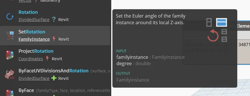
- Add another node named Family Instance Set Rotation.
- Now, add a number slider to change the rotation angle of the column.
- Connect the nodes and try to change the rotation angle, we can observe the live rotation of column orientation in Revit Workspace.
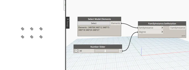
Result: We have successfuly changed the parameter associated with a element in Revit using Dynamo.
Solution.4)
Aim: Create a conceptual mass in Revit and develop a parametric column by dividing the surfaces and apply the concepts similar to used in parametric walkway modelling. Use triangular bent or square shaped panels to add finish to the parametric column.
Procedure:
- Open a new Revit Family File.
- Choose Metric Mass as a new Template.
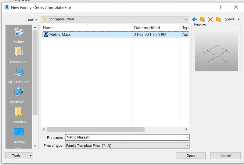
- New wokspace will get open.
- Open any of the elevation view and another level at 10', so that we can design a parametric column till this level.
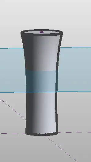
- Now, draw a column with variation in diameter.
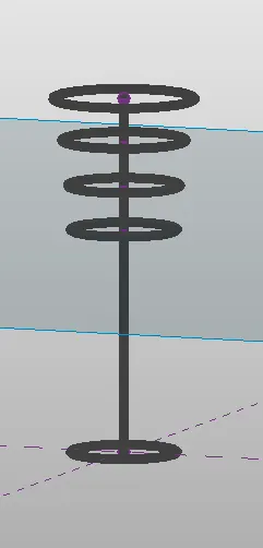
- Now select all the circular ring and click on Create Form.
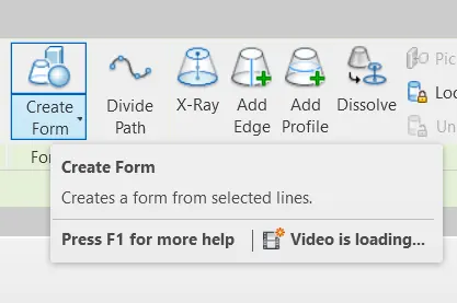
- Final Look of the column will look like as shown below.
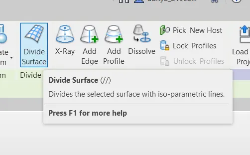
- Now, select the Surface and click on Divide Surface.
- Now, go to property browser, and select the Pattern of Suface Division( we have selected Hexagon)
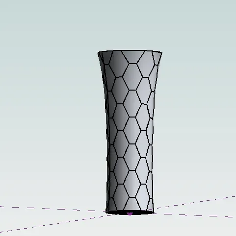
Result: I have a created a conceptual mass of Column and divided the surface into hexagonal pattern similar to done for Walkway Modelling.
Solution.5)
Aim: Use Dynamo to work on developing a Parametric Stadium. List your parameters and use the visual programming approach to complete the modelling, You can use the concepts discussed in parametric high rise tower in class for reference.
Procedure:
- Open a new Architectural File.
- Go to Manage Tab and Select Dynamo to open a new Dynamo File.
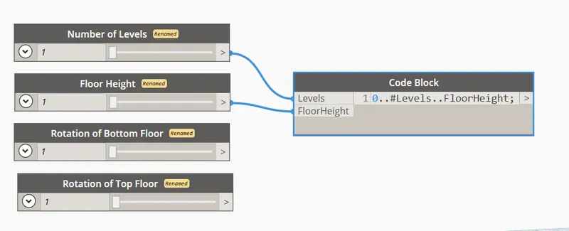
- Now let us add four number slider to manage the Number of Levels, Floor to Floor Height, Rotation Angle for Bottom and Top.
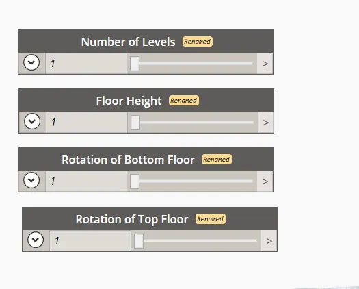
- Now, add code blocks to connect Levels and Floor Heights.
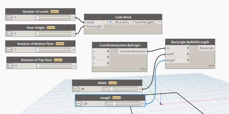
- Now, let us add the Rectangle by width length and coordinate system also add coordinates with origin.Also add a slider to adjust the width and length of rectangle.
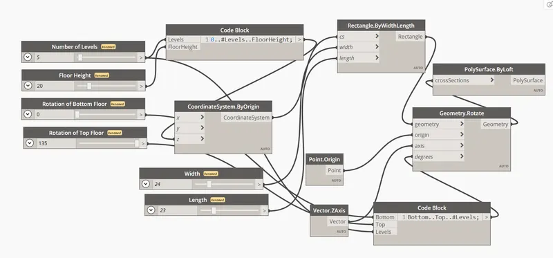
- Now let us add the Geometry to rotate, code block to add rotation angle parameter. Also connect the Level and Floor Height parameters to Coodrniates system and add suface by loft node to create a surface.
- Connect the nodes as shown in below figure.
- The final look of the Parametric structure is as shown in figure.
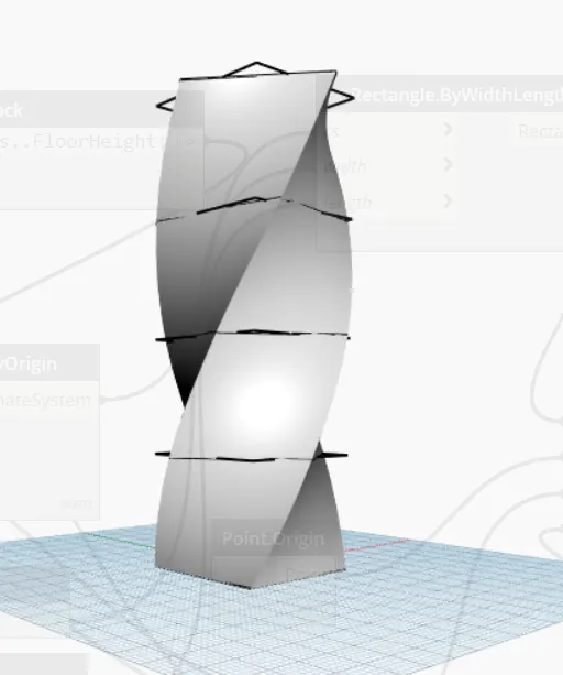
Result: The desired Parametric Structure has been made in Dynamo.