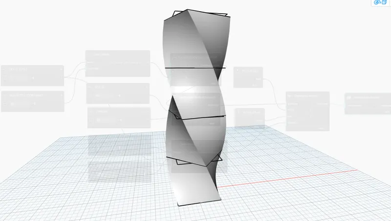
Creating Conceptual mass in REVIT and Creation of Sinusoidal curve and a Parametric stadium using Dynamo
- ALL Q ANS. LINK :- https://drive.google.com/drive/folders/1L0RYGxAv5Vi9lKzSso4VT1QRkA9bMYpk?usp=share_link
- CREATE A CONCEPTUAL MASS IN REVIT AND CREATION OF SINUSOIDAL CURVE AND A PARAMETRIC STADIUM USING DYNAMO :
- QUESTION : 1
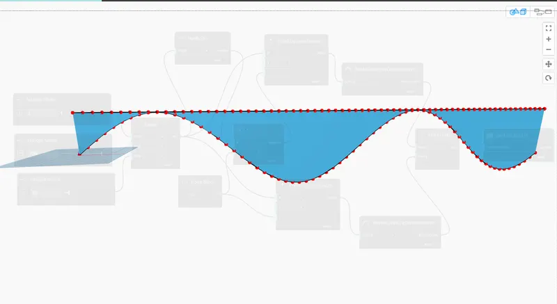
- Using Dynamo create a set of sinusoidal points and create a curve and create a surface out of the curve.
- ANSWER :
- AIM :
- TO CREATE A SET OF SINUSOIDAL POINTS AND CREATE A CURVES AND SURFACE OUT OF THE CURVE USING DYNAMO
- PROCEDURE :
- STEP 1
- start the revit software
- and selct the archictural templet
- save the file as dynamo
- STEP 2
- then go to the manage tab
- from the visual programming
- click on dynamo
- then homepage of dynamo is open shown below
- STEP 3
- click on NEW option from homepage
- then workspace of dynamo is open shown below
- STEP 4
- go to the labary and type integer slider
- and take the three no of integer slider by using copy option
- rename the interger slider as START , END AND STEP
- then give the value of that as 1 ,700 and 10 respectively
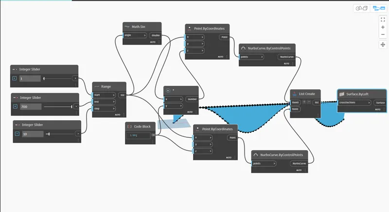
- ater that create a range
- so that go to the labary and type range
- and connect the start , end and step to the range
- take a point by coordinate
- copy this point by coordinate for making to sinusoidal curve point
- and code block also copy the code block
- then type a math.sin and selct it
- connect the range to x coordinate
- and range to math.sin
- and give the code block value as 50
- then connect the range to another x coordinate
- type a product and select it
- connect the code block to y coordinate so we get a another sinosidal line
- then connect the code block to the y coordinate
- and connect the math.sin to y coordinate
- connect the math,sin to product x coordinate
- and code block to product y coordinate
- then connect the product varient to z coordinate then curve is created
- to create the sinosidal curve so that
- type nurbs by control point and insert it
- and then copy it and place at proper poisition
- then type list
- and click on list create
- then connect the point by coordinate to the nurbs by control point so we get curve line as shown in results
- we have two curve line so that
- go to the list code and click on plus sign
- and connect the nurbs by control point to itom 0
- and also connect the nurbs by control point to itom 1
- so we created curve point in this way .
- now we have to make surface by loft option
- so that type the surface
- and select the surface by loft
- and connect the list to the surface by loft
- in this way surface is created .
- RESULTS :
- CODE BLOCK :
-
LINK :- https://drive.google.com/drive/folders/1L0RYGxAv5Vi9lKzSso4VT1QRkA9bMYpk?usp=sharing
- QUESTION : 2
- Create a conceptual layout of floor plan in dynamo . Using the tools available in dynamo link the lines to appropriate model elements in Revit by choosing the wall types and wall parameters. Make use of the sliders to slide through the height of the wall and length of the wall.
- ANSWER :
- AIM :
- CREATE A CONCEPTUAL LAYOUT OF FLOOR PLAN IN DYNAMO :
- STEP 1
- start the revit software
- then homepage of revit is open
- then click on NEW
- select the archictural templet
- click OK
- click on file option
- click ok save and save the project
- STEP 2
- go to the manage tab
- then click on dynamo
- then homepage of dynamo is open as shown below
- click on NEW option
- workspace of dynamo is open shown below
- STEP 3
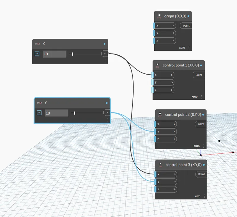
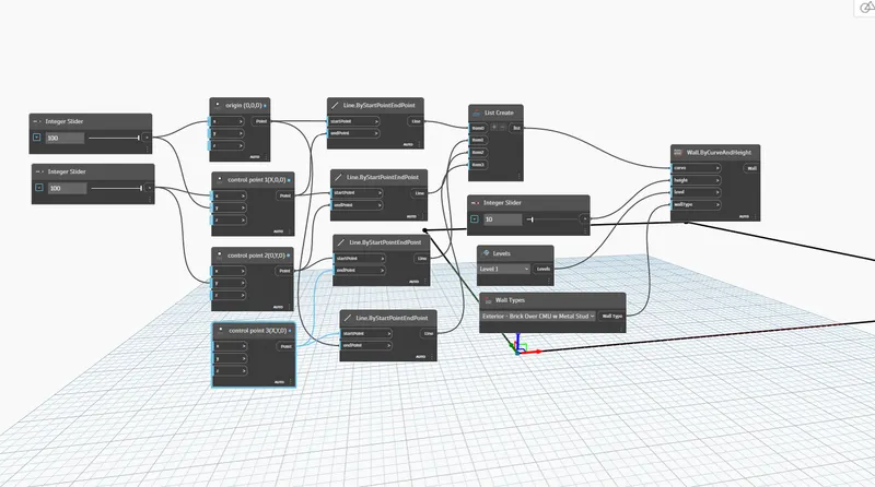
- go to the labary and tpe point by coordinate
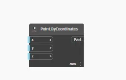
- take 4 no of point by coordinate
- and rename it as shown below
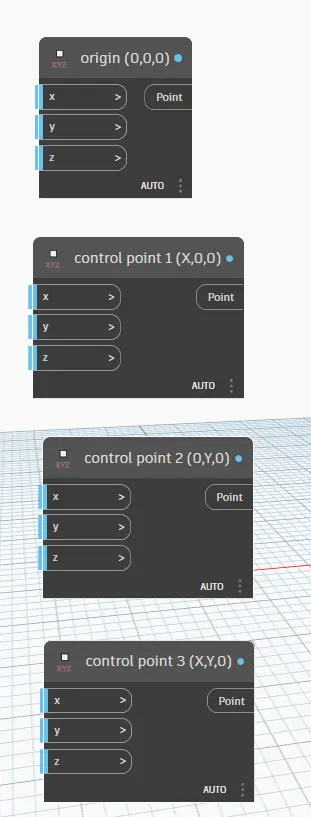
- STEP 5
- go to the labary and type number slider
- and take 2 no of number slider
- rename it as x and y as shown below
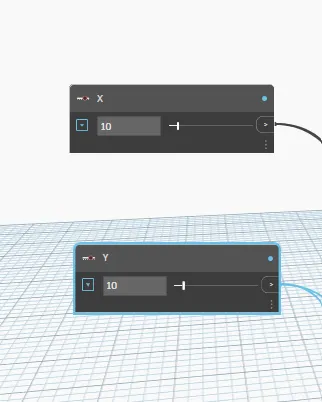
- then connect the x point to x control point
- and y coordinate to y control point
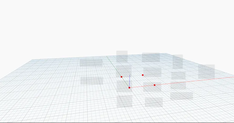
- the 4 point is genrated as shown below
- STEP 6
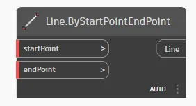
- go to the labary and type the line
- and click on line by start point end point
- take it 4 no as shown below
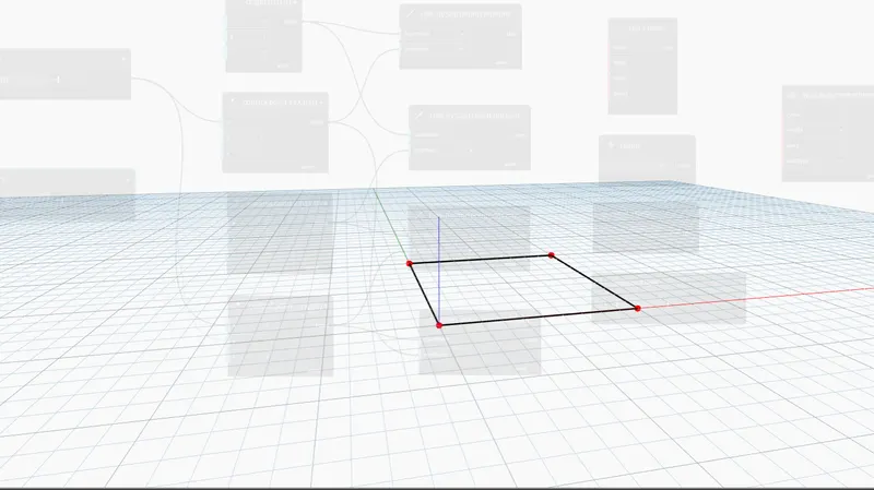
- then connect the start point and endpoint s shown below
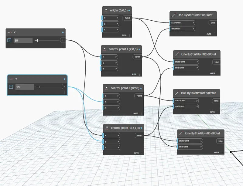
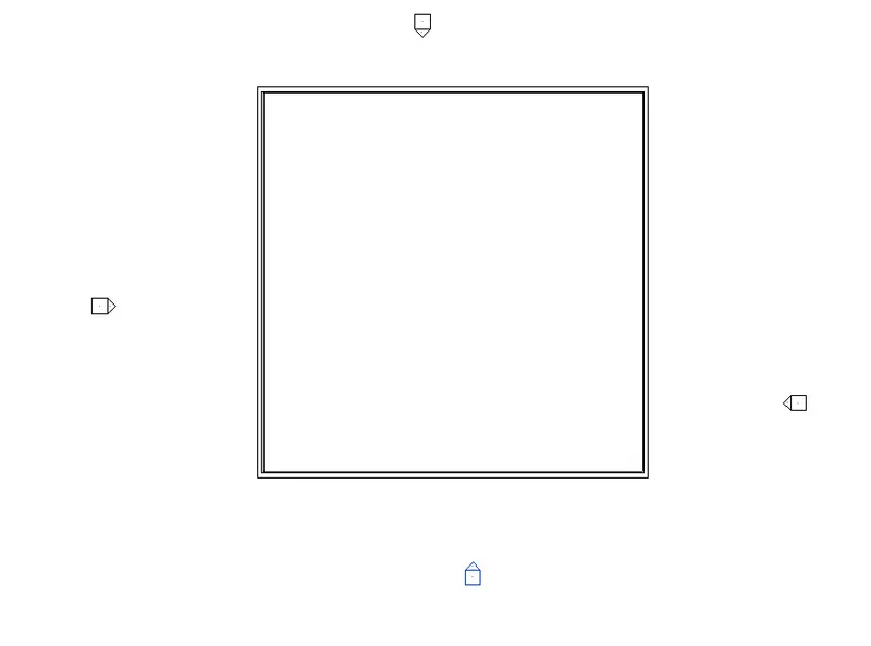
- our wall layout is created shown below
- STEP 7
- type list in labary and click on list create
- and click on plus butten and create the 4 itom shown below
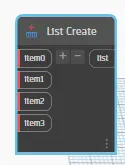
- and connect all lines to the leach itom created in list
- STEP 8
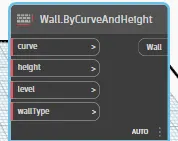
- go to tha labary and type wall
- click on wall by curve and height
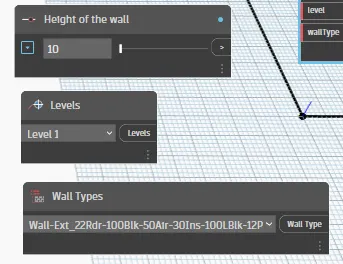
- then type level
- and give the lavel as level 1
- then take a wall type code and select the requried wall type shown below
- for height of wall take one number slider
- and rename it as height of wall
- and arranged it properly as shown below
- then connect the list code to curve
- the height code to height
- connect the wall type and level also
- in this way our wall is created using dynamo
- then minimize the dynamo
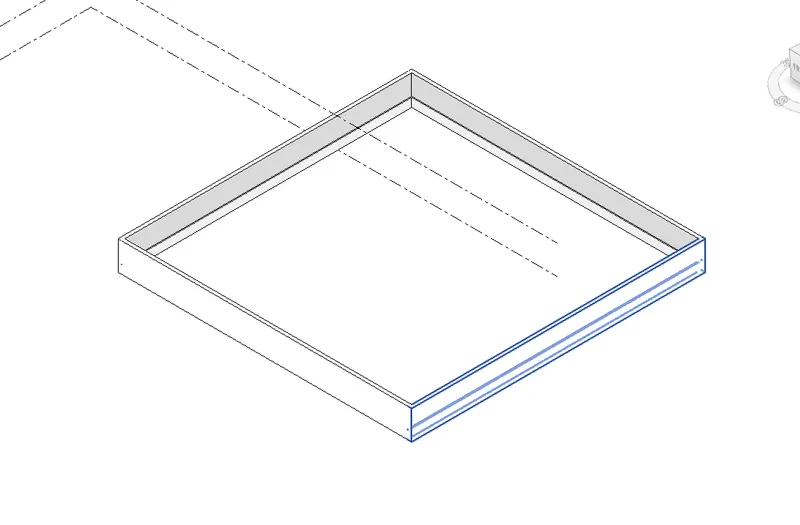
- and go to the revit screen we see the wall created by code shown in results
- RESULTS :
- CODE BLOCK :
- WALL :
- 3D VIEW OF WALL :
- QUESTION : 3
- Create an array of model elements in Revit. Use dynamo to vary the properties of model elements by using the slider or code block
- ANSWER :
- AIM :
- CREATE AN ARRAY OF MODEL ELEMENT IN REVIT USING DYNAMO
- PROCEDURE :
- STEP 1
- start the revit software
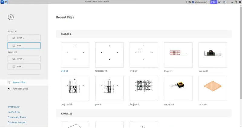
- then homepage of revit is open as shown below
- click on new option from that homepage
- select the template as archictural
- and save the file by giving proper name
- STEP 2
- go to the manage tab
- click on DYNAMO
- then homepage of dynamo is open as shown below
- then click on NEW option
- then work space of dynamo is open
- STEP 3
- minimize the dynamo tab
- and go to the revit workspace
- click on archictural column
- and give the 4 column shown below

- STEP 4
- Again go to the dynamo
- then go labary and type slider
- click on integer slider
- then rename it as a angle shown below
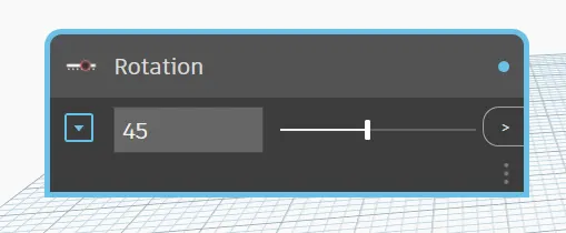
- then give the rotation angle as 45 degree
- then go to the liabary type model element and take it shown below
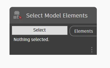
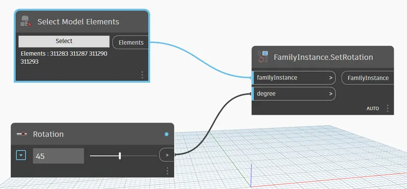
- then type rotation and click on set rotation . code shown below
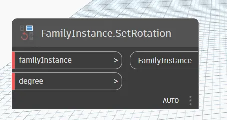
- then go to the code select mode element and click on select
- then minimize the dynamo window
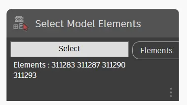
- and go to revit window select the column which alrady placed. select it by window selection process
- then go to the dynamo warkspace we see that element is selected shown below
- STEP 5
- Then connect the model element to family instance
- and rotation angle to degree
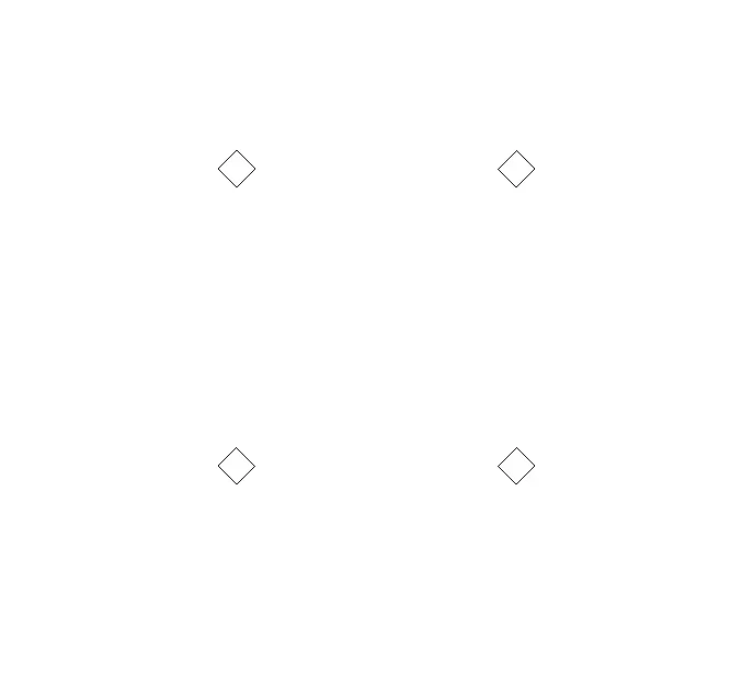
- in this we we rotate the column at 45 degree
- then minimize the dynamo warkspace
- and go to the revit we see the results show below
- RESULTS :
- CODE BLOCK
- ELEMENT :
- QUESTION 4 :
- Create a conceptual mass in Revit and develop a parametric column by dividing the surfaces and apply the concepts similar to used in parametric walkway modelling. Use triangular bent or square shaped panels to add finish to the parametric column
- ANSWER :
- AIM :
- CREATE A CONCEPTUAL MASS IN REVIT
- PROCEDURE :
- STEP 1 :
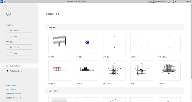
- Start the revit 2023 software
- then homepage of revit is open shown below
- STEP 2
- click on new option
- select the templet
- and click ok
- STEP 3
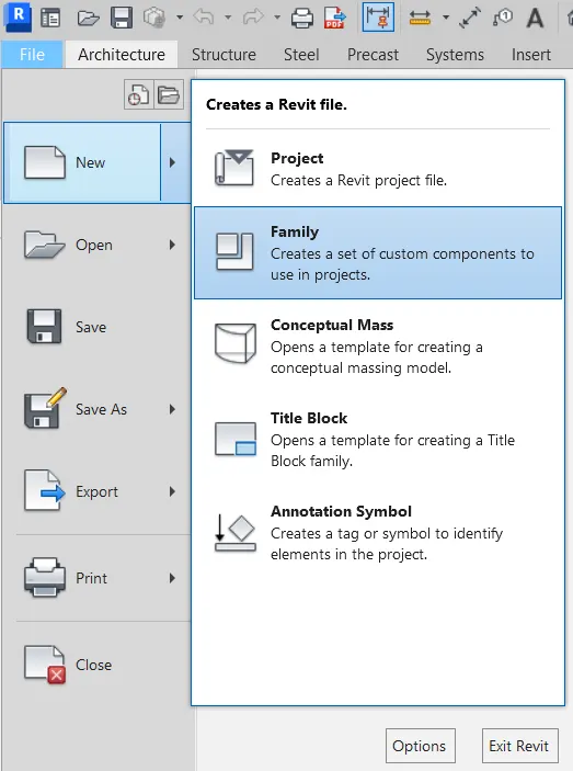
- again go to NEW option
- then click on conceptiual mass
- then enetr
- then select the matric mass
- and open it shown below
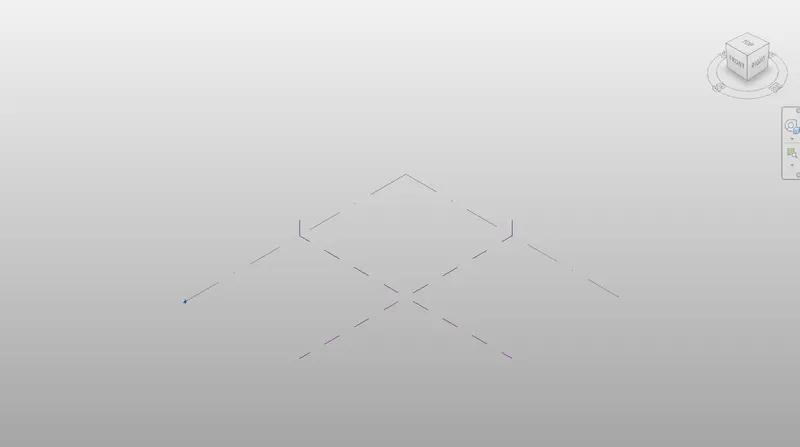
- STEP 4
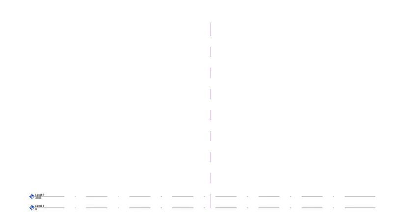
- there are just 1 level is created so that create a one more level ata a distance of 12'
- so go to the EAST elevation
- click on level 1
- select the pick line option
- give the offset of 12'
- and mark the another level shown below
-
- STEP 5
- Draw the spline line
- so that go to the floor plan
- then click on MODEL
- click on spline line
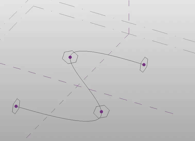
- and draw the spline line as shown below
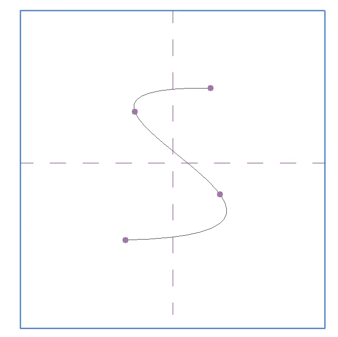
- 3D VIEW OF SPLINE :
- STEP 6
- Then set the plane
- so that
- click on set option also click on show option
- and select the point and set plane as shown below
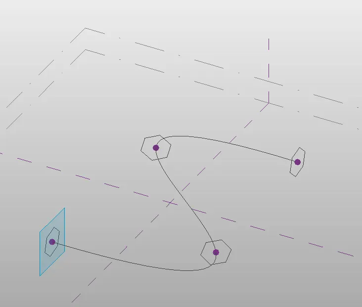
- set the plane to all four point
- STEP 7
- selct the curcumscribed polygon option
- click on midpoint of plane
- and give the height of polygon is 12' becouse we alrady created level at a distance of 12' shown below
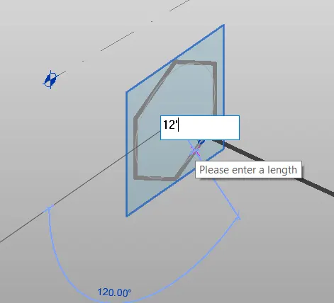
- provide this polygon to all four plane
- STEP 8
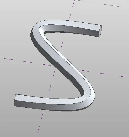
- create a solid form of curve
- so that click on create
- then select the line and polygon by pressing CTRL tab
- then click on create form
- selct the solid form
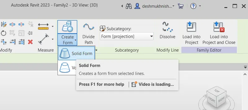
- and press enter
- solid form is created shown below
- STEP 9
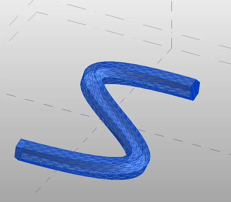
- then provide the trangular pattern to the curve
- to that just select the form
- so that select the all element by window selection process
- then go to the filter
- and click on just form option
- and click apply and ok
- again select the element by widow selection process
- and click on divide the surface
- then surface is divided as shown below
- STEP 10
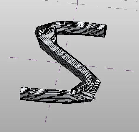
- Apply the triangular bend
- so that
- select the curve by window selection
- and click on divide the path
- and click ok
- again select the curve element and click on divide surface
- and go to the pattern section
- clcik on trangular option
- and provide the trangular band to the surface
- as shown below
- RESULTS :
- SPLINE SOLID SURFACE :
- TRIANGULAR BAND FORM :
- QUESTION 5
- Use Dynamo to work on developing a Parametric Stadium. List your parameters and use the visual programming approach to complete the modelling, You can use the concepts discussed in parametric high rise tower in class for reference.
- ANSWER :
- AIM :
- USE THE DYNAMO TO WORK ON DEVELOPING A PARAMERTIC STADIUM
- PROCEDURE :
- STEP 1
- start the revit software
- then homepage of revit is open shown below
- STEP 2
- click on NEW option
- select the templet as archictural templet
- and click ok
- STEP 3
- go to the manage tab
- click on DYNAMO
- then homepage of dynamo is open as shown below
- click on NEW option
- then workspace of dynamo is open
- STEP 4
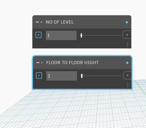
- type slider in labirary
- and click on integer slider
- take 2 no fo integer slider
- then rename it as shown below
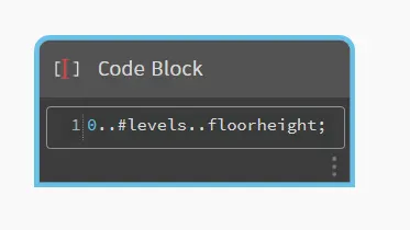
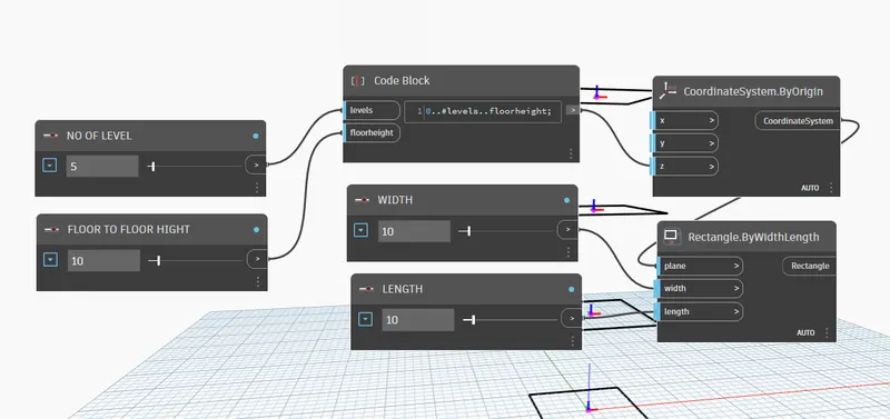
- then go to tha libary and type code block
- take one code block
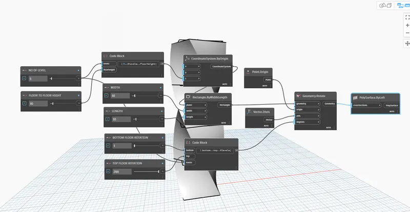
- and type in the code block as 0..levels..floorheight as shown below
- STEP 5
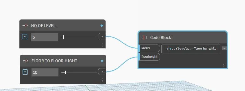
- Then connect the level to level
- and floor height to height as shown below
- STEP 6
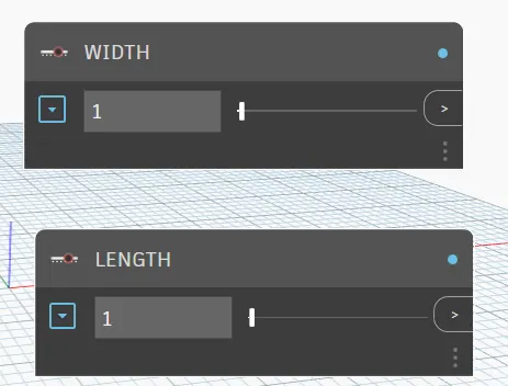
- go to the libary and type slider
- take 2 no of integer slider
- and rename it as length and width give the value as 10 as shown below
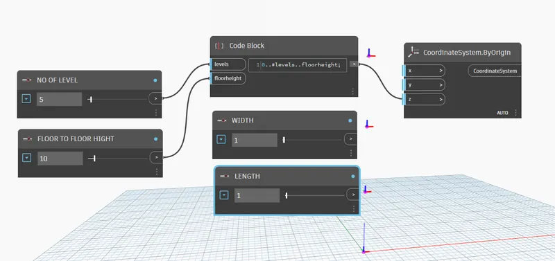
- then again go to the libary and type origin
- and take coordinate system by origin as shown below
- and connect the code block to z coordinate as shown below
- again go to libary and type the rectangle
- and select the rectangle by width length
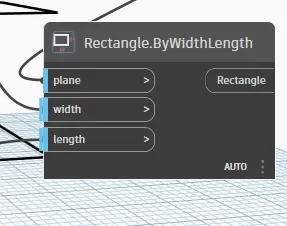
- then connect the coordinate to coordinate code
- and also connect the width to width and length to length code as shown below
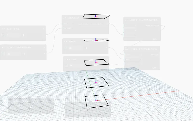
- STEP 7
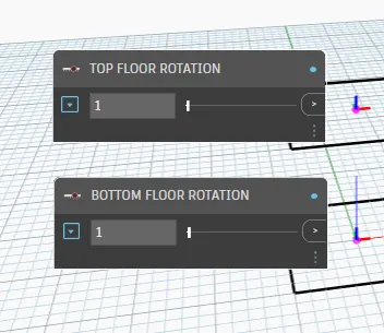
- again go to the labiry and type slider
- take two no of integer slider
- and rename it as shown below
- then take one code block
- in that code block type bottom..top..#levels as shown below
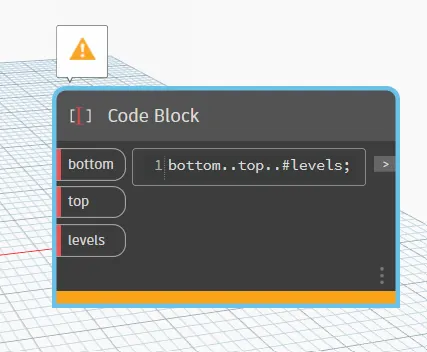
- then connect the bottem floor rotation to bottem
- connect the level to level
- and top floor rotation to top as shown below
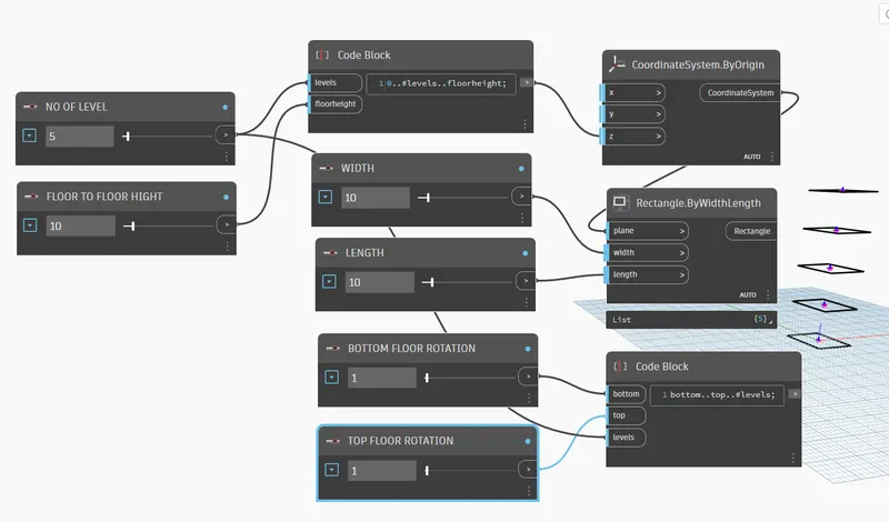
- STEP 8 :
- go to the libary and type origin
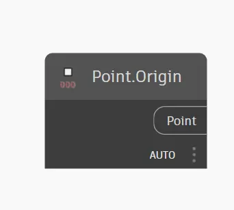
- and take point origin as shown below
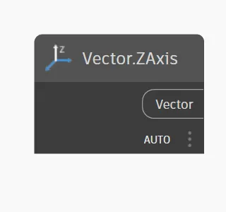
- then again go to libary and take victor z axis take it as shown below
- then type geometry rotate and take it shown below
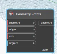
- and place all the code properly
- and connect the rectangle to geometry
- point to origin
- vector z axis to axis
- and degree to code block as shown below
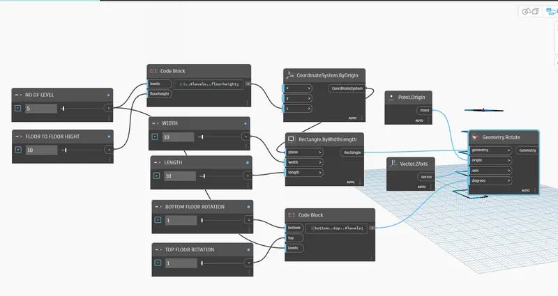
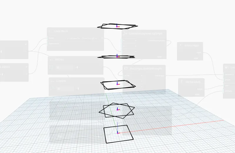
- STEP 9
- CREATE THE SURFACE TO PARAMETRIC STIDIUM
- so that
- go to the libary and type the polysurface by loft as shown below
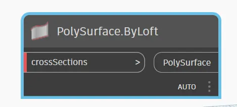
- then connect the geometry to crosssection
- then surface is created shown in results .
- RESULTS :
- CODE BLOCK :
- PARAMETRIC VIEW OF STADIUM :