Creating Conceptual mass in REVIT and Creation of Sinusoidal curve and a Parametric stadium using Dynamo
1.AIM:- To create a set of sinusodial points, create a curve and To create a surface out of the curve.
INTRODUCTION:-
- Dynamo is a visual programming tool that works with Revit.
- Dynamo extends the power of Revit by providing access to the Revit API (Application Programming Interface) in a more accessible manner.
- Rather than typing code, with Dynamo you create programs by manipulating graphic elements called “nodes”.
- It’s an approach to programming better suited for visually oriented types, like architects, designers, and engineers.
- In Dynamo, each node performs a specific task.
- Nodes have inputs and outputs, the outputs from one node are connected to inputs on another using “wires”.
- The program or “graph” flows from node to node through the network of wires.
- The result is a graphic representation of the steps required to achieve the end design.
PROCEDURE:-
Step:-1
- First we open the revit software, and click on the dynamo option in the manage toolbar.
- After opening the dynamo, double click on the dynamo screen, the code block will be visible, as shown below.
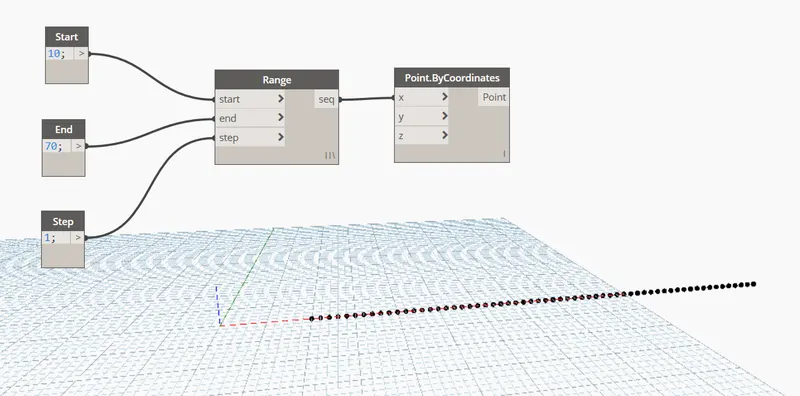
- Create three code box in the dynamo screen, and give the names to the code box individually as start, end and step as shown below.
- Next insert the range and connect start to start, end to end and step to step as shown in the below figure.
- Next we type the point.bycoordinates and connect seq to the x coordinate as shown below.
Step:-2
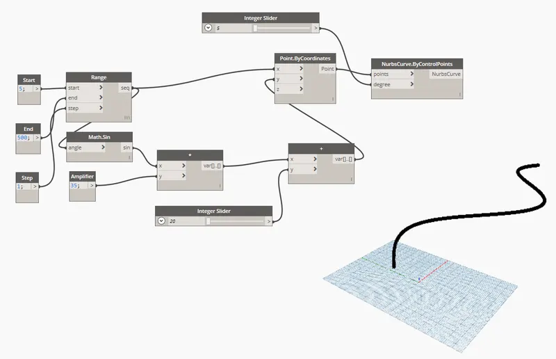
- Next type math.sin and connect the range seq to the angle, as shown below.
- Next type product connect sin to the x.
- Next type code block and rename it as amplifier and connect it to y of the product.
- Next type add and insert it and connect var of product to the x of add, as shown below.
- Next connect var of add to the y of the point bycoordinates.
- Next we type integer slider and give the minimum integer value as 20, and connect it to the y of add.
- Next type nurbscurve coordinate and insert it.
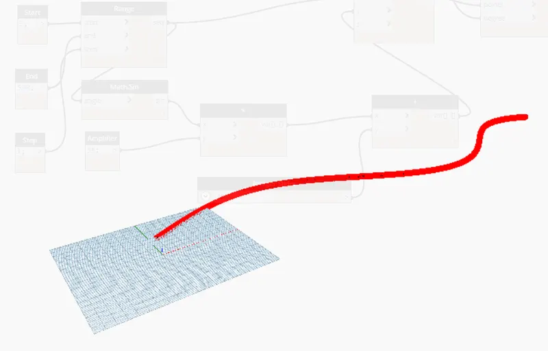
- Next connect point of point by coordinates to the points of nurbscurve coordinates, as shown in the below figure.
- Next again type integer slider and give the minimum integer value as 5, and connect it to the degree of nurbscurve bycontrolpoints, as shown below.
Step:-3
- Next copy the total group and paste it for four times.
- Next type list create and insert, and craete a four items in the list.create.
- Next we connect nurbscurve of all 4 groups to the 4 items in the list.create.
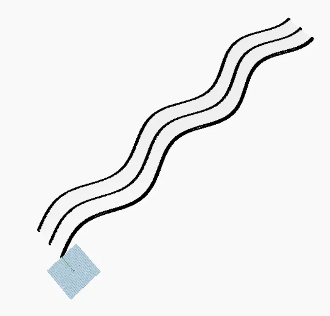
- Next type surface by loft and connect the list to cross section surface.
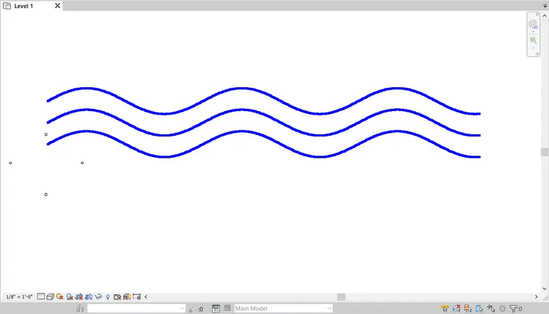
- Finally the surface has been created, as shown in the below figure.
RESULT:-
- Created a set of sinusodial points.
- Created a sinusodial curve.
- Created a surface out of the curve.
2) . AIM:- To create a conceptual layout of floor plan in dynamo using the tools available in dynamo link.
INTRODUCTION:-
- Dynamo, in simple terms, is a plugin for Revit that enhances your design by giving more functionality to Revit that would otherwise be limited due to the nature of the software.
- To compare, like grasshoper is a plugin for rhino to enhance its modeling abilities, Dynamo is likewise the enhancing plugin for Revit.
- The node based logic environment can target elements within a Revit model and manipulate them as long as Revit's back-end system allows.
PROCEDURE:-
Step:-1
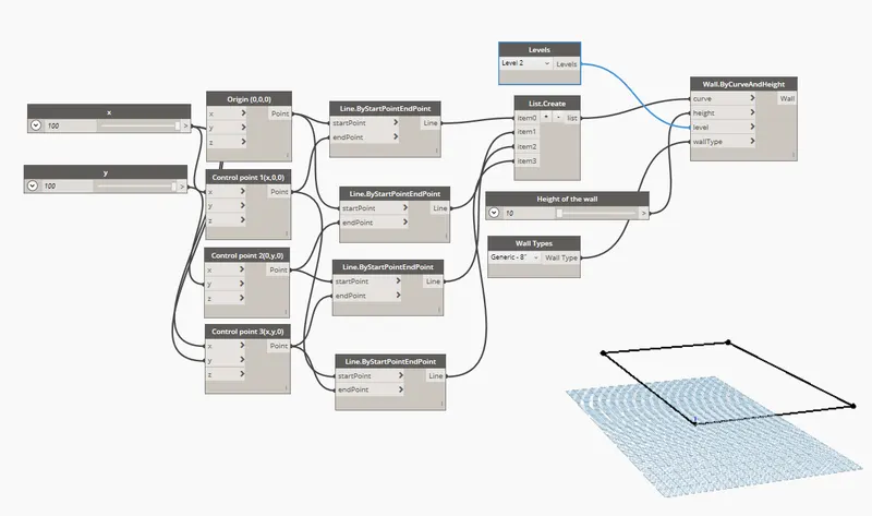
- First we need to enter the two integer sliders and name them as x and y, and give the minimum integer value as 100, as shown below.
- Next type point bycoordinates four times.
- Next connect created integer sliders to the point bycoordinates, as shown in the below figure.
- Next type line.ByStartPointEndPoint and create it four times, as shown below.
- Next connect point bycoordinates to the line.ByStartPointEndPoint, as shown in the below figure.
- Next the remain members are created, as shown below.
- Then the rectangle is created by coordinate points, as shown in the below figure.
Step:-2
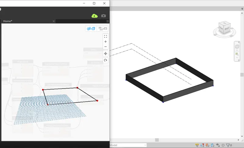
- Next minimize the dynamo screen, and the revit software appears.
- Then the conceptual layout plan is created, as shown below.
Step:-3
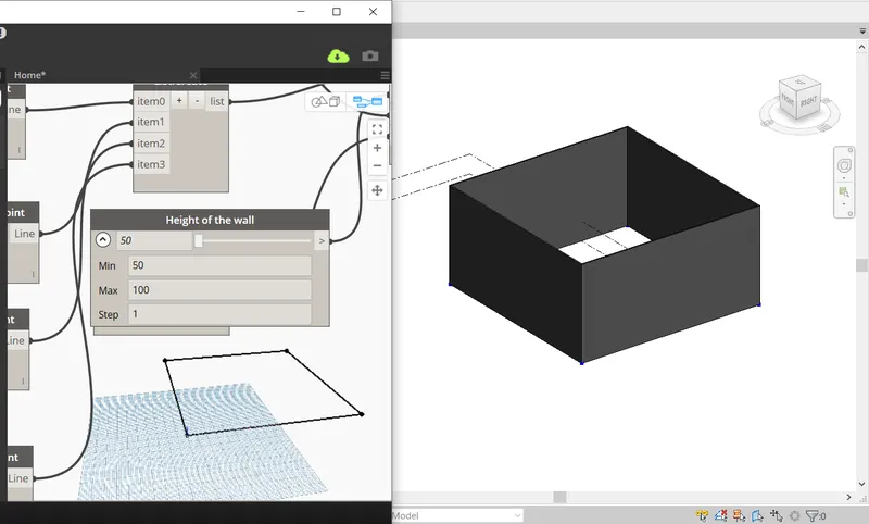
- Next we adjust the height of the wall using the integer slider as shown in the below figure.
- And we can change the minimum and maximum value of the wall height, as shown below.
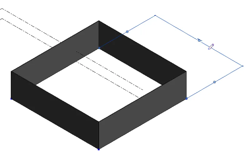
Step:-4
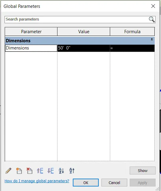
- Next we select the global parameters and give the value as 50', as shown below.
- Then next the length of the wall will be changed, as shown in the below figure.
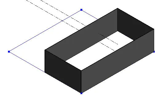
RESULT:-
- Created a conceptual layout of floor plan in dynamo using the tools available in dynamo link.
- The height of the wall and length of the wall has been changed using the sliders.
3) . AIM:- To create an array of model elements in revit using dynamo to vary the properties of model elements by using the slider or code block.
INTRODUCTION:-
- Dynamo is a visual programming tool that works with Revit.
- Dynamo extends the power of Revit by providing access to the Revit API (Application Programming Interface) in a more accessible manner.
- Rather than typing code, with Dynamo you create programs by manipulating graphic elements called “nodes”.
- It’s an approach to programming better suited for visually oriented types, like architects, designers, and engineers.
PROCEDURE:-
Step:-1
- First we have to open the revit software using the architectural template.
- Next create the nine columns, as shown in the below figure.
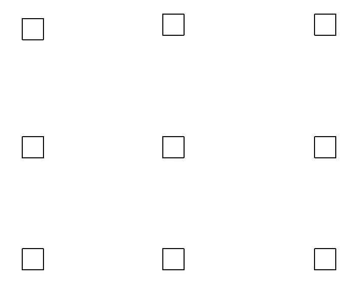
Step:-2
- Next we have to open the dynamo tool, and then the dynamo will be opened, as shown below.
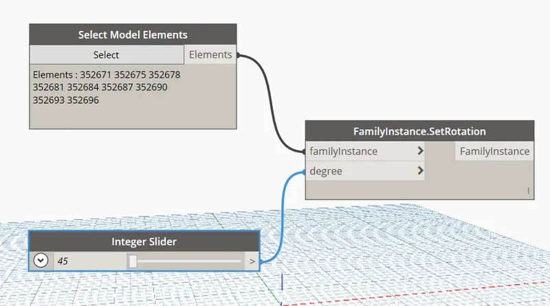
- Next we type the select model elements, integer slider and familyinstance.SetRotation as shown below.
- Next connect elements of select model elements to the familyinstance of familyinstance.SetRotation, as shown below.
- Next connect integer slider to the degree of familyinstance.SetRotation, as shown in the below figure.
Step:-3
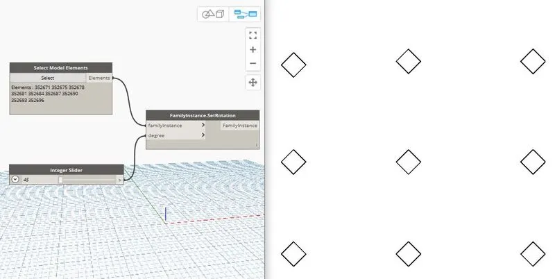
- Next the columns are rotated to the 45 degrees, as shown in the below figure.
RESULT:-
- Created an array of model elements in revit using dynamo to vary the properties of model elements by using the slider or code block.
4) AIM:- To create a conceptual mass in revit and develop a parametric column by dividing the surfaces and,
To apply the concepts similar to used in parametric walkway modelling.
INTRODUCTION:-
- The Conceptual Massing Environment in Revit is a free-form work environment which allows you to explore and iterate many design concepts quickly.
- In this environment, there are no walls, doors, or roofs, only forms and relationships.
- The first time you enter the Massing Environment, it can be a little confusing.
PROCEDURE:-
Step:-1
- First we have to open the revit software, and select the new option in the family.
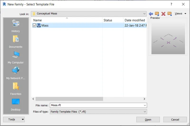
- Next the new family tab will be visible, then select the mass in the conceptual mass folder, as shown in the below figure.
Step:-2
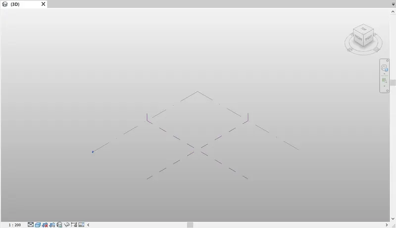
- After selecting the mass from the conceptual mass folder the new screen will be visible, as shown below.
Step:-3
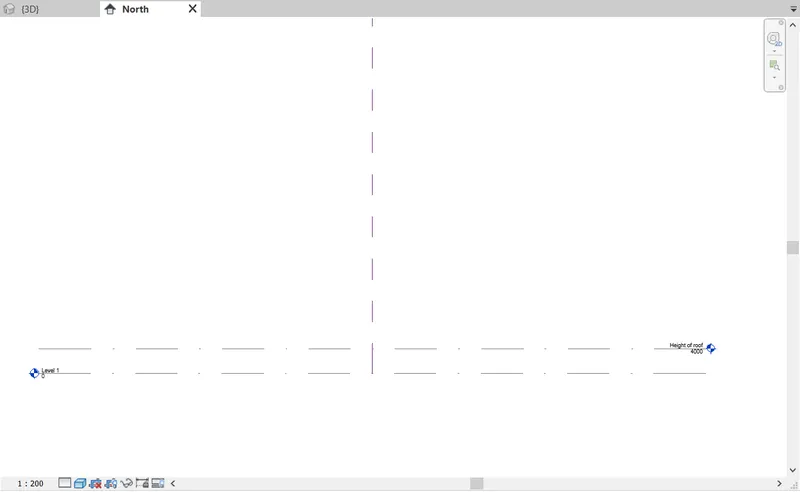
- Next we have to open the north elevation and need to create the level-2, as shown in the below figure.
Step:-4
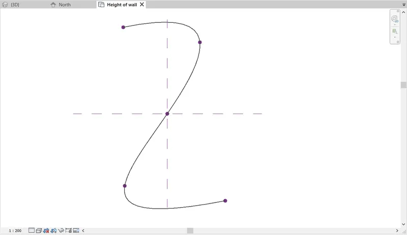
- Next we use the spline tool to draw the walkway curve, as shown in the below figure.
Step:-5
- At the control points we have to create the workplane, and draw the polygon with four sides to the workpalne.
- Similarly create workpalne at the contrl points and draw the polygon with four sides in different angles, as shown below.
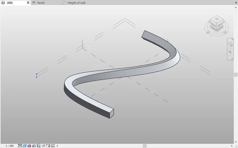
- Next we select the curve line, control points, workplane and polygon. And then create foam, as shown in the below figure.
Step:-6
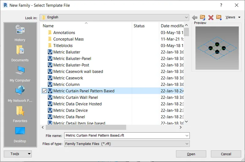
- Next we open the new family, and select the metric curtain panel patern based, as shown in the below figure.
Step:-7
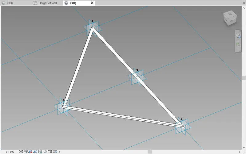
- Next we select the triangle bent pattern, as shown in the figure.
- Next we create the plane at the midpoint and also place the circle at the midpoint with diameter of 2".
- Then the triangle bent pattern was created, and then click on the "load into project" option.
- Then the triangle bent pattern was loaded into the project.
Step:-8
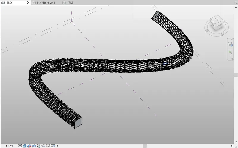
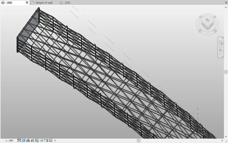
- Next we apply the triangle bent pattern to the parametric column, as shown in the below figure.
RESULT:-
- Created a conceptual mass in revit and developed a parametric column by dividing the surfaces and also applied the concepts similar to used in parametric walkway modelling.
5) AIM:- To draw a parametric stadium using dynamo.
INTRODUCTION:-
- Dynamo is a visual programming tool that works with Revit.
- Dynamo extends the power of Revit by providing access to the Revit API (Application Programming Interface) in a more accessible manner.
- Rather than typing code, with Dynamo you create programs by manipulating graphic elements called “nodes”.
- It’s an approach to programming better suited for visually oriented types, like architects, designers, and engineers.
- In Dynamo, each node performs a specific task.
PROCEDURE:-
Step:-1
- First we have to open the new file in revit, and open the dynamo.
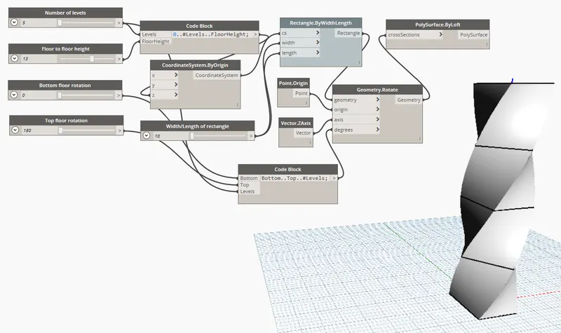
- In the dynamo screen type slider and insert four sliders and rename it.
- Next type points and select points by coordinate to create floor.
- Next type code block and in that code block type (0..#levels..FloorHeight)
- Next join levels and height, as shown below.
- Next type coordinate system by origin and join the code block to it in z.
- Next type code block and in that code block type (bottom..top..#levels)
- Next join the bottom rotation and top rotation and number of levels.
- Next type rectanglebywidth, and type slider and rename it as width/length of rectangle.
- Next join the coordinatesystem to cs.
- Next join the slider to width and length.
- Next type rotate and insert geometry rotate.
- Next type origin and insert point origin.
- Next we have to type z axis & insert it.
- Next join the rectangle to geometry point to origin and degrees to code book(bottom..top..#Levels).
- Next type polysurface by loft and insert it.
- Next join geometry to the cross-section.
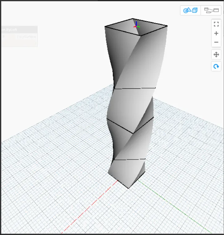
- Therefore, the parametric stadium has been developed, as shown in the below figure.
Step:-2
- Next we hide the total group and then we can see the parametric stadium clearly.
- The parametric stadium has been created successfully, as shown in the below figure.
RESULT:-
- The parametric stadium has been created successfully using dynamo.