Creating Bar Bending schedule, Different Door types, and Creation of standard drawing templates using AutoCad
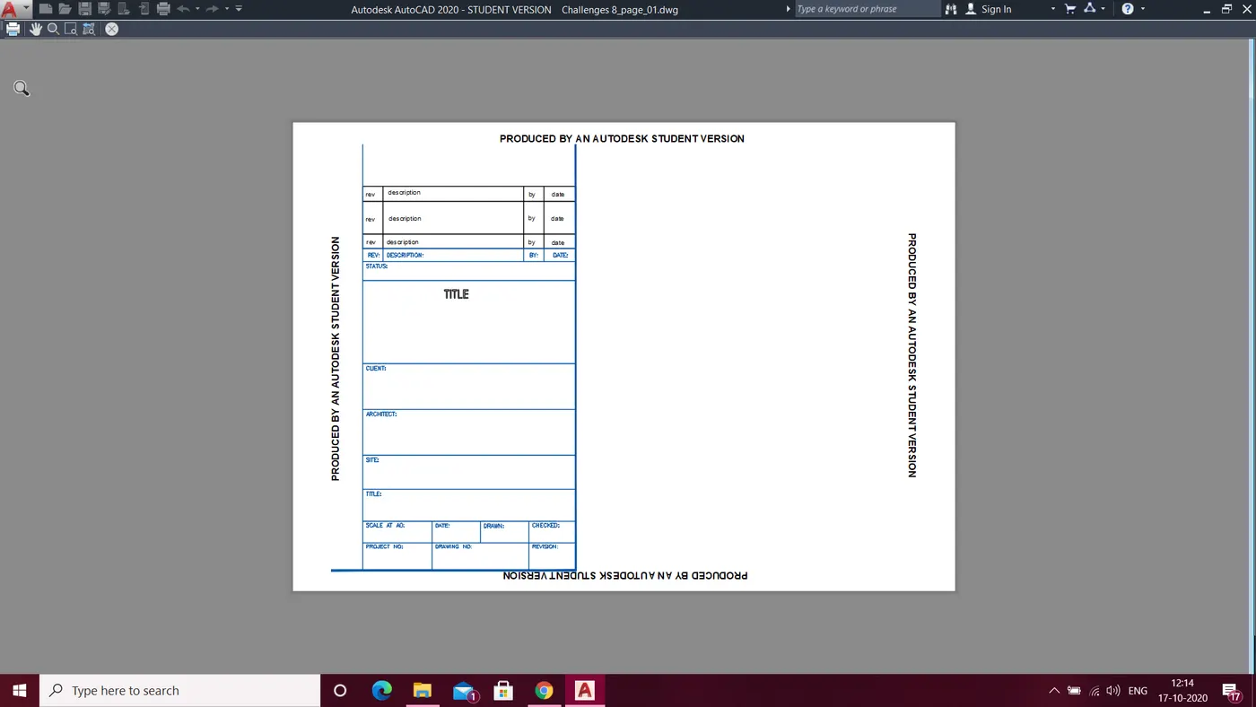
1. Open the autocad
2. Type L in command prompt and specify the first point
3. draw the table as shown in the figure with ortho on
4. select the single line text and change the font to aerial as i have used here
5. type all the text as required
6. right click on the text aand go to properties and change the color to blue as spcified
7. right click on the line and go to properties and change the color to blue as specified
8. Select the complete object and type bl in command prompt and block dialoge box appears
9. select the base point or specify on screen
10. select the object enter
11. Rename it as custom1_titleblock under name and enter
12. It is saved as block
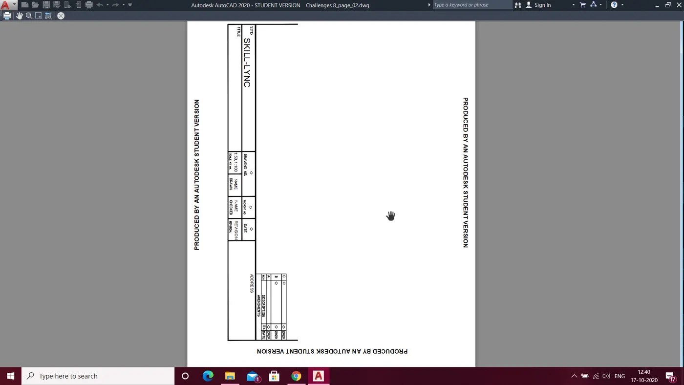
1. Open the autocad
2. Type L in command prompt and specify the first point
3. draw the table as shown in the figure with ortho on
4. select the single line text and change the font to aerial as i have used here and .txth also for the title
5. type all the text as required
6. Select the complete object and type bl in command prompt and block dialoge box appears
7. select the base point or specify on screen
8. select the object enter
9. rename the block as custom2_titleblock under anme and enter
10. It is saved as a block
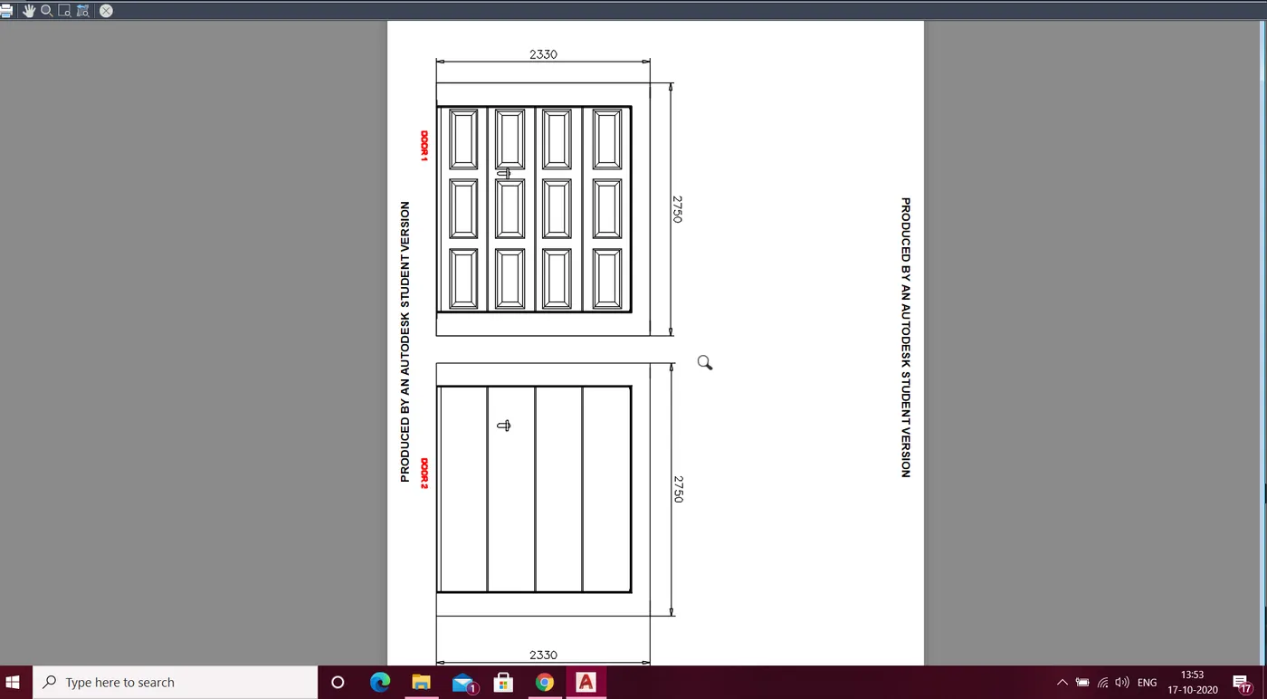
1. Open the autocad
2. Type UN in command prompt and select the units
3. Type Limits and specify lower and upper points z enter a enter
4. Type L in command prompt and specify the first point
5. Type @2330<0
6.Type @2750<90
7. Type @2330<180
8. Type @2750<270
9. Type offset and specify 776.66 and do the offset (horizontally)
10. Type L in command prompt nd specify the first point
11. Type @700<0
12. Type @900<90
13. Type @700<180
14. Type @900<270
15. Type offset and specify 10 and do the offset from all four side
16. trim the extra lines
17. Type offset and specify 20 and do the offset from all side
18. join the lines and one design is ready
19. Type copy in command prompt and copy the entire frame and pste all the places whereever needed as per the drawing
20. Draw the handle as shown in figure
21. Extend the lines from all the outer and inner lines
22. Draw the horizontal line and trim all the other lines
23. Copy the handle and paste it in the second drawing
24. Drawing is obtained as per the given dimension and standard in the question.
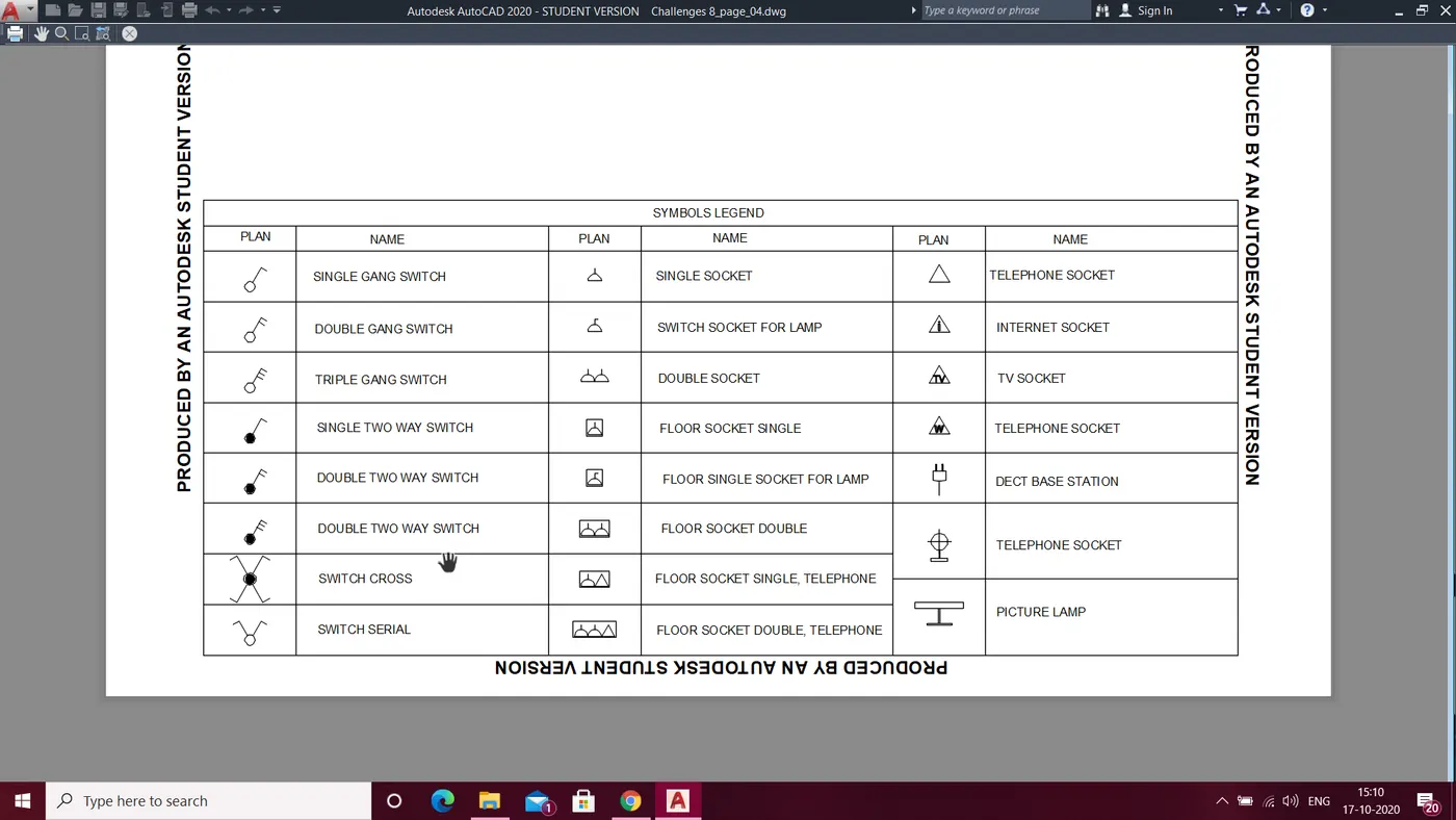
1. Create a rectangle and draw all the rows and columns
2. Draw the figures with the help of line , circle command
3. Type BL in the command prompt
4. Select the object and pick a point
5. Name the block in which you have to represent (title )
6. Block is created
7. In the home bar tap insert and then select the block which you have to insert
8. In the Insert tab there is an option field select object in field name
9. Select the object and then select name
10. In preview select First capital or anyone which is desired
11. Paste it in the legend
12. Do this for all the blocks
13. Legend is created
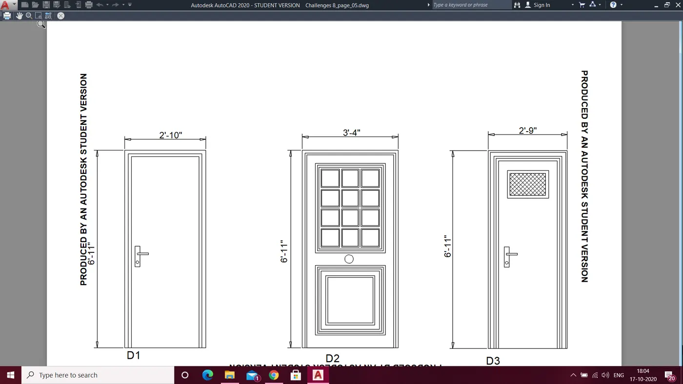
1. Open autocad
2. Type UN in the command prompt and select engineering and precision to 0'-0"
3. Type limits and specify the lower and upper limits
4. z enter a enter
5. Type L in the command prompt and specify the first point
6. Type @2'10"<0
7. Type @6'11"<90
8. Type @2'10"<180
9. Type @6'11"<270
10. Draw the lock handle with the line command and circle
11. first door is obtained
12. Type L in the command prompt and specify the first point
13. Type @3'4"<0
14. Type @6'11"<90
15. Type @3'4"<180
16. Type @6'11"<270
17. Draw rectangle and offset it by 2" 5 times
18. Type offset and specify 4"
19. Draw a circle using circle command
20.Draw a rctangle as preffered size
21. Type offset and specify 2" and do the offset 4 times
22. Type offset and specify 4" and do the offset 2 times vertically and horizontally
23. Trim the extra lines and join the lines
24. Second door is obtained
23. Type L in the command prompt and specify the first point
24. Type @2'9"<0
25. Type @6'11"<90
26. Type @2'9"<180
27. Type @6'11"<270
28. Draw the lock handle with the line command and circle
29. Draw a rectangle and offset it by 2"
30. Hatch the portion by hatch option in ribbon command and third door is obtained
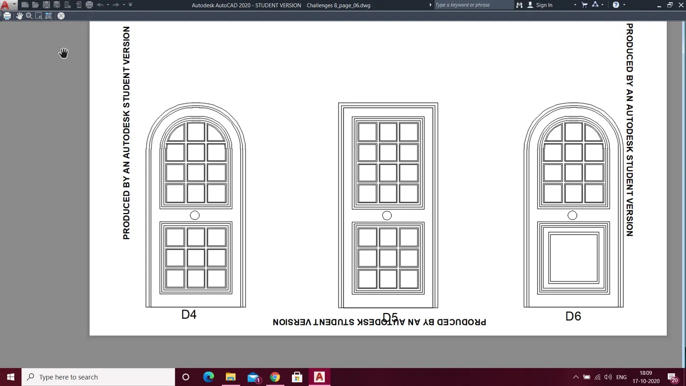
31.Type L in the command prompt and specify the first point
32. Type @2'10"<0
33. Type @6'0"<90
34. Type @2'10"<180
35.Type @6'0"<270
36. Select the point and draw a circle using two end point method
37. Trim the below half circle
38. Type offset and do the offset of 2"
39. Draw rectangle and do the offset of 2" 5 times
40. Type offset and specify 4" and do offset 2 times vertically and horizontally
41. Trim the extra lines and join the lines
42. Type copy and select the object and place at the top and draw semi circle and trim the extra line
43. Draw the offset of semi circle and join the lines
44. Draw a circle at the middle door is obtained D4
45. Type copy and select the entire D4 and paste it and change the name as D6
46. At the lower portion trim off the extra lines and keep the outer lines
47. Door is obtained as i have taken as same dimension of the door
48. For door D5 type co in command prompt and copy the entire D2 and paste it
49. At the lower portion trim or delete all the intersection lines and keep the outer lines
50. Door is obtained as the same dimension as of D2
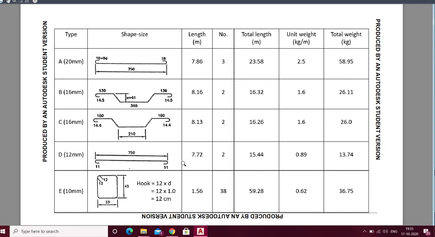
1. open the autocad
2. Type UN and select the units and precision
3. Type limits and specify lower and upper points
4. z enter a enter
5. Choose the line thickness broad and make the design
5. Draw a line of 700mm using line command and by using the fillet draw the hook
6. using dimension get the distance and then type BL and select the object
7. select the base point and then select del and then specify the name and enter
8. Similarly draw all the blocks using this procedure
9. Draw a rectangle table with all the rows and columns
10. Select insert block and select the first block and place it at the desired place
11. Repeat with all the blocks and place them simultaniously
12. Select text command and give all the information and type all the information accordingly
13. Desired Table is obtained as per the question