Creating Architectural and Structural model with 3D rendering using REVIT
1.Setup model for RC building design and based on following parameters for cover.
A.Aim: To setup model for RC building design and based on following parameters for cover.
Tools Required:
- Tekla model
- File Menu
- Settings
- Structural Defaults
Procedure:
- Firstly, open the new file.
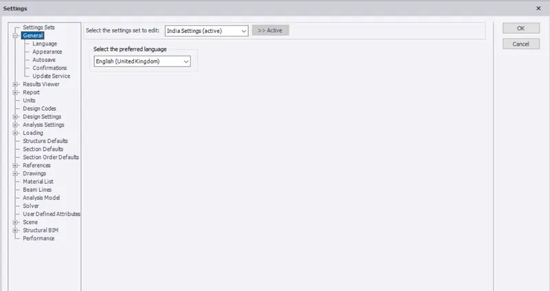
- Now under the file menu select the settings option.
- A dialogue box will appear on the screen.
- Now select the structural defaults and sets all the values as per our requirement.
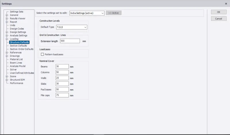
Result:
Hence the parameters for the structural model are set accordingly.
2. Model grids as per the attachment 2,2.1 and 2.2.
A.Aim: To model the grids as per the attachment 2,2.1 and 2.2.
Tools Required:
- Construction Levels
- Girds
- Parallel (quick)
- Properties
Procedure:
- Firstly, open the new file.
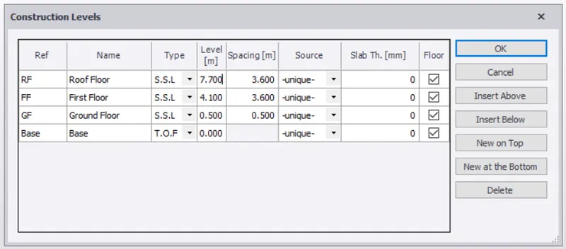
- Now under the structures option select the construction levels and mane them and give the spacing as per the attachments.
- Now click on model tab and select the grid option.
- Now with the help of that option draw a grid line and keeping that as reference draw the remaining grid lines.
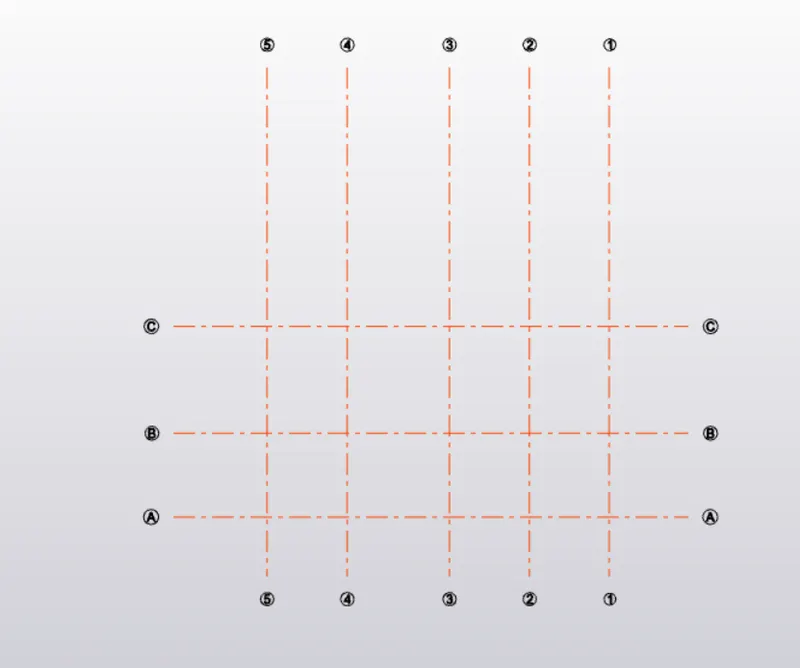
Result:
Hence we were able to create the construction levels along with the model grid lines as per the attachments provided.
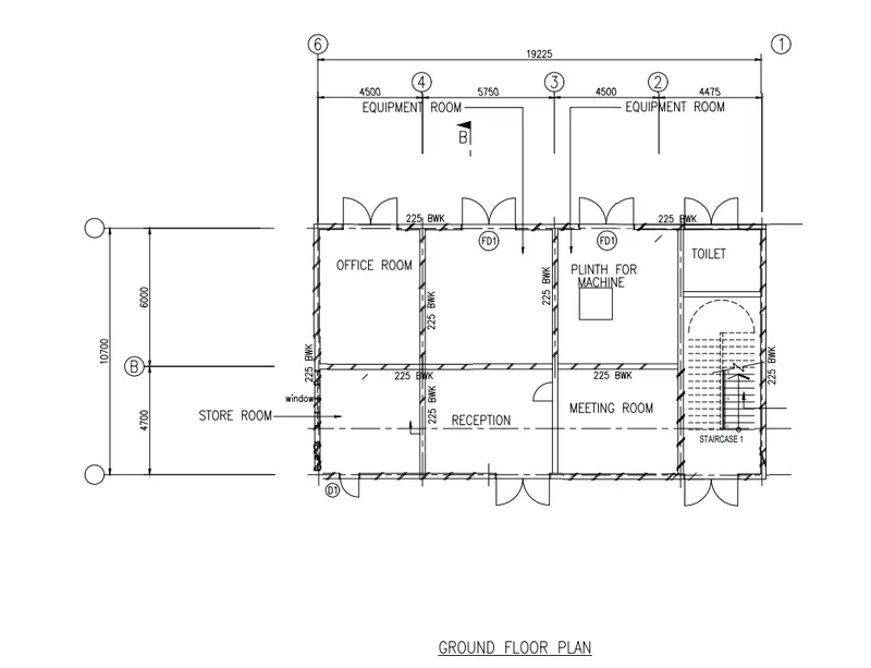
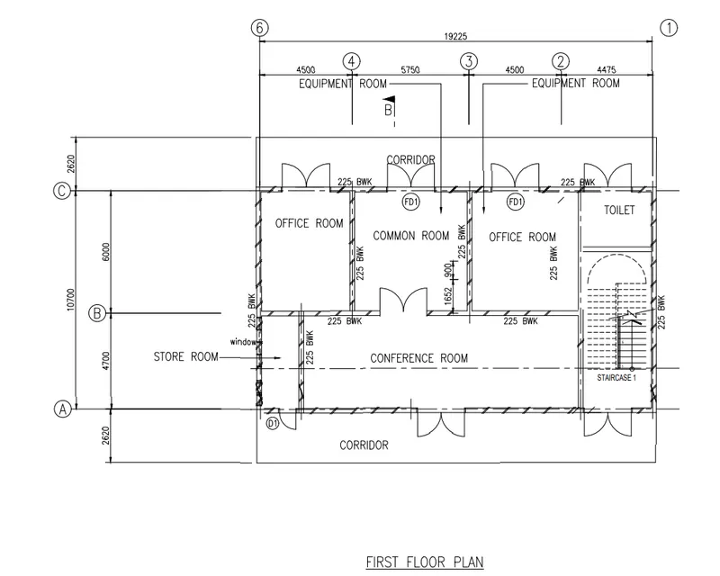
3. Study the layout and write a summary for general arrangement of the structure.
A.Aim: To study the layout and write a summary for general arrangement of the structure.
Tools Required:
- Attachments
- Paint Tool
Procedure:
The drawing interface layer provides for graphic input of an architectural plan. It is a menu-driven drafting system that incorporates the following features.
- Provides a convenient drawing system.
- Does the initial processing necessary to identify and classify the building components in a drawing, producing a representation of the drawing using a frame-based representation.
- Extracts the geometric features and produces a semantic network representation of the drawing; this semantic network representation links together the frame representation of building components.
- The friendly interface is facilitated by access to the underlying knowledge structures about building components. The menu driven system can automatically access the meanings of the symbols that it draws.
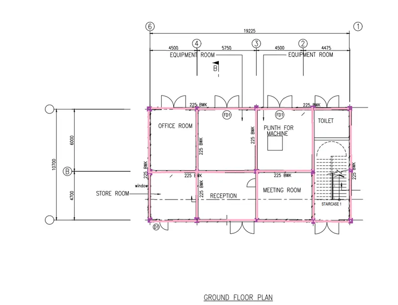
- With the help of paint tool open the attachments there and draw in the file where ever you wanted to place beams.
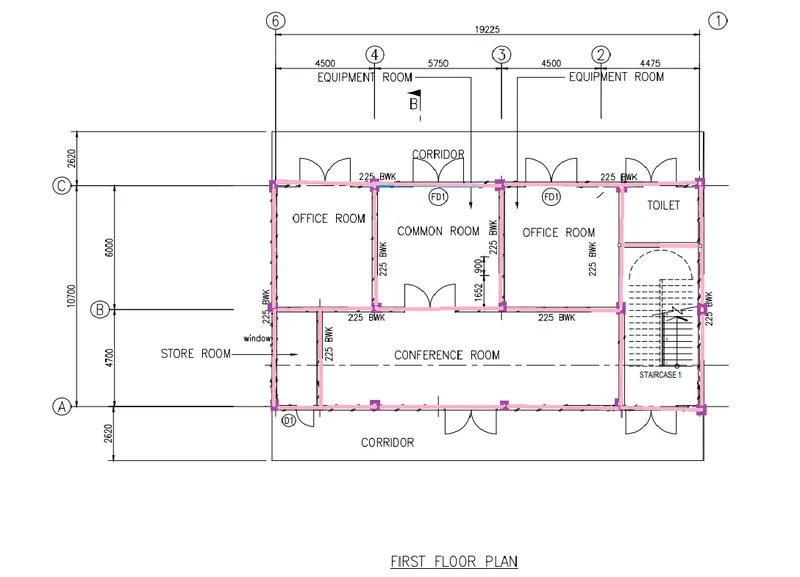
- And draw in the place where ever you wanted to place columns.
Result:
Hence the layout is perfectly studied and in process of execution.
4. Model RC columns, beams and slabs as per your general arrangement.
A. Aim: To model RC columns, beams and slabs as per your general arrangement.
Tools Required:
- Levels
- Manage Properties
- New
- Members
- Concrete Column.
- Concrete Beam
- Slab
- Grids
- RC beams
- RC Columns
- Slab
- Manage Properties
- Properties
Procedure:
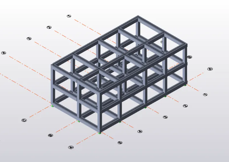
- Open the grids files that you have already created.
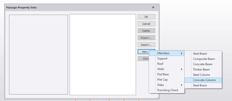
- Now click on the levels option which is present at the right side of the display and you will be directed to a new dialogue box where in you have to assign the levels accordingly as show in the picture give below with its respective values, later click ok.
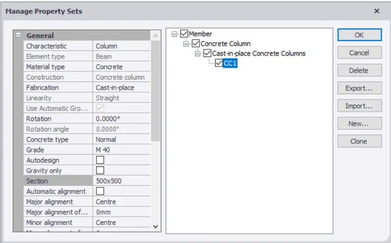
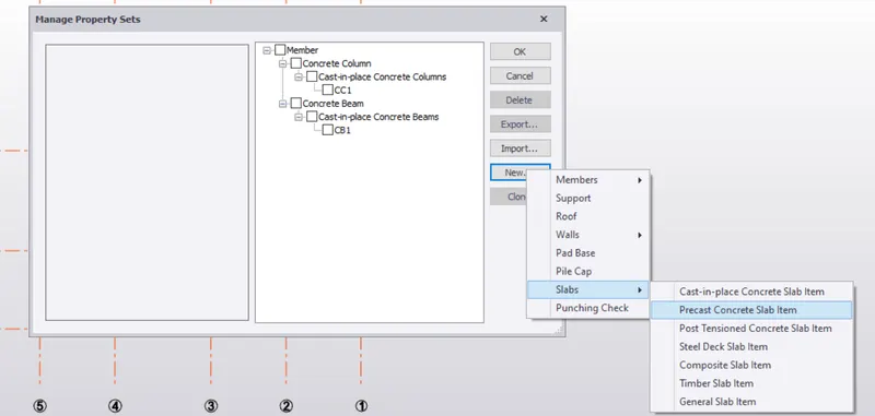
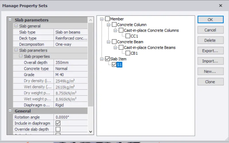
- Now select the manage properties option and again you will be directed to a new dialogue box where in you have to select and create a new member of concrete column naming it as CC1 assign the values as per our requirement in the general tab.
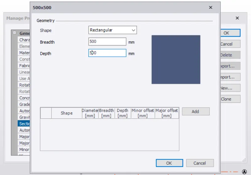
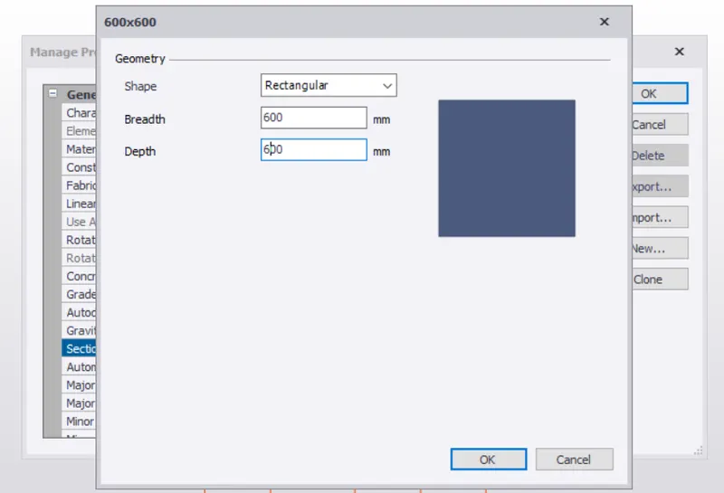
- Now you can also edit the other values like the length and width also the shape of the column and many more.
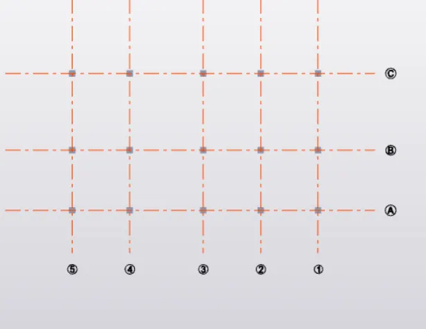
- After all the settings are done click ok.
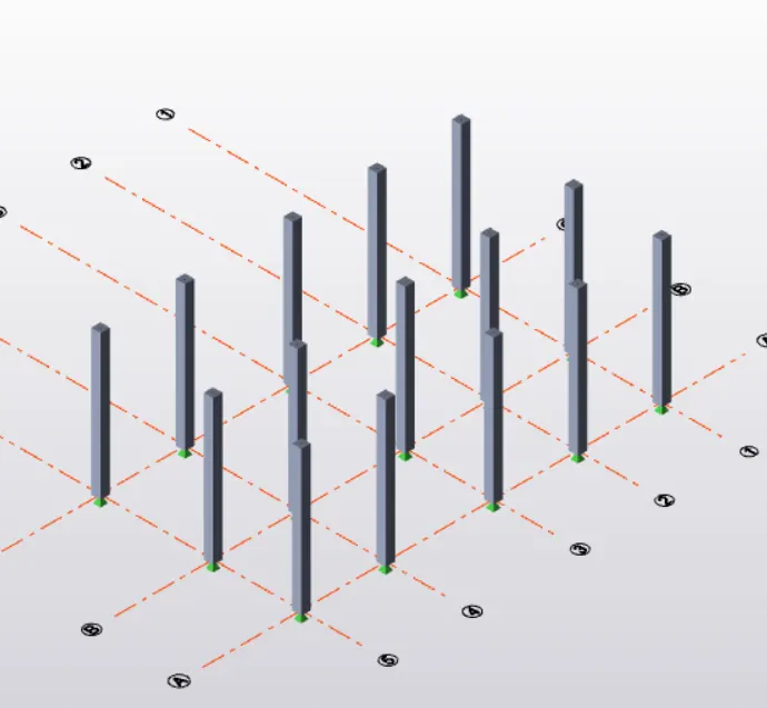
- Now you can see the grids file that is open on your project workspace now select on column that is present under the model tab.
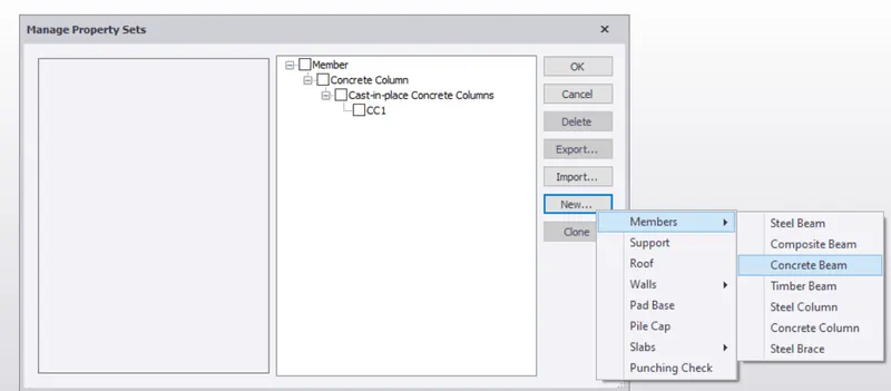
- Now you can see that there are properties of the column displayed at the properties bar although you have modified the properties but its good to go for a check for you to feel everything is according to our requirement.
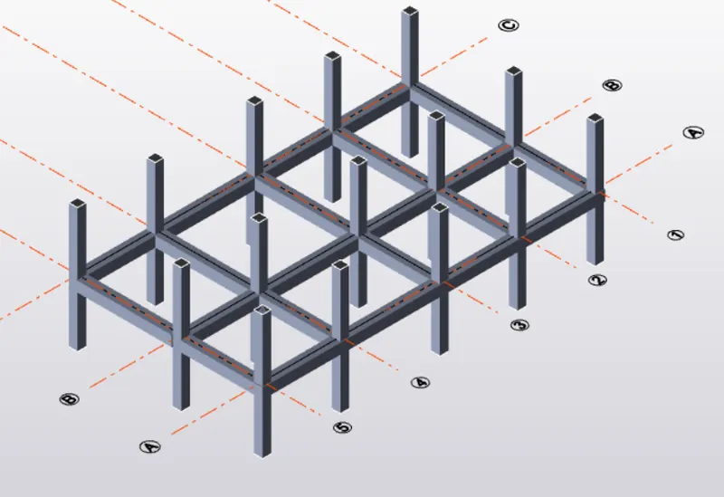
- Now according to the attachments place the columns in their respective places.
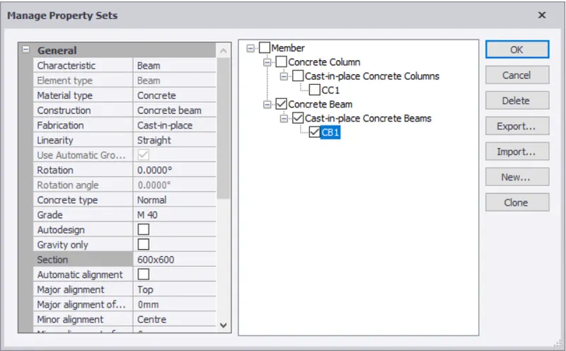
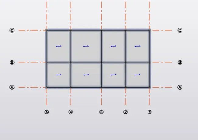
- In the same way following the above procedure for the concrete beams and slab as well.
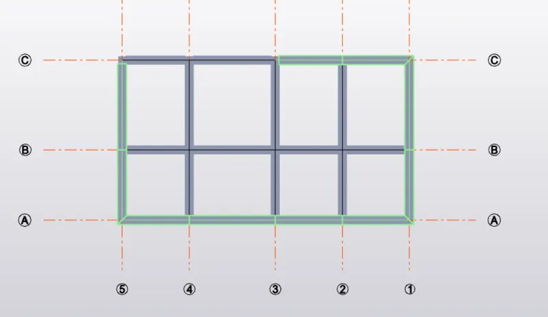
- By naming the concrete beam as CB1 and slab as S1.
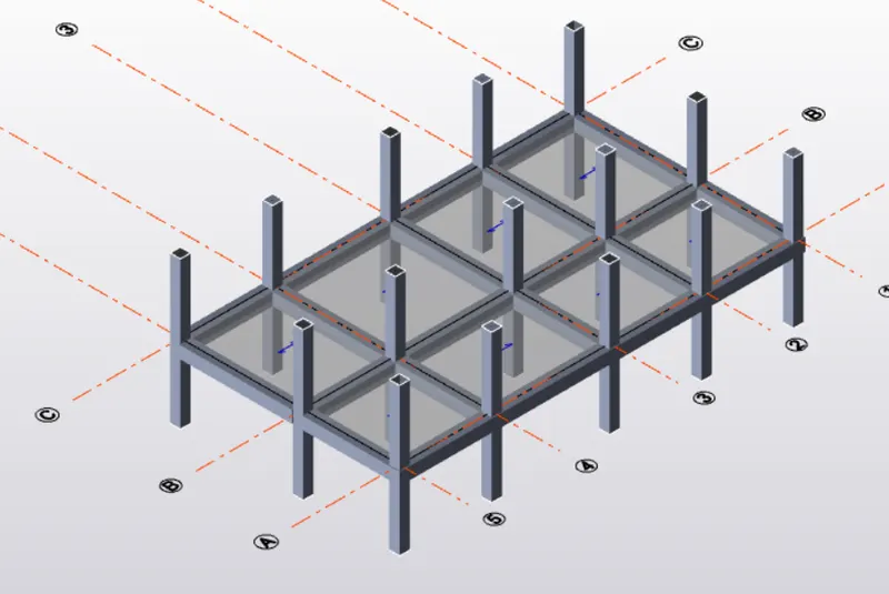
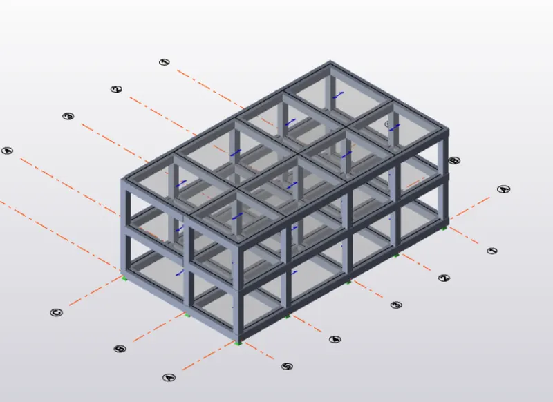
Result:
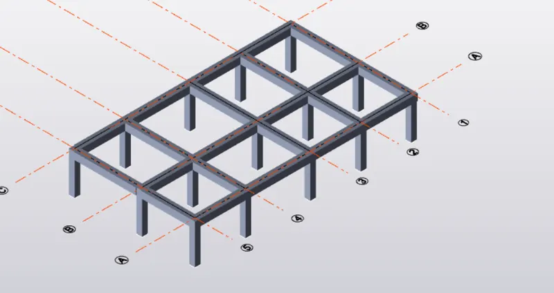
Hence by following the above procedure we can model RC columns, beams and slabs as per our general arrangement.