Creating Architectural and Structural model with 3D rendering using REVIT
- CREATE A RCHICTUCTURAL AND STRUCTURAL MODEL WITH 3D RENDERING USING REVIT :
- QUESTION : 1
- Select the type of structure you want to build from one of the three below:
a Multi-Unit Residential Apartment
b. Office Buildings
c. School - ANSWER :
- for the project i have selected multi- unit residential apartment
- QUESTION : 2
- Assume reasonable assumptions for geographic and location details for your project modeling. Based on assumptions and type of structure selected identify the modeling requirements from NBC
- ANSWER :
- My building is constructed in plan area or flat area
- location :
- the building is constructed in commercial area , DHULE MAHARASHTRA , INDIA
- QUESTION : 3
- Using the structural model, include the following components based on the type of structure selected
a. Foundation – Isolated / Wall/Matt Foundation
b. Columns
c. Beams Connected to Columns
d. Roof Framing/ Truss
e. Floor / Decks
f. Floor Openings for Elevators and Stairs - ANSWER :
- AIM :
- TO DRAW THE STRUCTURAL MODEL OF MULTI STORY APPERTMENT
- PROCEDURE :
- STEP 1
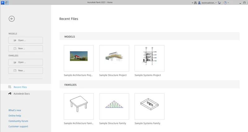
- start the revit 2023 software by double click on them
- then homepage of revit is open as shown below
- STEP 2
- then click on NEW option from that homepage
- then new dialogbox is open
- from that dialog box click on dropdown
- selct the templet as ARCHICTURAL TEMPLET
- as shown below
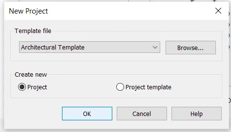
- then click on OK
- STEP 3
- then go to the file tab
- click on save the project
- give the file name as STRUCTURAL MULTI STORY APPERTMENT
- Ans save it
- STEP 4
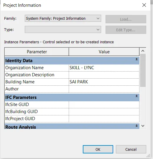
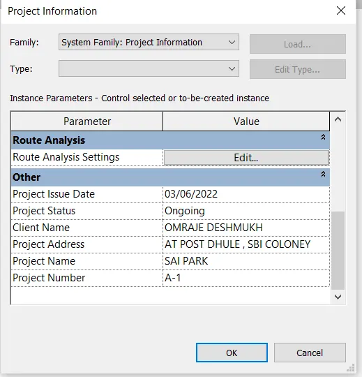
- go to the MANAGE TAB
- fromthat manage tab click on project information and fill then information as shown below
- STEP 5
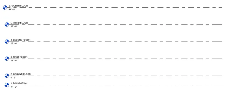
- from archictural tab
- click on datam tab
- click on level
- and mark the level as shown below
- STEP 5
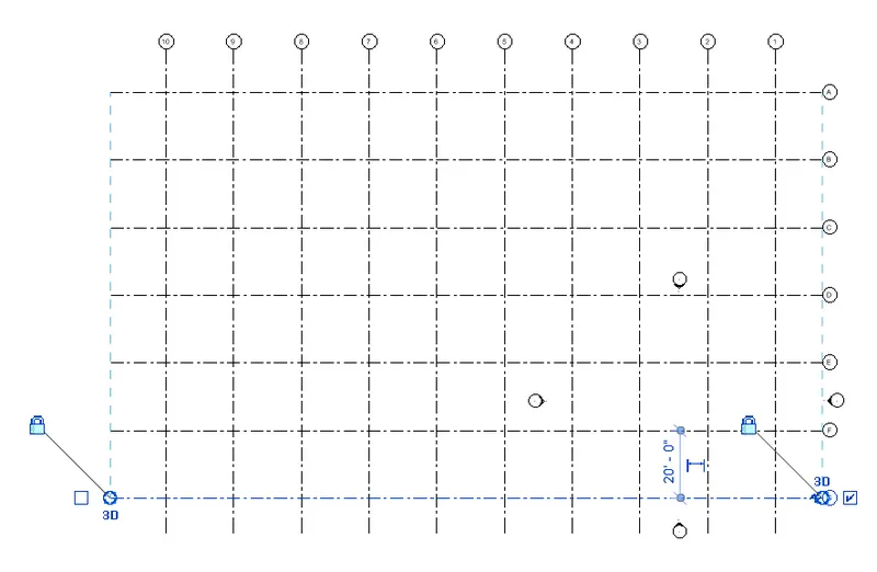
- go to the properties broswer
- go to the structural plan
- from that click on FOUNDATION PLAN
- then go to the datam option
- from that click on grid option
- and mark the grid
- and rename it as horizontal grip as A,B,C etc AND Vertical grid as 1,2,3,4 ETC as shown below
- STEP 6
- go to the structural tab
- click on ISOLATED FOOTING
- footing size-1800x1200x450
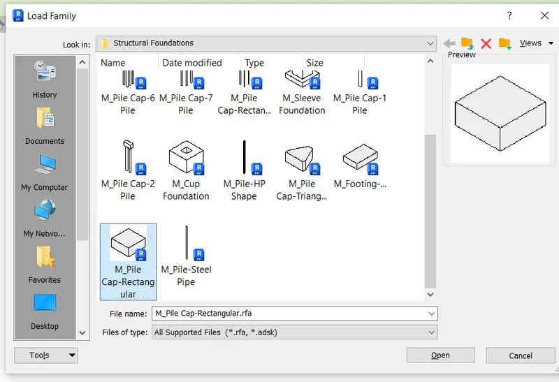
- then go to the load family
- double click on structure
- and load the cap as shwn below
- then click on ON GRID option
- select the grid
- and click on finished
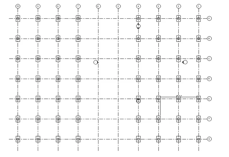
- then same way go for cloumn
- go to the structural tab
- select the archictural column
- column size 600x600
- click on on grid option
- and mark a column
- select the base level as FOUNDATION LEVEL
- and top level as FOURTH LEVEL
- click on apply
- STEP 7
- go to the properties broswer
- click on GROUND FLOOR LEVEL
- then go to the structural tab
- click on beam option
- select the comcrete beam having size is 600x600
- mark the beam as shown below
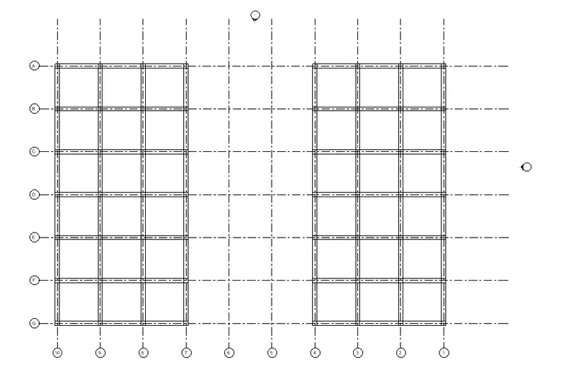
- by using same procedure provide the beam in all floor
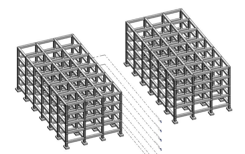
- RESULTS :
- QUESTION : 4
- Using the architectural model, include the following components based on the type of structure selected
a. Wall Layout with appropriate material and finishing
b. Exterior façade with fancy finish
c. Interior partition walls to size rooms
d. Components to add details to a room ( Desk, Chair, Lighting, Plumbing fixtures)
e. Add components such as stairs Elevators
f. Have at-least one side of the building with curtain walls and glass panels
g. Include interior and exterior lighting fixtures
h. Place proper topographic components from outside ( Trees, Parking, Plants) to add details to the model - ANSWER :
- AIM :
- TO DRAW THE ARCHICTURAL MODEL OF MULTI STORY APPERTMENT
- PROCEDURE :
- STEP 1
- go to the properties broswer
- click on ground floor level
- then go to the archicture tab
- click on wall
- select the wall
- click on duplicate
- rename it as BASIC 9" WALL as shown below
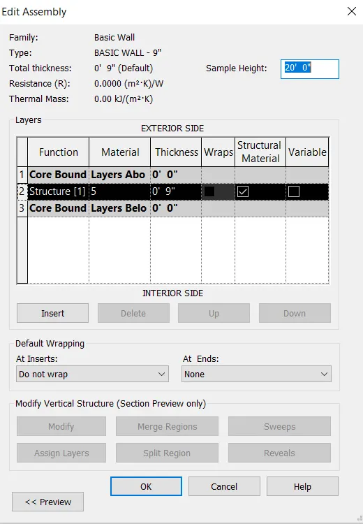
- click ok and mark the wall
- then go to the properties broswer
- give the base level as ground floor level
- and top level as forth floor leve
- and click on appy
- in this way provide all walles to the flat
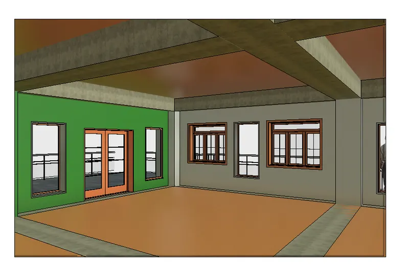
- WINDOW AND DOOR
- then click on archictural tab
- click on door
- then go to the load faimy
- select the door
- and placed it as shown in floor plan
- then same way provide the window
- 3d view of door and window shown below
- 3D view of doors and window :
- provide floor :
- go to the ground floor plan
- then go to the archictural tab
- click on floor option
- then select the line option to draw the floor
- as shown below
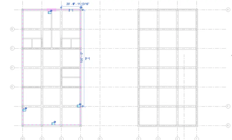
- and mark the floor
- then selct the floor
- and copy it
- click on past option
- selct level where we have to provide the floor
- and past it
- then go to the ground floor plan
- go to the insert tab
- click on load family
- and insert it as shown below
- ground floor plan shown below
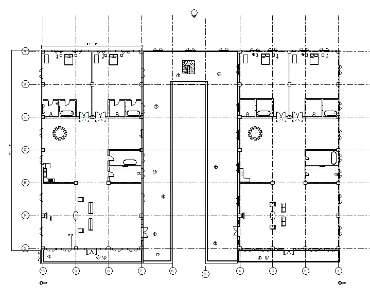
- select the all inserted element
- click on copy
- then click on past option
- slect the level and past it
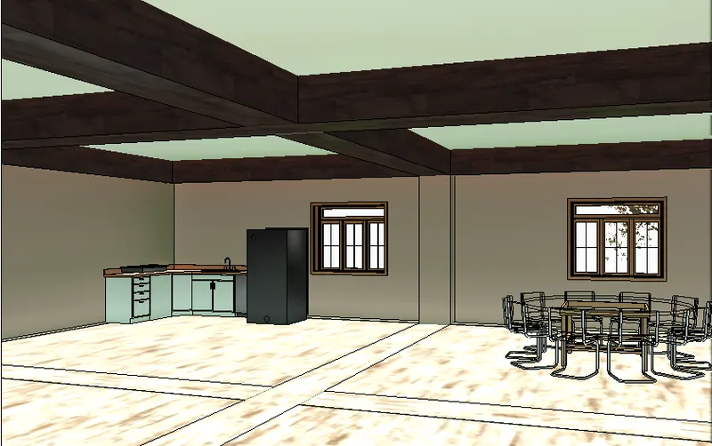
- KITCHEN :
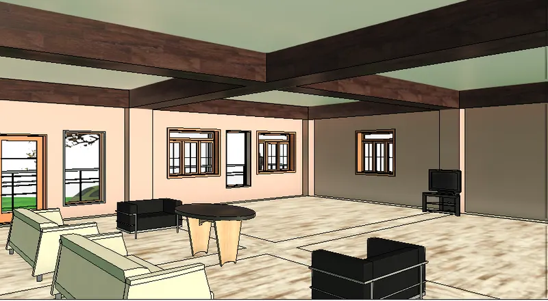
- LIVING ROOM :
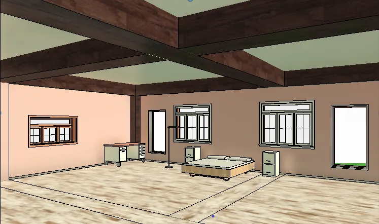
- BED ROOM :
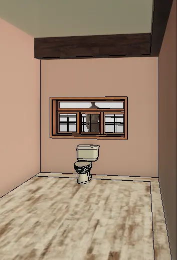
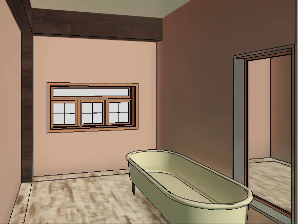
- TOILET AND BATH :
- BALCONEY :
- go to the properties broswer
- click on ground floor plan
- then go to the archictural tab
- click on floor opton
- selct the rectangle option to draw the floor
- and then click on finshed
- then select the floor
- and copy it
- then click on past option
- select the anighed to level
- selct the level where balconey we want
- and past it
- then click provide the relling to the balconey
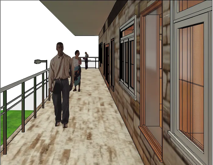
- 3D VIEW OF BALCONEY :
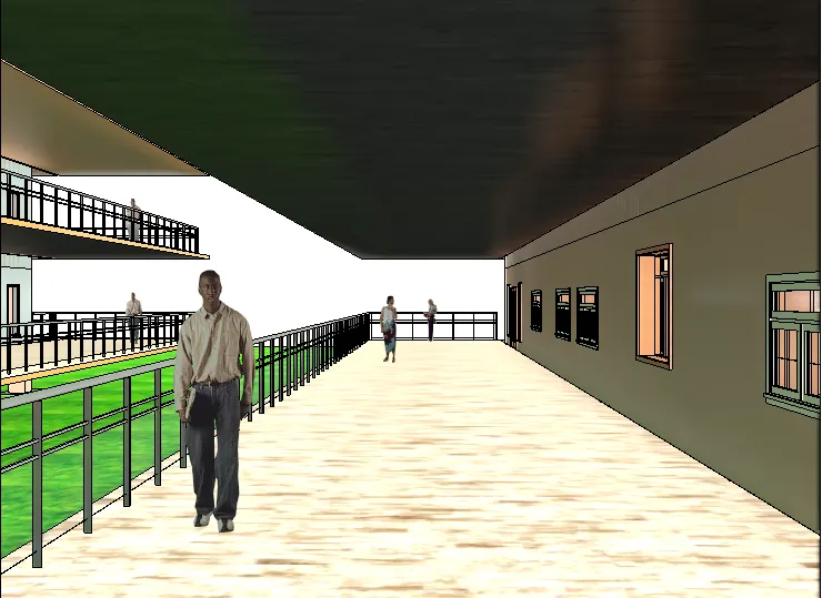
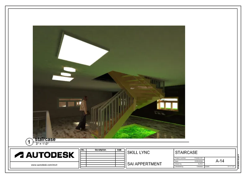
- STAIRCASE
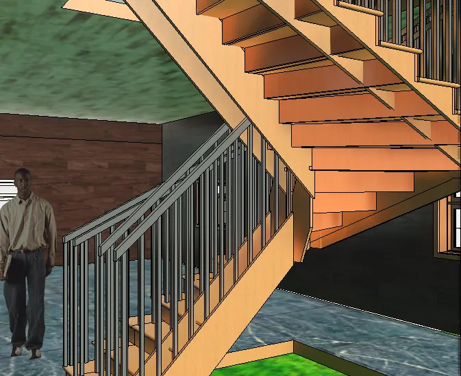
- go to the properties brower
- click on foundation
- then go to the archicture tab
- click on stair option
- selct the U shape staircase
- and place the stair
- then select the stair
- give the base constent as foundation level
- and top constant as fouth level
- then click on apply
- then provide the opening for staircase
- then again go to the archictural tab
- click on shaft
- selct the rectangle option for provide the opening
- give the base level as ground floor level
- and top level is fourth floor level
- click on apply
- 3D VIEW OF STAIRCASE :
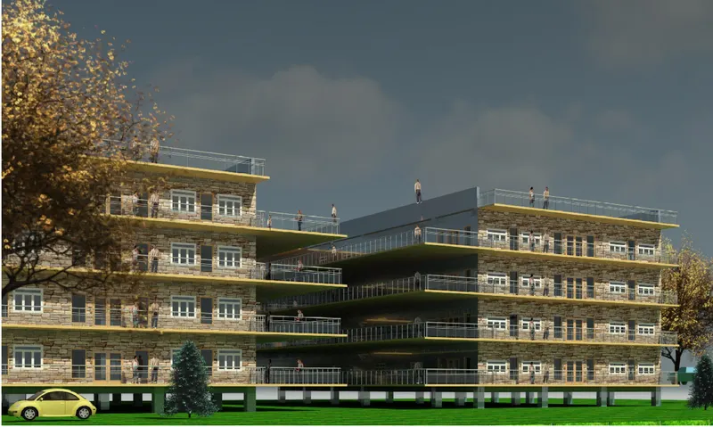
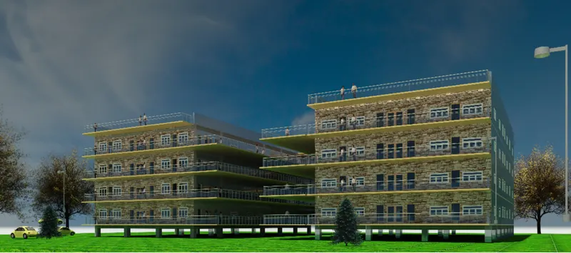
- RESULTS :
- QUESTION : 5
- ) Provide a set of drawings in an architectural and structural model to list the following details with categories and appropriate sheet templates included
a. Floor Plans with Annotations
b. Elevations
c. Sections - ANSWER :
- PROCEDURE :
- STEP 1
- start the revit 2023 software
- then homepage of revit is open as shown below
- STEP 2
- then click on OPEN option from the homepage
- then selct the file and open it
- then go to the properties broswer
- click on ground floor plan
- then go to the view tab
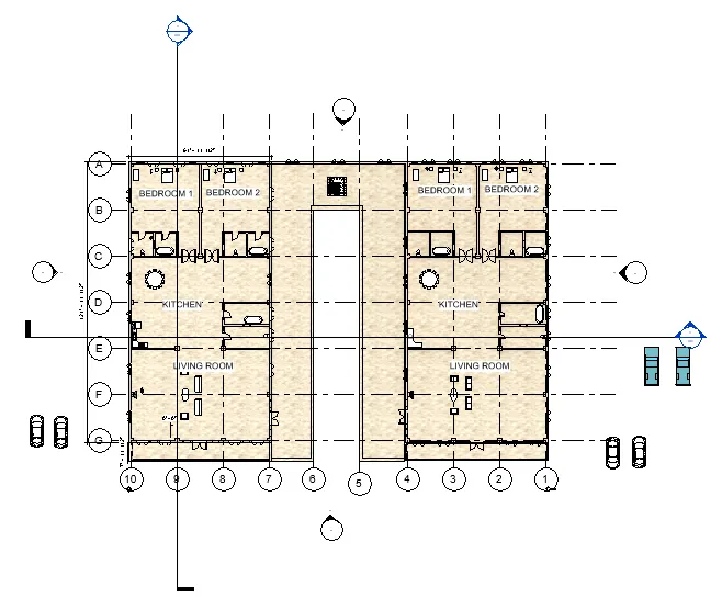
- click on section
- thne provide the section line as shown below
- then go to the properties broswer
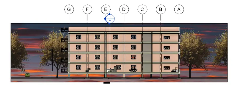
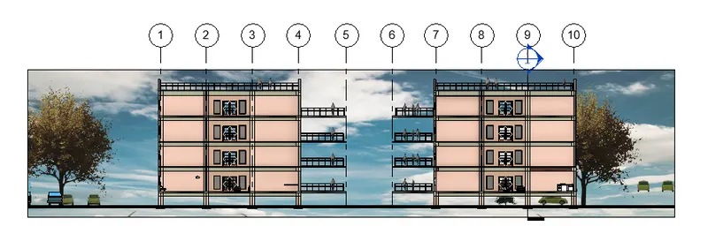
- click on section view
- SECTION VIEW1 :
- SECTION VIEW 2 :
- STEP 3
- then go to the insert tab
- click on load family
- then click on titlebox
- select the requried sheet
- thne click on open
- go to the properties broswer
- then click on sheet
- Then go to the properties broswer
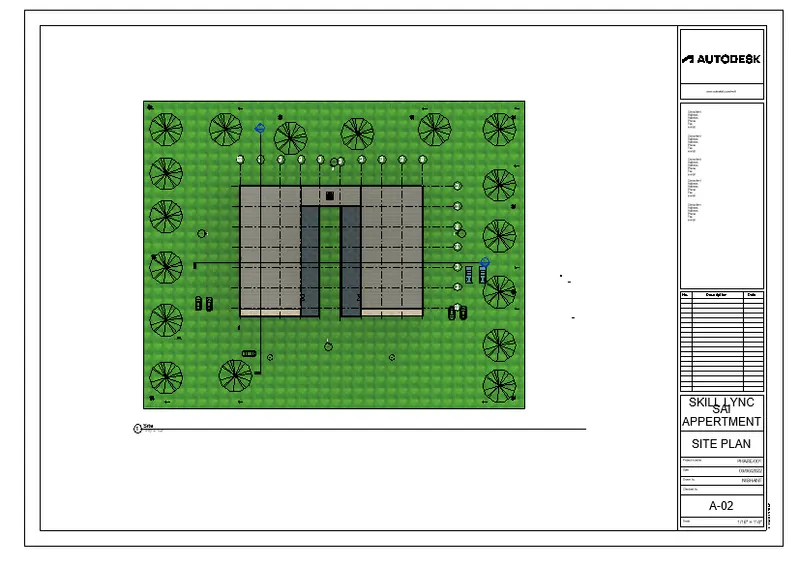
- go to the site plan
- drag it and place it into the sheet with proper scale shown below
- SITE PLAN :
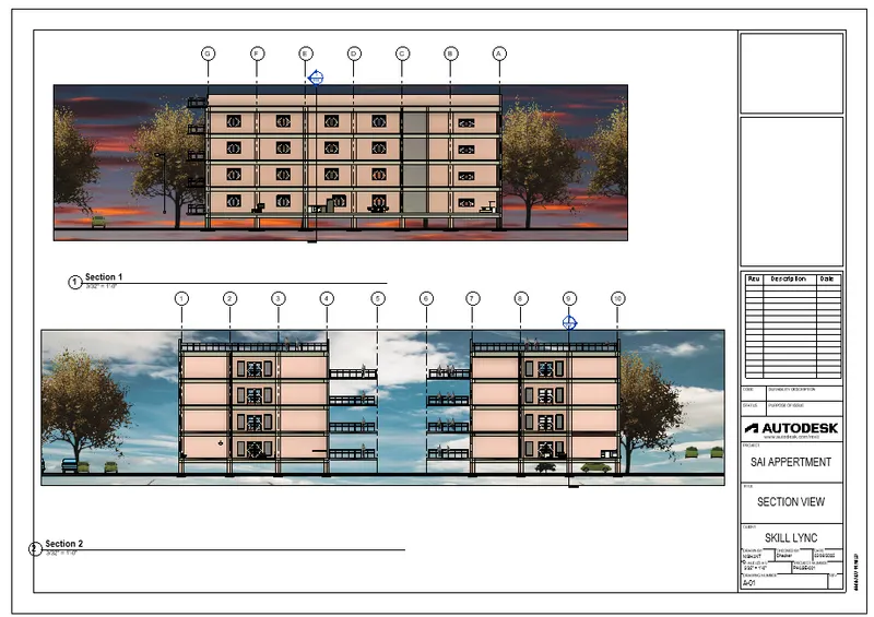
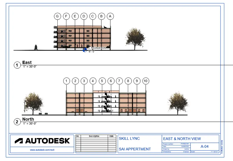
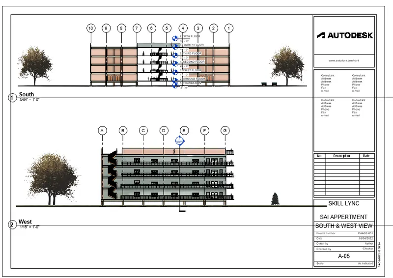
- In this way placed all views in sheet shown below
- SECTION VIEW :
- EAST AND NORTH VIEW :
- SOUTH AND WEST VIEW :
- QUESTION : 6
- Using the Rendering settings, Render images of the 3D model produced and include the rendered images to the drawing sheets
a. Rendering from interior rooms
b. Rendering from out showing topographic features
c. Rendering through structural framing - ANSWER :
- PROCEDURE :
- STEP 1
- Start the revit software
- then homepage of revit is open as shown below
- STEP 2
- then click on OPEN option from that homepage
- select the file and open it
- STEP 3
- For render go to the view tab click on render
- do proper setting shown below
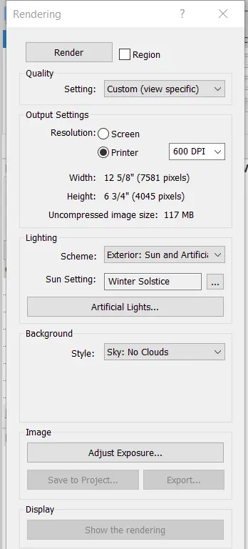
- Then do to same setting for all view
- and render the it
- and save the image
- STEP 4
- then go to insert tab
- click load family
- then click on titleblocks
- select the sheet
- and open it
- then go to the properties broswer
- click on sheet
- then right click on sheet
- and rename it
- then go to the properties broswer
- go to the rendering
- drag the image and placed it into the sheet with proper scale shown in results
- RESULTS :
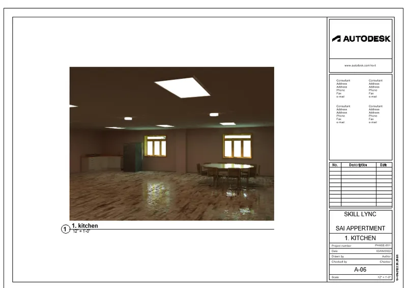
- KITCHEN
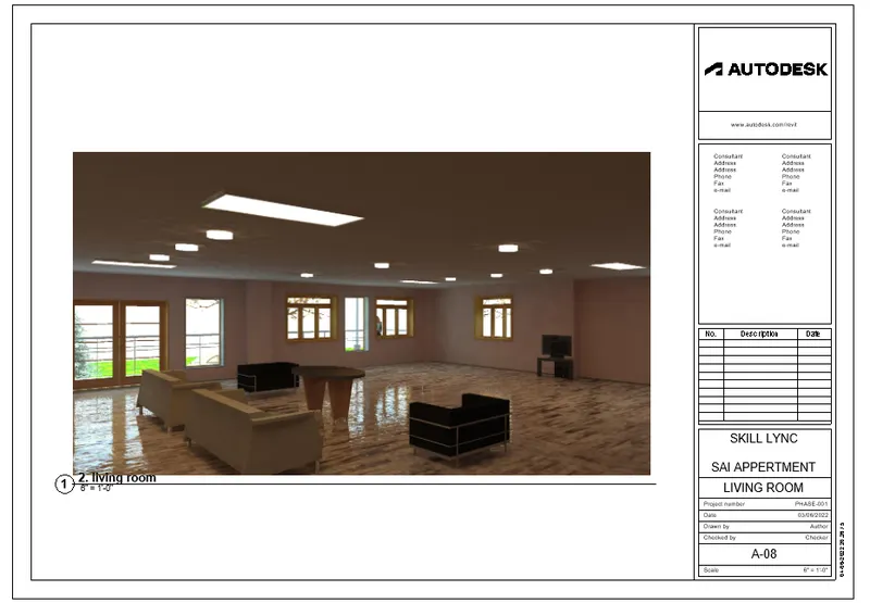
- LIVIGN ROOM :
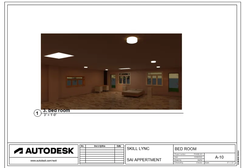
- BED ROOM :
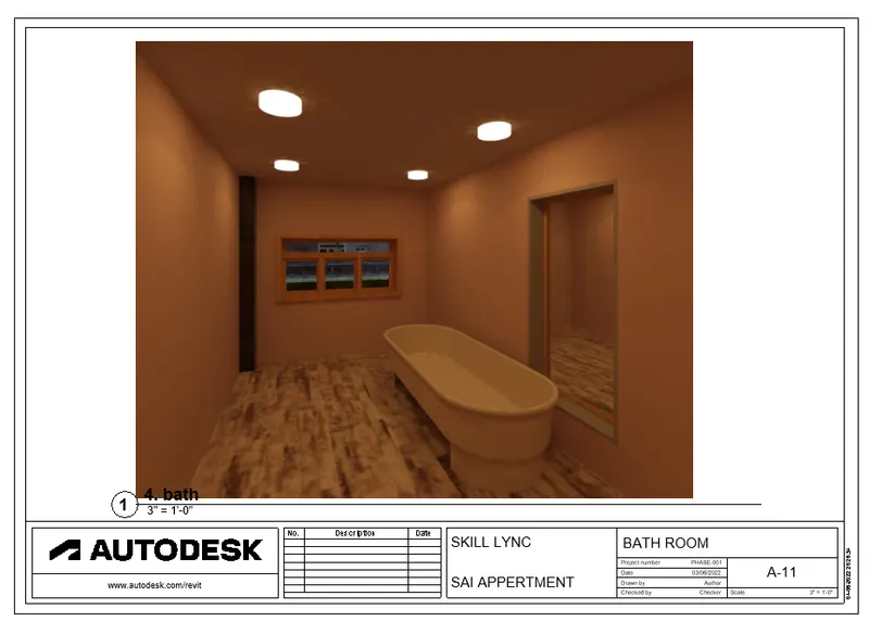
- BATH :
- STAIRCASE
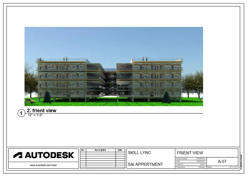
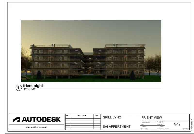
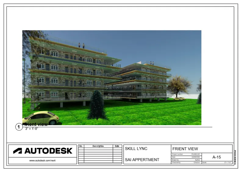
- FRIENT VIEW :
- QUESTION 7 :
- Print the set of drawing sheets created and submit the drawings from the architecture and structure model
- ANSWER :
- PROCEDURE
- STEP 1
- start the revit software
- then homepage of revit is open
- STEP 2
- click on OPEN option from that homepage
- selct the file and open it
- STEP 3
- go to the properties broswer
- then go to the sheet option
- select the proper sheet which we have to print
- then type ctrl+ P
- then open new dialogbox is open as shown below
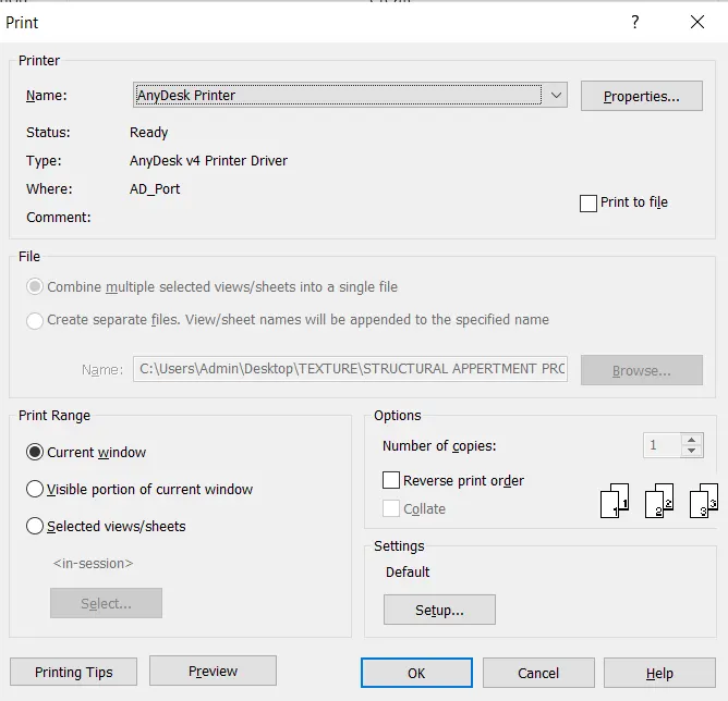
- do proper changes as per our requriment
- then click ok
- and prient the sheet
- RESULTS :
- in this way print the sheet or save a pdf forment