Creating Architectural and Structural model with 3D rendering using REVIT
Week_7 - Creating Architectural and Structural model with 3D rendering using REVIT
1) Select the type of structure you want to build from one of the three below:
a. Multi-Unit Residential Apartment
b. Office Buildings
c. School
AIM: To select the type of structure want to build from one of the three below:
a. Multi-Unit Residential Apartment
b. Office Buildings
c. School.
Answer : School BUILDING
2) Assume reasonable assumptions for geographic and location details for your project modeling. Based on assumptions and type of structure selected identify the modeling requirements from NBC.
Answer:-
While selecting the site of school buildings, the following points
should be kept in mind:
a) Easy accessibility from residential areas;
b) Site should be away from heavy traffic roads, rivers, ponds,
railway tracks, etc;
c) Site should be away from high tension lines;
d) The land should not be of made-up ground unless precautions
have been taken for stabilization;
e) Site should ensure a good natural drainage; and
f) The site should preferably be at a quiet place away from places
generating noise and pollution, such as cinemas, factories and
shopping centres.
- Set-Back Lines — In the absence of local building byelaws the
minimum set-backs of the building from the boundaries shall be as follows:
a) Front set-back 15 metres
b) Side set-back 6 metres - 14.4.1.2 No exit doorway shall be less than 100 cm in width. Doorways shall be not less than 200 cm in height. Doorways for bathrooms,
water-closet, etc, shall be not less than 75 cm wide. - 14.4.2.1 Interior stairs shall be constructed of non-combustible
materials throughout. - 14.4.2.2 Interior staircase shall be constructed as a self-contained
unit with at least one side adjacent to an external wall and shall be completely enclosed. - 14.4.2.3 A staircase shall not be arranged round a lift shaft unless
the latter is entirely enclosed by a material of fire resistance rating as that
for type of construction itself - 14.4.2.4 Hollow combustible construction shall not be permitted.
- 14.4.2.5 The minimum tread shall be 30 cm. The treads shall be
constructed and maintained in a manner to prevent slipping. - 14.4.2.6 The maximum height of riser shall be 15 cm. They shall be
limited to 12 per flight. - 14.4.2.7 Handrails shall be provided with a minimum height of
90 cm from the centre of the tread. - 16. WATER SUPPLY AND SANITARY REQUIREMENTS
16.1 Water Supply Requirements — The arrangements should be
made to supply 45 litres of water per head per day in school buildings
apart from the requirements of water for fire fighting. The laying and
distribution of water supply system should be according to provisions given
in IS : 2065-1972.
3) Using the structural model, include the following components based on the type of structure selected
a. Foundation – Isolated / Wall/Matt Foundation
b. Columns
c. Beams Connected to Columns
d. Roof Framing/ Truss
e. Floor / Decks
f. Floor Openings for Elevators and Stairs
Aim: To create a structural model using structural tools.
Introduction:
The Building Information Modeling (BIM) process is supported by the Structural Analysis Toolkit for Autodesk Revit software, a collection of tools that enables structural engineers to study structures from within the Revit environment. With the help of this toolbox, structural designers and engineers may undertake cloud-based structural analysis using the Revit analytical model, optimising their workflows both online and offline. by connecting the Revit model to the Autodesk Robot Structural Analysis Professional programme or supported third party analysis solutions, as well as by using the Autodesk 360 services. The Revit environment makes it simple to store and study analysis results after they have been completed.
Procedure:
Step 1: Creating base floor Plan
Create base floor plan in AutoCAD For reference

Step 2: Create Grids
Go to structural tab > click on grid option > draw grids.

Open Architectural file created with location map
Go to Inset Tab and Click on LinkCAD
Click open to Link the cad file to REVIT Model
Place the link according to fit between elevation views as shown below
Step 3: Create Structural File
Close Architectural File and Open New Structural Template.
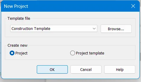
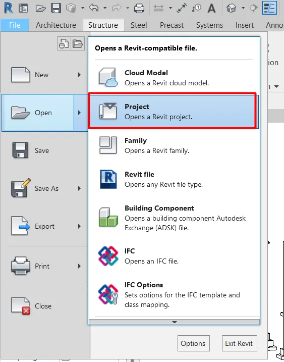
Step 5: Adding Columns to the grids
Go to structural Tab and click on Columns
Change the dimensions of Column as per requirement in 'Edit Type' of 'Column properties'
Three column types are used for this model
- Square Column- 3'X3'(36"X36")
- Rectangular Column- 1'6"X2'(18"X24")
Add the columns respective to the plan and Grids created
The foundation columns are also added to the structure
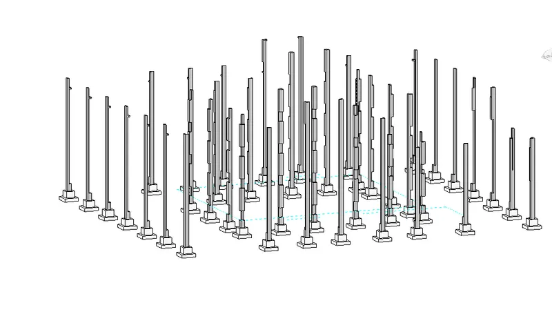
After Adding all columns to the plan on respective grids the columns and Foundation Columns
Top View of Columns
Step 6: Adding Foundations
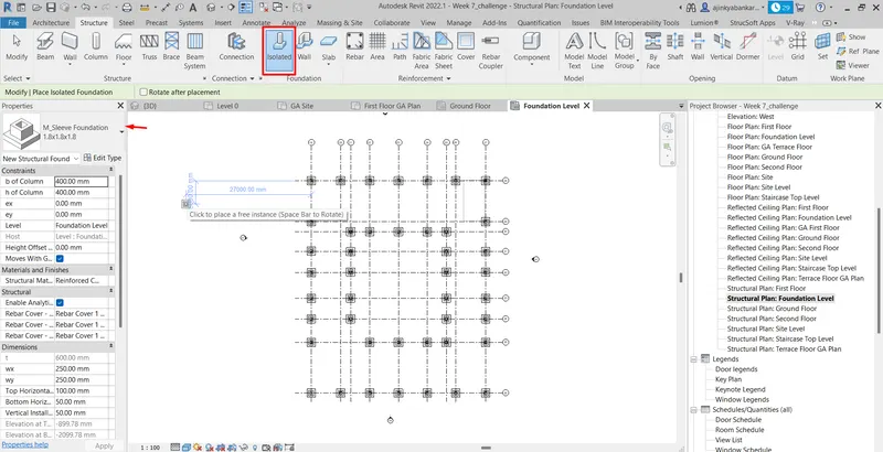
Go to the structural Tab and click on 'Isolated Footing'
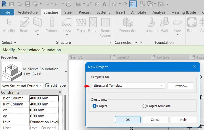
Change the dimensions of footing as per requirement in 'Edit Type' of 'Footing properties'
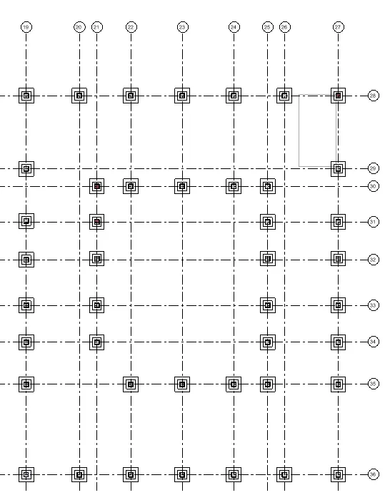
Two footing types are used for this model
- Square Footing- 6'X6'(72"X72"X18")
- Rectangular Footing- 3'X4'(36"X48"X18")
The result after adding Footings to the respective column sizes is shown below

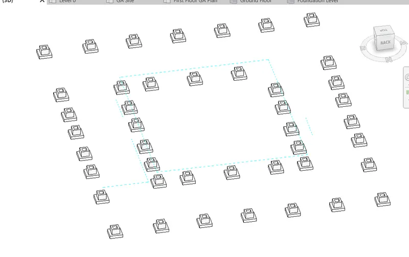
Step 7: Adding Beams
Go to the structural Tab and click on 'Beam'
Change the dimensions of Beam as per requirement in 'Edit Type' of 'Beam properties'
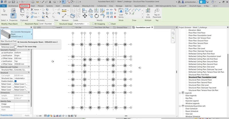
Two Beam types are used for this model
- Rectangular Beam- 3'X2'(36"X24")
- Rectangular Column- 1'6"X2'6"(24"X30")
The result after adding Beams to the respective column sizes is shown below
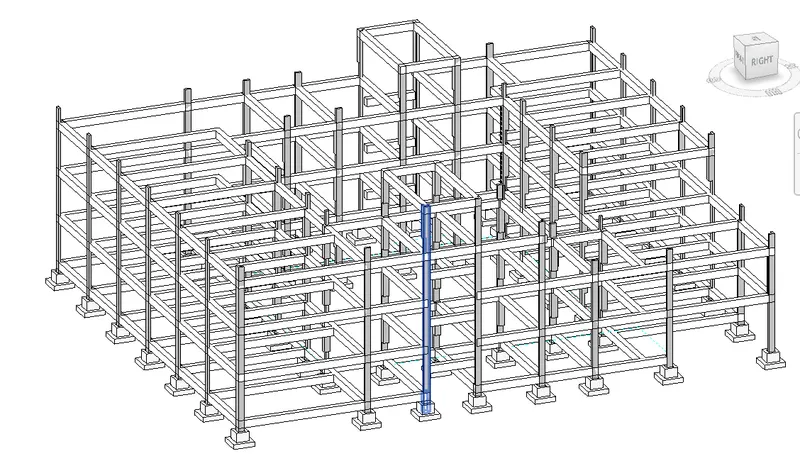
Step 9: Paste to Aligned Levels
As the plan is symmetrical mirror all the elements
Select all the elements of the Ground-floor level such as floor, columns, and beams.
Go to modify tab click on copy and then click on paste dropdown
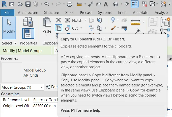
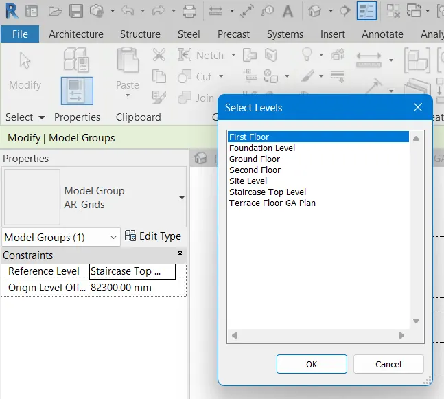
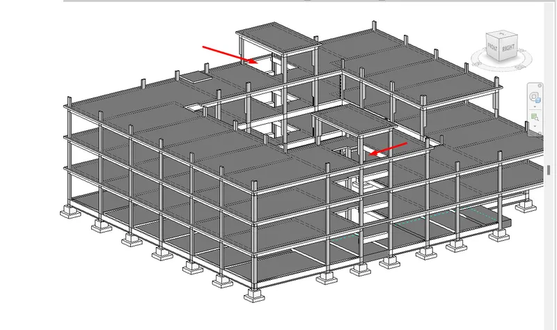
Step 10: Floor Openings for lift and stairs
Lift Opening for ground Floor
Go to Architecture tab > Shaft Opening > click on Shaft > Draw the boundries as per stair shape.

Result:
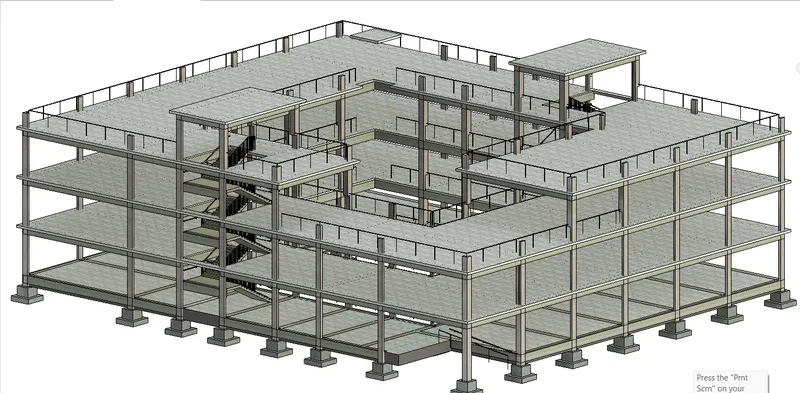
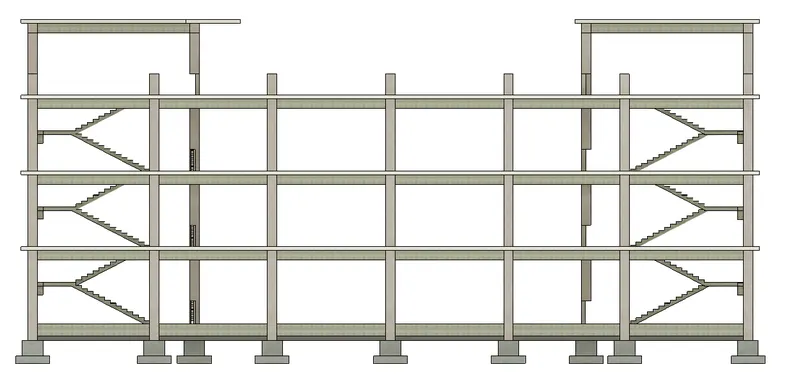
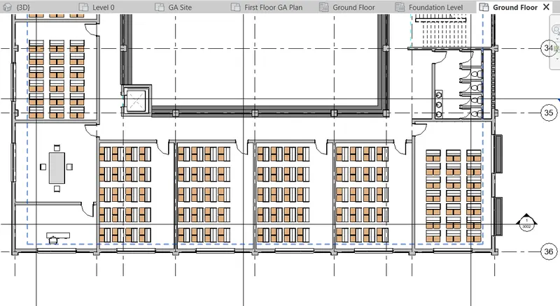
The final drawing of the Ground Floor Plan after adding all components to the building are as follows.
4) Using the architectural model, include the following components based on the type of structure selected
a. Wall Layout with appropriate material and finishing
b. Exterior façade with fancy finish
c. Interior partition walls to size rooms
d. Components to add details to a room ( Desk, Chair, Lighting, Plumbing fixtures)
e. Add components such as stairs Elevators
f. Have at-least one side of the building with curtain walls and glass panels
g. Include interior and exterior lighting fixtures
h. Place proper topographic components from outside ( Trees, Parking, Plants) to add details to the model
Answer :
Aim: To create Architectural Elements
Introduction:
Revit is BIM software widely used by architects, engineers, and contractors to create a unified model that all disciplines and trades can use to complete their work. Autodesk Revit was created to support BIM and not to replace BIM.
Procedure:
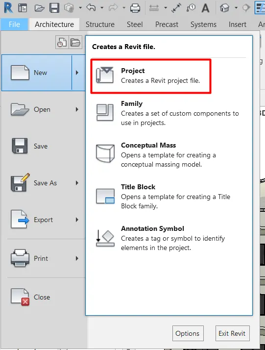
Step 1: Open Architectural Template
Close the structural template and open Architectural Template created earlier.
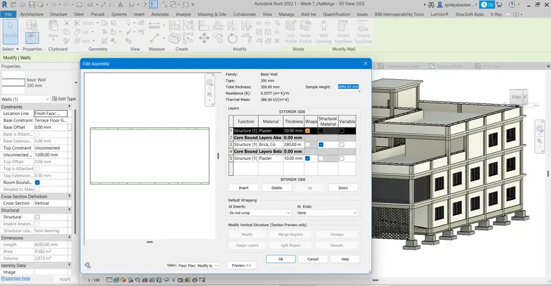
Step 2: Adding Walls
Go to the architectural Tab and click on 'Wall'
Change the dimensions of Wall as per requirement in 'Edit Type' of 'Wall properties'
Three Wall types are used for this model
- Generic- 18''
- Retaining Concrete -9"
- Curtain Wall-Exterior Glazing
The result after adding Wall to the respective places the wall layout is shown below
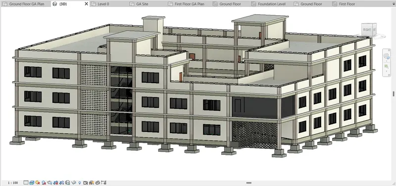
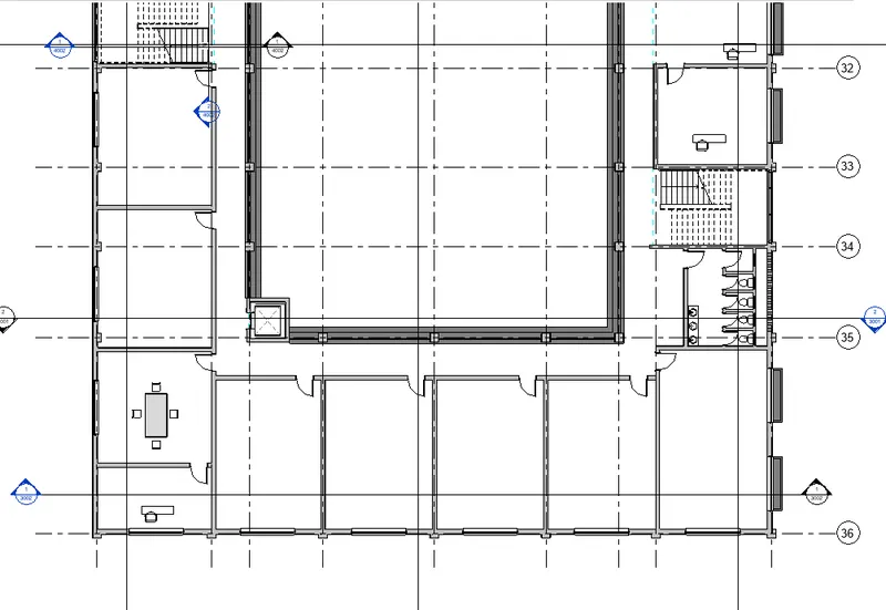
Step 3: Pasting to Aligned Levels
Select all the elements of the Ground-floor level such as floor, columns, and beams.
Go to modify tab click on copy and then click on paste dropdown
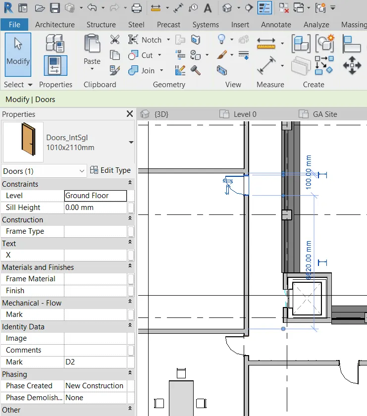
Step 5: Adding Doors and Windows
Doors
Go to Architectural Tab and click on Door
Select a door type and Place it at the required location
The door Types used in this project are
- Double Passage Single Flush
- Double Passage Uneven Flush
- Door Passage Single Vision
Step 6 : Adding Components to Rooms
Reception
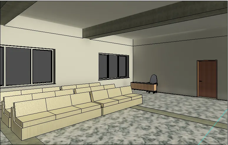
Class Room
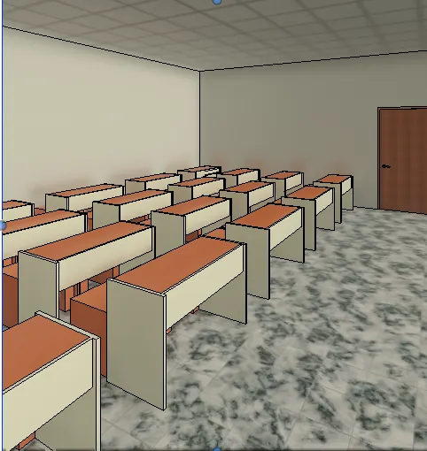
Toilet
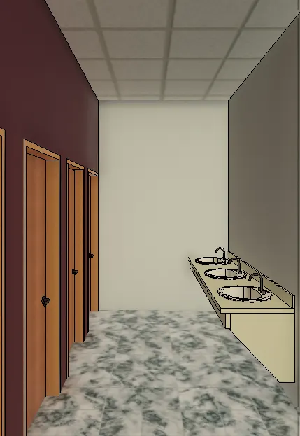
Stairs
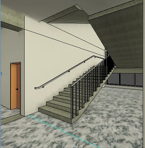
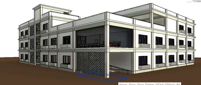
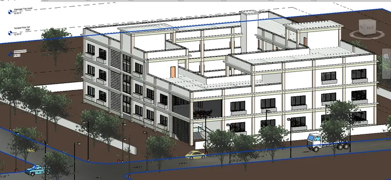
Result:
The final drawing of the Ground Floor Plan after adding all components to the building are as follow
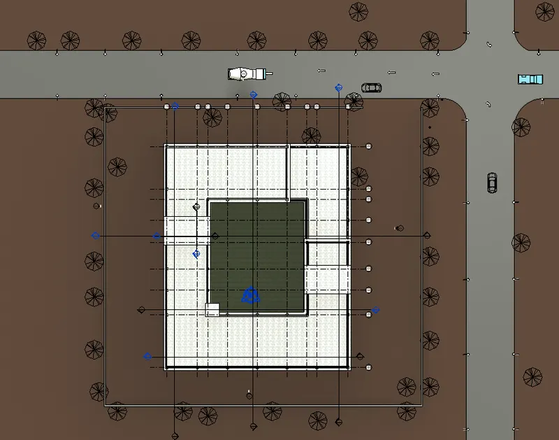
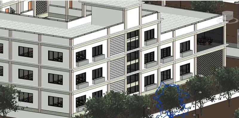
5) Provide a set of drawings in an architectural and structural model to list the following details with categories and appropriate sheet templates included
- Floor Plans with Annotations
- Elevations
- Sections
Aim: To Provide a set of drawings in an architectural and structural model.
Introduction:
Procedure:
Step 1: Opening Project and Sheet Layout
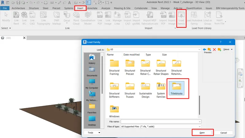
Open the Project " My Home Architectural"
Go to the Insert tab
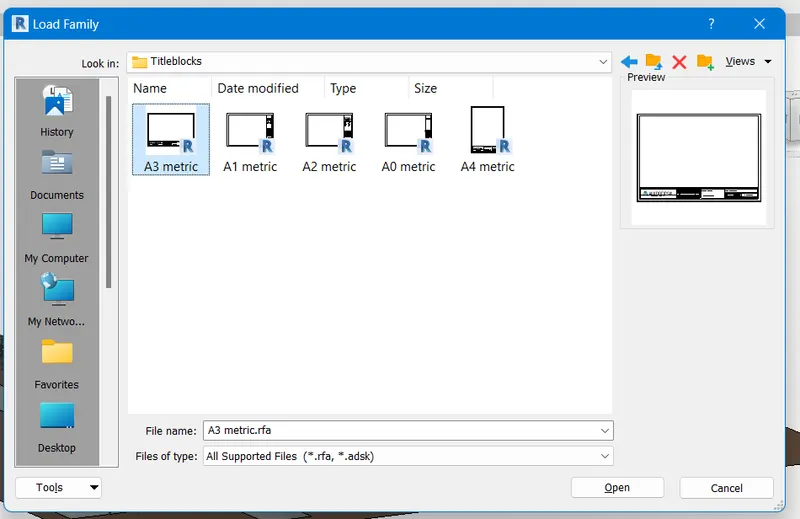
Click on Load Family
- Click on the title block
Click in the respective View to add it to the sheet layout
Adjust the scale settings as per the size of the view
Result:
Respective Sheets of respective views are as follows
Floors Plan
Ground Floor Plan
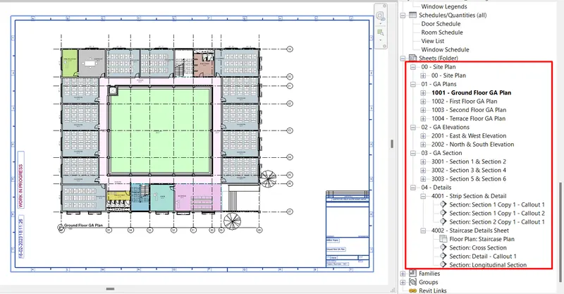
- First Floor Plan
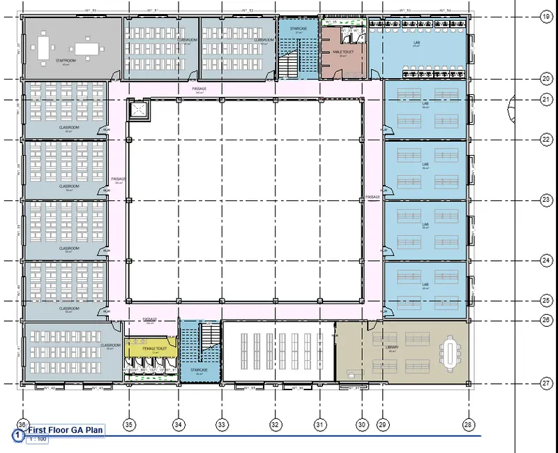
- Second Floor Plan
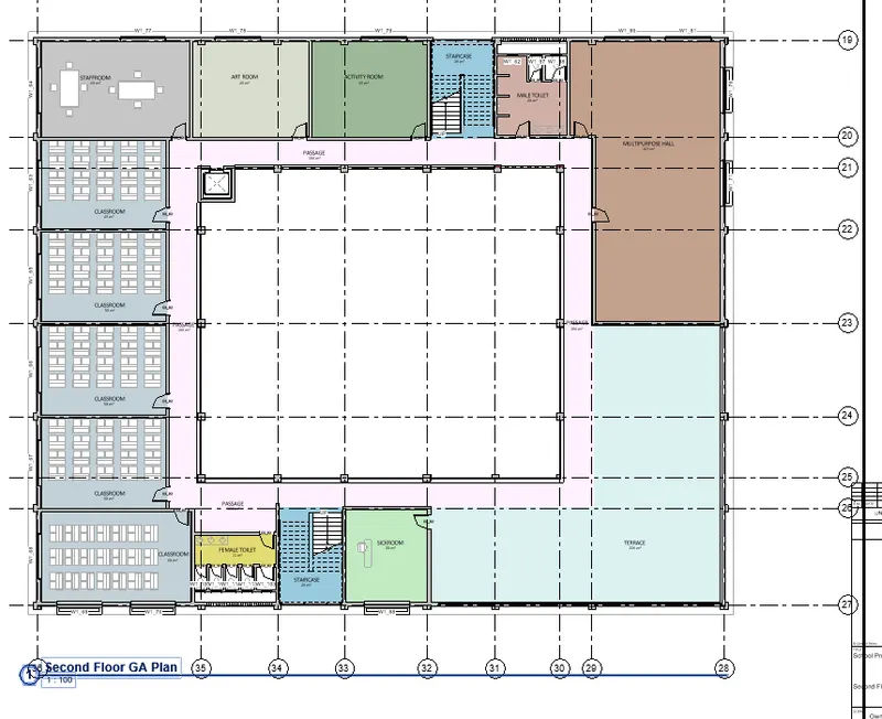
- West Elevation & East Elevation
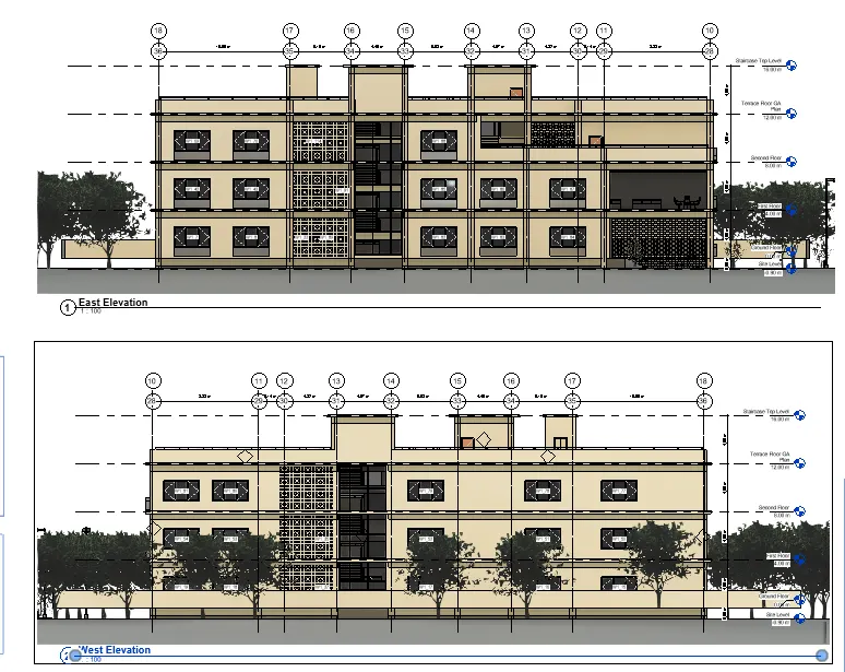
- South Elevation & North Elevation
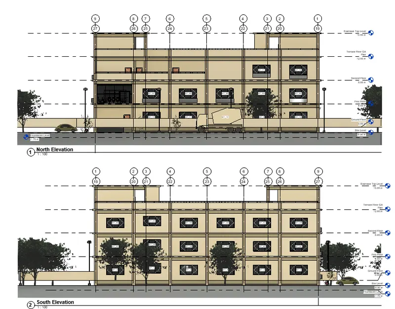
- South Elevation & North Elevation
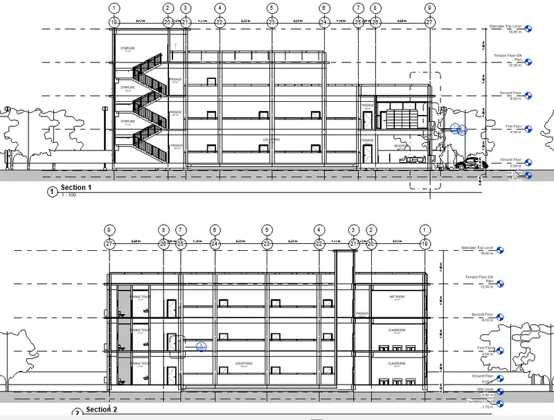
- Annotations & Details
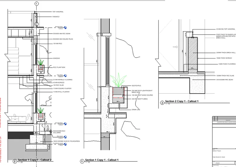
- Staircase Details
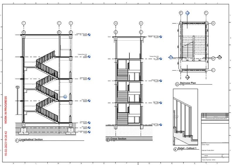
6) Using the Rendering settings, Render images of the 3D model produced and include the rendered images to the drawing sheets
a. Rendering from interior rooms
b. Rendering from out showing topographic features
c. Rendering through structural framing
1. 3D View
Aim - To take renders view from model.
Procedure -
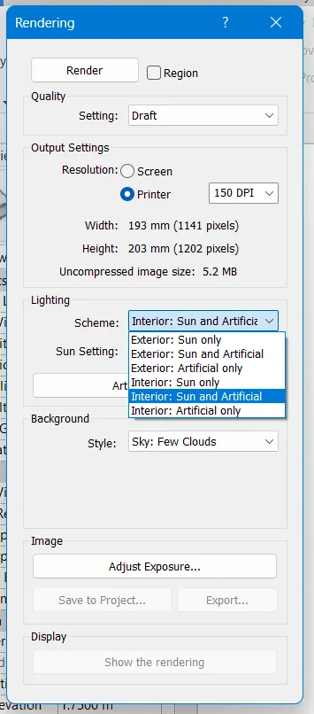
Step 1 - Open Project Browser > Select 3d view > Go to View Tab > Click on render option.

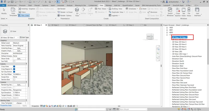
Adjust rendering Settings.
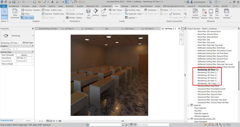
Result :
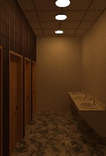
Bathroom -
Reception -
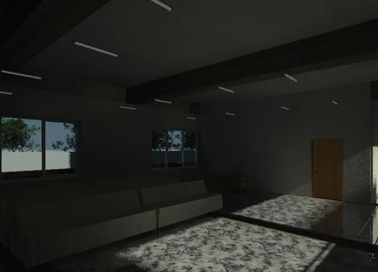
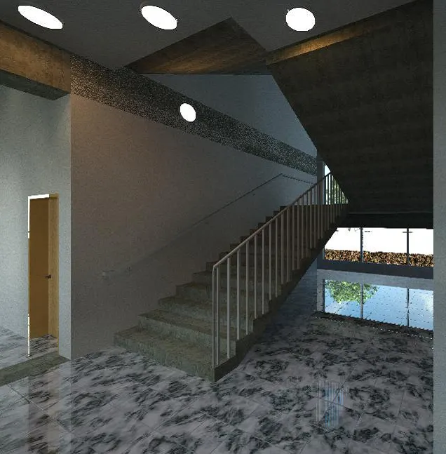
Staircase -
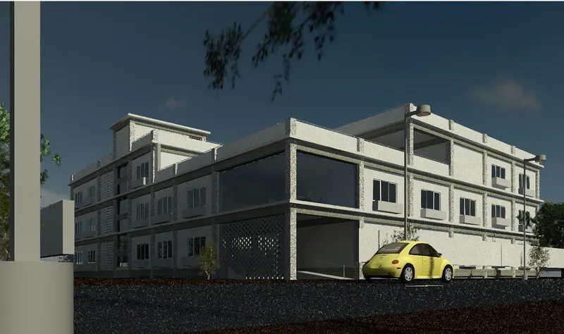
Exterior View :
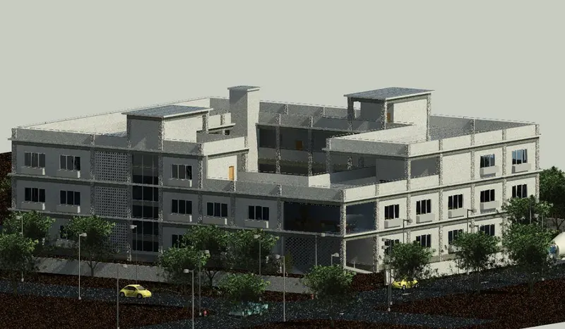
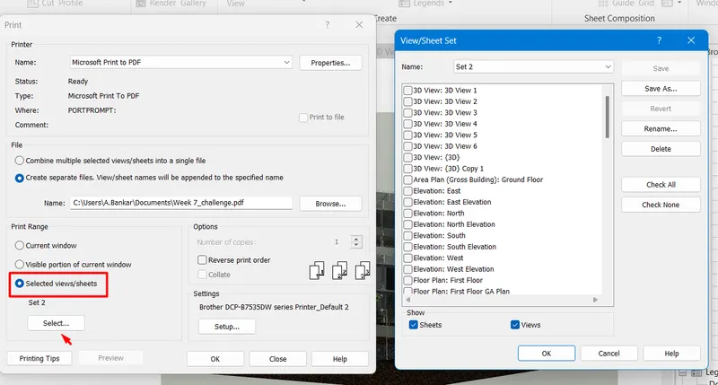
7) Print the set of drawing sheets created and submit the drawings from the architecture and structure model.

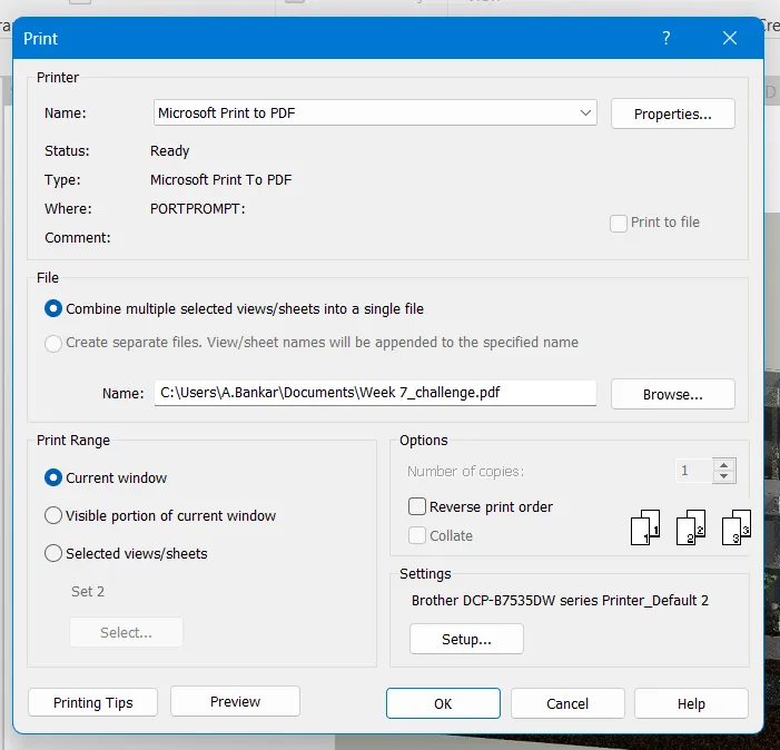
- Tick on Selected Views Or Sheets > Select the set of sheets and save to location.