Creating a Wardrobe detailed drawing, Floor Plan, Kitchen Layout and Column Detail using AutoCad
Ans.1.
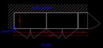
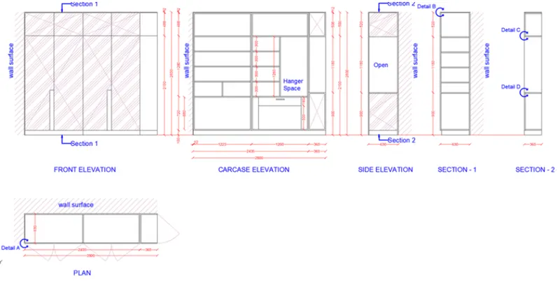
Draw the elevation and details of a wardrobe as shown in the Figure below. After sketching, you need to provide the dimensions and text with the use of layers. Use proper text styles and dimension methods to document it. Also, assume dimensions, wherever needed.
Note: All dimensions are in mm.
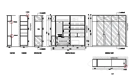
Aim :- Draw the elevation and details of a wardrobe as shown in the Figure in AutoCAD.
Introduction :- Draw the elevation and details of a wardrobe as shown in the Figure. After sketching, you need to provide the dimensions and text with the use of layers. Use proper text styles and dimension methods to document it. Also, assume dimensions, wherever needed.
Note: All dimensions are in mm.
Procedure :-
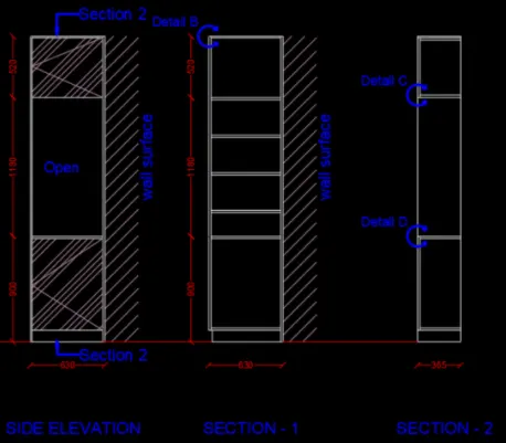
- The front elevation, side and two section view of cabinets are drawn.
- The thickness of shelves is 20mm.
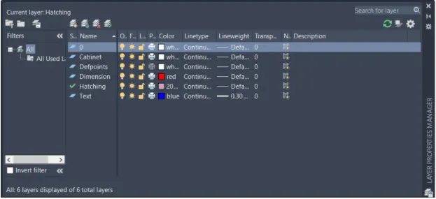
- Layers.
- All the dimenions are in mm.
II. Making of following layout with the given dimensions for the front elevation
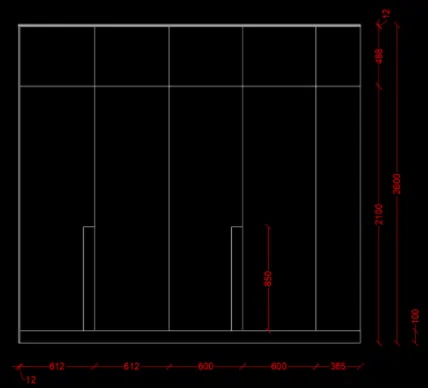
III. Giving hatch on front doors and walls along the required text
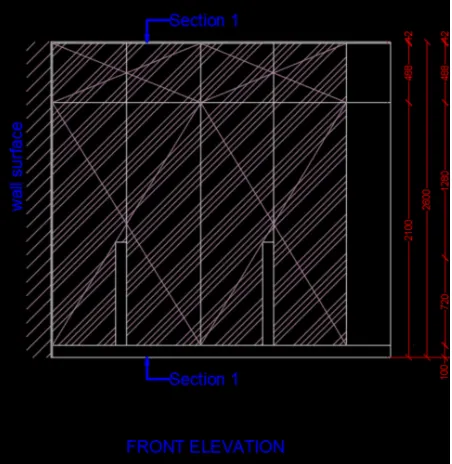
IV. Design the carcase elevation of layout
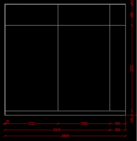
V. Making of inner shelves of wardrobe i.e. Interior of Shelves
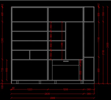
VI. Give hatch and text the details
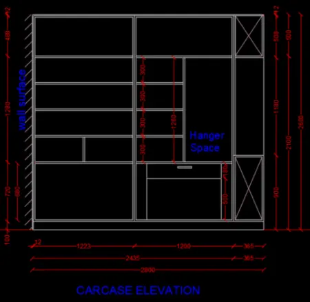
VII. Give the side view of Cabinet
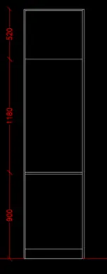
VIII. making of Section 1 and Section 2
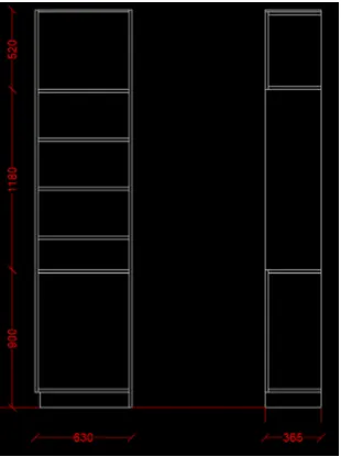
IX. Making of side view and Section view by hatching and texting
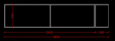
X. Making of Plan view
Result :-
Ans.2.
Draw the floor plan as shown in the Figure. Use the proper drafting tools to sketch the plan. Do not hatch or draw the furniture. You need to draw the floor plan with the following:
Note: You can also import the Floor_Plan.pdf into your current drawing and start working on the project. You need to scale the imported pdf file using reference option. All dimensions are in mm.
- Walls (Exterior and Interior)
Wall Thickness: Exterior Wall- 230mm, Interior Wall: 150 mm (Wherever Required)
- Doors and Windows: Assume the size of the doors and window.
2.1 Stairs: Tread-300mm, Riser-150mm
- Insert Text wherever required
- Insert the dimensions using proper dimension techniques
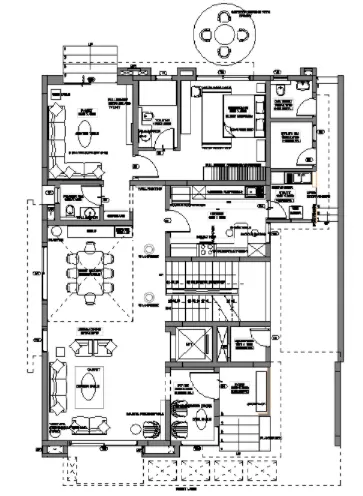
Aim :- Draw the Floor plan as shown in the Figure in AutoCAD.
Introduction :- Draw the floor plan as shown in the Figure. Use the proper drafting tools to sketch the plan. Do not hatch or draw the furniture.
.
Procedure :-
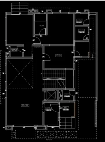
- Insert the floor plan in pdf format and change into the drawing
- Scale the plan as per suitabaility
Result :-
Ans.3.
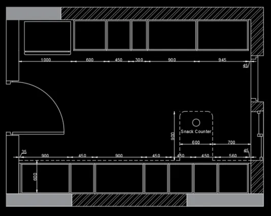
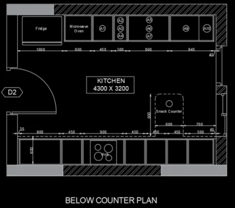
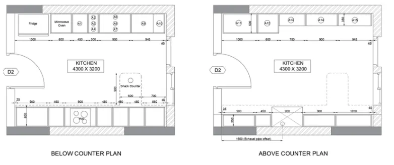
Create the Kitchen Layout as shown in the Figure below. Also, use proper dimension techniques to dimension the kitchen layout. Also, insert text wherever required. All dimensions are in mm.
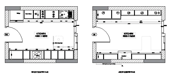
Aim :- Draw the Kitchen Layout as shown in the Figure in AutoCAD.
Introduction :- Create the Kitchen Layout as shown in the Figure below. Also, use proper dimension techniques to dimension the kitchen layout. Also, insert text wherever required. All dimensions are in mm.
Procedure :-
- MAking of layout of kitchen as per the figure shown above
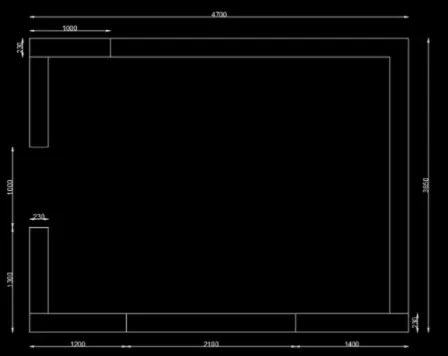
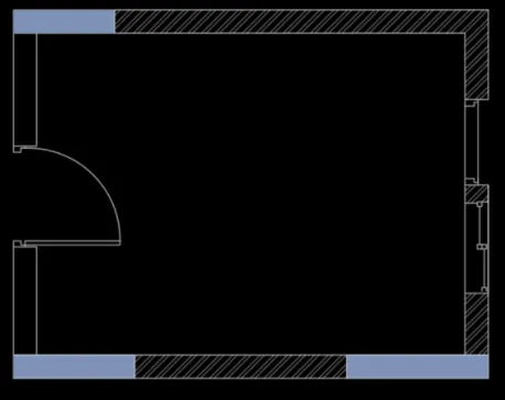
- Giving Hatches to column and walls. give details of windows and doors as shown in above figure
- Making of furnitures as shown in the figure
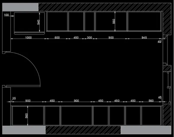
- Make the corner area of snacks into the figure
- Deatailing of Text is then done
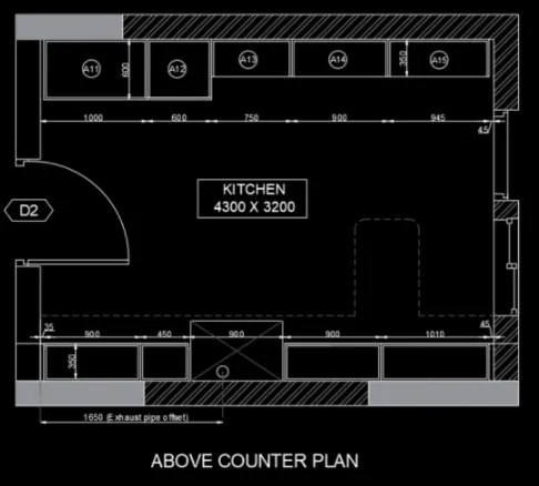
- Copy the counter plan and make necesssary changes to make the above counter plan.(Remove refridgerator, insert chimney hob, reduce the width of cabintes etc
Result :-
Ans.4.
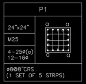
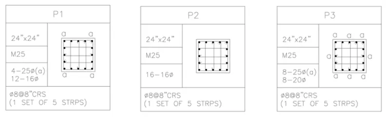
Sketch the column details as shown in Figure. Insert dimensions and text in the figure. Refer to the bar sizes from the schedule.
8mm ---- 0.31 Inches
25mm--- 1 inches
16mm—0.62 inches
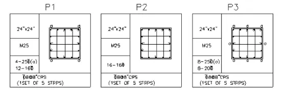
Aim :- Draw the Column details as shown in the Figure in AutoCAD.
Introduction :- Sketch the column details as shown in Figure. Insert dimensions and text in the figure. Refer to the bar sizes from the schedule.
8mm ---- 0.31 Inches, 25mm--- 1 inches,16mm—0.62 inches
Procedure :-
- Make the column section with clear cover of 1.5 inches
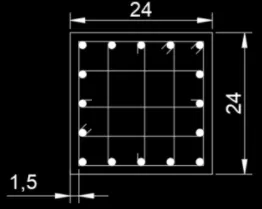
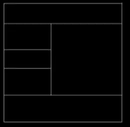
- Sketch the table as shown
- Fill the deatils of column P1
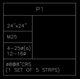
- Move column section into the table
- Making two copy of the column section and name them P2 and P3
Result :-
Ans.5.
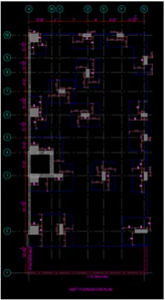
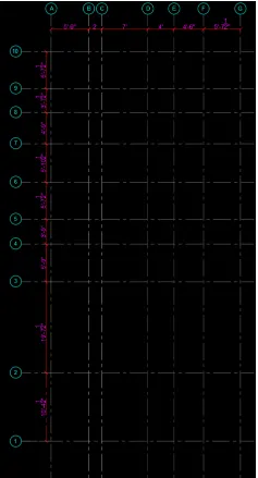
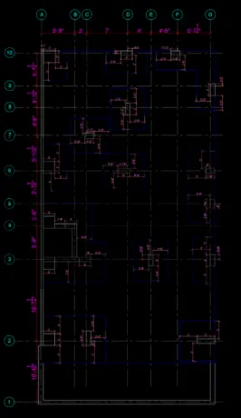
Draw the Raft Layout as shown in the Figure. Assume the column size as per your knowledge. You can take the sizes as: 24”x24”, 9” x 24”, 9” x 18”, and 9’ x 24”. You can import the raft_foundation.pdf to ensure the missing dimensions.
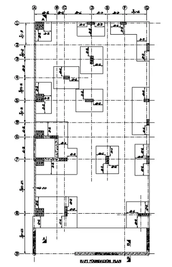
Aim :- Draw the Raft Layout as shown in the Figure in AutoCAD.
Introduction :- The Raft Layout as shown in the Figure. Assume the column size as per your knowledge. You can take the sizes as: 24”x24”, 9” x 24”, 9” x 18”, and 9’ x 24”. You can import the raft_foundation.pdf to ensure the missing dimensions.
Procedure :-
- Width the column size as 2' and 9"
- Layers are made
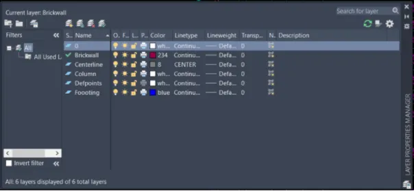
II. Make the grid
III. Sketch the column and footing
IV. Hatch the column, shear wall, and brick wall
Result :-