Creating a Wardrobe detailed drawing, Floor Plan, Kitchen Layout and Column Detail using AutoCad
ASSIGNMENT 6
- Creating a wardrobe detailed drawing, floor plan, kitchen layout and column detail using auto cad ?
Ans -
- Wardrobe details
Procedure :-
o Click on AutoCAD application and open this application
o Type QNEW in command bar and enter
o Select default setting as Metric
o In default setting click on use a wizard and in that advance setting and set unit as decimal precision as 0 and press Next
o Set Angle Measure as EAST and press NEXT
o Set Angle Direction as Counter-Clockwise and press NEXT
o Set Area by providing Length as 100 and Width as 100
o Press finish
o Keep ortho, Object snap >ON
o Keep Snap and Grid > Off
o Un + enter
o Type > Decimal, Precision > O
o Units to scale inserted content > miIimeter
o Enter
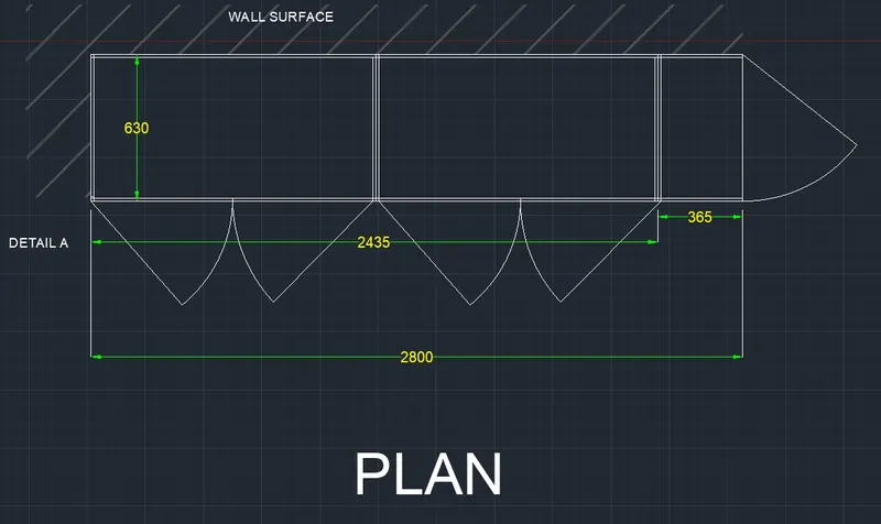
plan -
o Specify first point > randomly
o Specify next point > @2800>0
o Speify next point > @630>90
o Specify next point > @2800>180
o Close
o Take offset command
o Offset all the lines except E side line inside at distance 12
o Of fset the E side a t 365 and at 1200
o Offset the 12m m is shown in drawing
o Offset the left vertical internal line at 605.5mm
o Give offset to last offset line at 5 in both sides
o Similarly second part doors also draw
o Draw a clamp inside the wall of size 20 X 20
o Trim the centre line of the doors
o Doors can be shown by using line command and the circle command
o To show the wall surface
o Use line command at angle of 45
o Copy that line
o Select base point
◊ Click on ARRAY
o- Fit to that line as shown below
o- Click on ANNOTATION tab
o- Click on Dimension
o- Set the characteristics of dimensions
o- Then select linear dimensions
o- Provide at the required place shown below
o- To create the text
o- Click on Annotation tab,
o- Manage textile > New
o- style name as > NEW > OK
o- font Name > Ariel
o- height > 100
o- And press set current
o- Use single line text
o- And fill required text in drawing as shown below
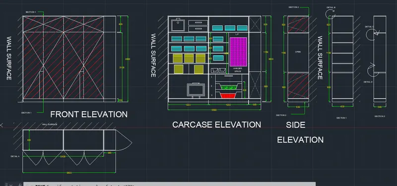
Front Elevation :
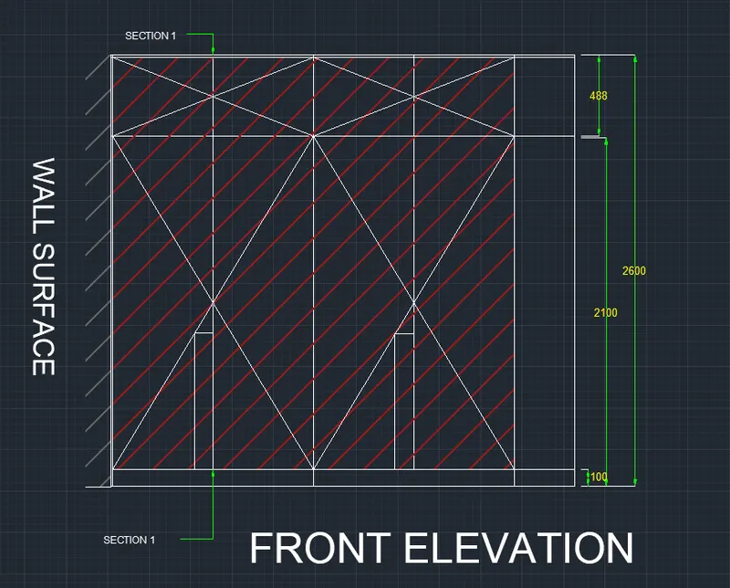
o- Use the construction line to project plan lines
o- Project the construction line from the two comers of the plan
o- Take t he line command
o- draw line perpendicular to the two construction lines
o- Offset the horizontal line at a distance of 100,2700 2588 and 2600
o- Trim the unwanted lines
o- Again take offset command
o- Offset the line distances of 12, 623.5, 1235, 78 35, 2435 as shown below
o- U,se the circle command to show the handles
o- Select circle of random size
o- Trim the required line
o Use the line command to show crosslines design
o To show the wall surface
o use line command at angle of 45
o Copy that line
o Select base point
0 Click on ARRAY
o Fit to that line as shown below
o Use leader dimension to show the section line
0 Click on ANNOTATION tab
o Click on Dimension
o Set the characteristics of dimensions
o Then select linear dimensions
o Provide the linear dimension having height 100mm
o Then take continuous dimension command
o And provide continuous dimension
o Provide a t the required place just like shown below
o To create t he t ext
o Click on Annotation tab > Sing le line
o Manage textile > New
o Sty le name as > NEW > OK
o Font Name > Arial
o Height > 100
o And press set current
o use single line text
o And fill the required text in drawing as shown below
Carcase elevation -
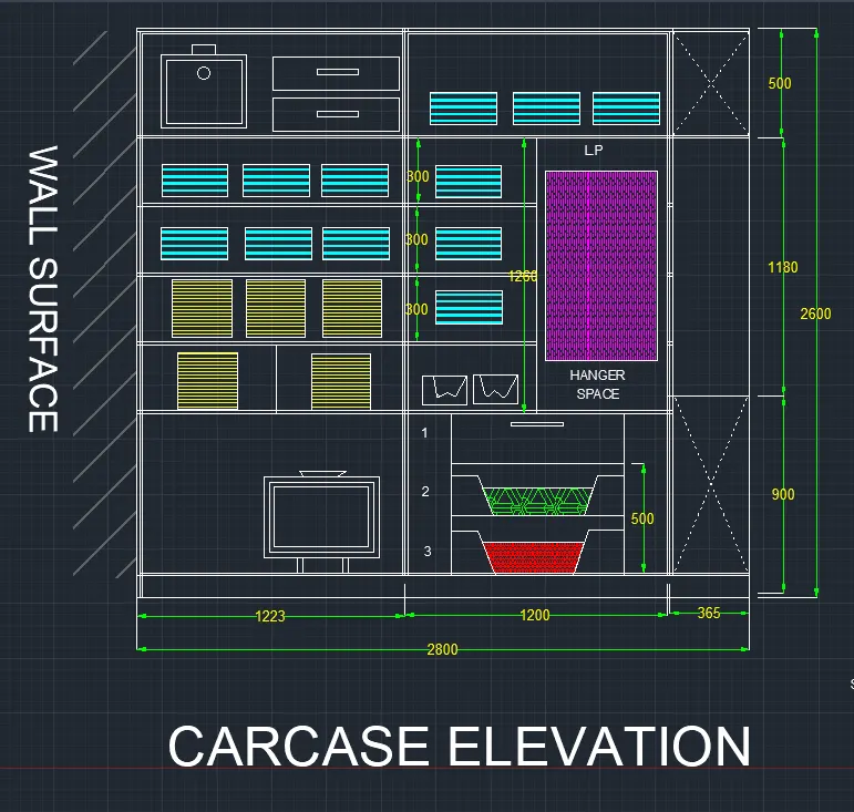
Take linear dimension of 100mm
Then take continuous dimension command
o And provide continuous dimension
o Provide at the required place just like shown below
o Set all the vertical dimension text rotation >90
o Set all the horizontal dimension text rotation > 0
o To create the text
o Click on Annotation tab > Single line
o Manage textile > New
o Sty le name as > NEW > OK
o Font Name > Arial
o Height > 100
o And press set current
o use single line text
o And fill the required text in drawing as shown below
Use line command to show the design
o Use leader dimension to show the section line
0 Click on ANNOTATION tab
o Click on Dimension
o Set the characteristics of dimensions
o Then select linear dimensions
o Provide the linear dimension having height 100mm
o Then take continuous dimension command
o And provide continuous dimension
o Provide at t,he requ,ired place• just like shown below
o Set all the vertical dimension text rotation >90
o Set all the horizontal dimension text rotation > 0
o To create the text
o Click on Annotation tab > Single line
o Manage textile > New
o style name as> NEW> OK
o Font Name > Arial
o height > 100
o And press set current
o Use single line text
o And fill the required text in drawing as shown below
- Section 1
Use the construct ion lines to project the Carcase, elevation lines
O Project the construction Iine from the two comers of the Carcase elevation
<> Take the line command
o Draw the line perpendicular to the two construction lines
<> Offset the vertical line at a distances of 12, 6 18 , 6 3 0
O Trim the unwanted lines
o Again take off set command
o Offset the Horizontal line at a distances of 100 , 780 , 792, 1092 ,1104 , 1404 , 1416 , 1716, 1728 , 2028 , 2040, as shown below
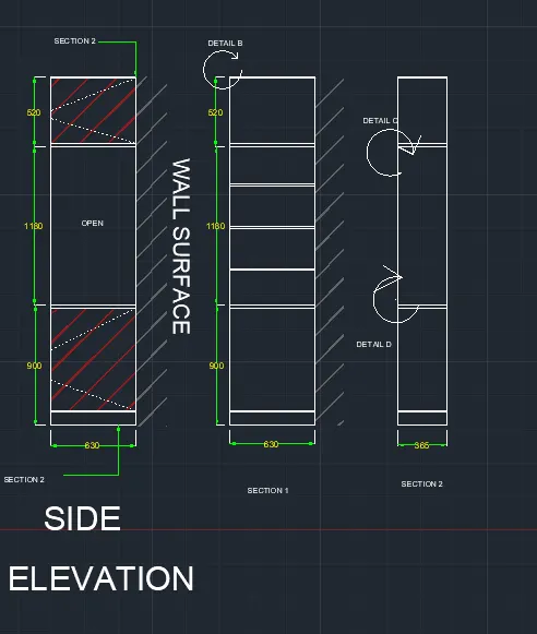
Final drawing
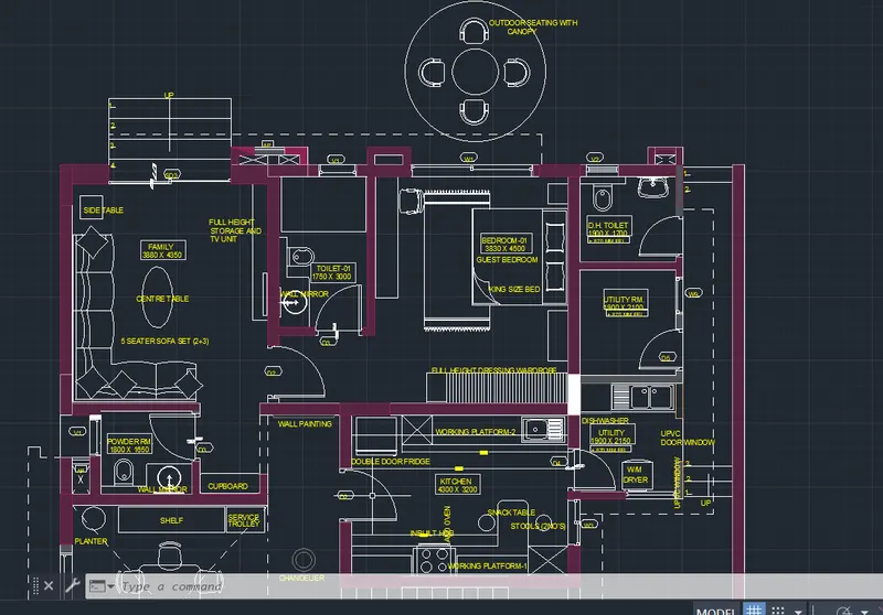
- Floor Plan
- Aim :- To draw the floor plan as shown below
- Procedure :-
o Click on Auto CAD application and open this application
o Type QNEW in command bar and enter
o Select default setting as metric
o In default setting click on use a wizard and in the advance setting and set unit as decimal and precision as 0
and press Next
o Set Angle as Decimal Degree and precision as 0 and click next
o Set Angle Measure as EAST and press NEXT
o Set Angle Direction as Counter- Clockwise and press NE XT
o Set Area by providing Length as 100 and Width as 100
o Press finish
o Keep ortho, Object snap >ON
o Keep Snap and Grid > Off
o Un + enter
o Type > Decimal, Precision > 0
o Units to scale inserted content > miIimeter
o Enter
o Take x line command
o Put x line horizontal ,and x line vertical
o Trim the negative coordinates
o Give the offset of 230mm to show the wall thickness
o In family, Give offset at 3880 of vertical line
o Give wall thickness as 150
o Leave the space for D2
o Leave the space for D3
o Provide off set of vertical line at 3830 for BEDROOM l
o Provide o ff set of horizontal line at 4500 for BEDROOM l
o Give required offsets for the toilet and Utility room
o Leave spaces of door
o Give offsets for kitchen horizontal and vertical
o While providing offsets for room simultaneously provide the offsets for the doors and windows
o Give horizontal and vertical offsets for living room
o Give required offset s to the FOYER
o Give the offsets for the PATIO
o Stairs near the Patio can be assumed as its ,tread is 400
o Assume lift duct size 1520 X 1600
o Provide the staircase of 300mm tread
o Take the centre, provide duct of random size
o Provide t he windows and doors of respective size as per drawing
o Provide the duct s as shown below
o From Properties tab
o Click. on drop down
o Other > Load
o Select AC AD _ISO02W 100 > OK
o Set Global Scale fact or as 40
o To show the doors
o Use the line command
o And give offset to it as 25
o And by using circle command show the doors of respective size
◊ Click on ANNOTATION tab
◊ Click on Dimension
◊ Set the characteristics of dimensions
◊ Then select linear dimensions
◊ Provide at the required place just like shown below
◊ Set arrow size >200
◊ Set Text size > 250
◊ Set all the horizontal and vertical dimension text rotation >
◊ To create the text
◊ Click on Annotation tab > Multiline
◊ Manage textile > New
◊ Style name as > NEW > OK
◊ Font Name > Arial
◊ Height > 200
◊ And press set current
◊ Click on layer properties
◊ Enter New layer
◊ Give layer name > layer colour Enter
o Similarly select the all layers which are required
o The layer name and colour which have chosen shown below
o kept all the layer s ON
o Select the unit and put in to, respective layer
o Select the wall and put it in the wall layer
o Similarly put all the units in respective layers
o After putting in layers
o Take zoom command
o Select window
o Enter
o It will show following results
final drawing
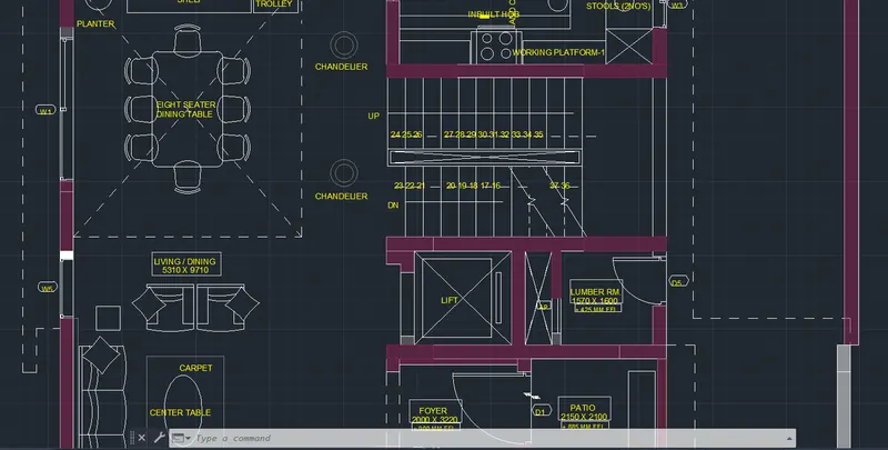
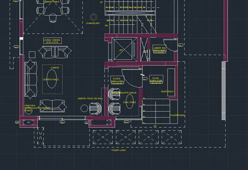
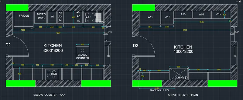
3.KITCHEN LAYOUT
- Aim :- To create the kitchen layout as shown below dig by using AutoCAD Software
Procedure :-
o Click on AutoCAD application and open this application
o Type QNEW in command bar and enter
o Select default setting as Metric
o In default setting click on use a wizard and in that adva nce setting and set unit as decimal and precision as 0 and press Next
o Set Angle as Decimal Degree and precision as 0 and click next
, In default setting click on use a wizard and in that advance setting and set unit as decimal mid precision as 0 and press Next
, Set Angle as Decimal Degree and precision as 0 and click next
,;, Set Angle Measure as EAST and press NEXT
Set Angle Direction as Counter- Clockwise and press NEXT
,;, Set Area by providing length as 100 and width as 100
<:> Press finish
,;, Keep ortho , Object snap >ON
,;, Keep Snap and Grid } Off
,;, Un + enter
,;, Type > Decimal, Precision > 0
,;, U its to scale inserted content > milimeter
enter
- Below Counter ,Plan :
,;, Take x line command
,;, Put x line horizontal and x line vertical
,;, Trim the negative coordinates
,;, Take offset of both lines at 230mm distance
,;, Take offset command
Select distance as 4230 and select object as vertical inner wall line
,;, Again take offset command
,;, Offset the last object at a distance of 230
,;, Trim the un wanted lines
,;, Take offset command
o offset distance > 3200
o Select object > Click on Horizontal line
o Again take the offset to last object at 230
o Trim the un wanted lines
o from Properties tab
o Click on drop down
o Other > Load
0 Select AC AD IS0 02W 100 ) OK
o Set Global Scale Factor as 10
o Provide the dotted line at 600 distance as shown below
o Assume the door size as 1000
o leave the space for door as shown below
o Now to create offsets for fridge, microwave and all
o Offset the Short vertical wall at a distance of 1000, 1600, 2050, 2350, 3250, 419 5 as show n below
o Take a dotted line
o Provide it at a height of 600 from upper horizontal line
o Trim the projection lines
o Assume the thickness as 12
o Take offset command and provide the thickness as given below
o Assume the size of Window as 800 and door near that window size is 800
o From the draw panel
o Click on hatch
o Select ANS l32 hatching
o Select the area where to provide that hatch
o Enter
o Take proper ties of hatching system
o Take scale as 300
o From the draw panel
o Click on hatch
o Select Solid hatching
o Select the area where to provide that hatch
o Enter
o To create the text
o Click. On Annotation tab > Multi- line
o Manage t ext ile > New
o style name as> NEW > OK
o font Name > Arial
◊ font Style > Bold
o Height > 150
o And press set current
o Use Multiline, text
o And f ill the required text as kitchen
o To create the text
o Click on Annotation tab > Multi- line
o Manage t ext ile > New
o Style name as > Ot,her > OK
o Font Nam e > Arial
o font Style >, Regular
Height - 150
o And press set current
o Use Multiline text
o And f ill the required text as shown below
o Use circle command to show the synking hole
o Use the line command, Circle command to show the door as show n below
Above Counter Plan
o Take construction line command
o Take offset of both lines at 230mm distance
o Take offset command
o Select distance as 4230 and select object as vertical inner wall line
o Again take offset command
o Offset the last object at a distance of 230
o Trim the un w an ted line s
o Take offset com m a n d
o offset distance > 3200
o Select object > Click on Horizontal line
o Again take the offset to last object at 230
o Trim the un wanted line s
o Provide the offset at 350mm
o Assume the door size as 1000
o Leave the space for door as shown below
o Take offset command
o Offset the Short vertical wall at a distance of 35, 965, shown below
o Assume the thickness as 12
o Take offset command and provide the thickness as given below
o Use the circle command in chimney to show the exhaust pipe
o Assume the size of Window as 800 and door near that window size 800
o From the draw panel
o Click on hatch
o Select Solid hatching
o Select the area where to provide that hatch
o Enter
o Click on Annotation
o Modify dimension style
o Select arrow size > 50
o Arrow, Dimension line and extension line colour > Yellow
o Text size > 80
o Text c o lour > cyan
o Enter
o Take line a r dimension command
o Provide it to show the 35mm dimension
o Then use continuous dimension Command
o Provide the dimensions
o To opposite side repeat the procedure
o To create t he t ext
o Click on Annotation tab > Multi - line
o Manage textile > New
o Style name as > NEW > OK
o Font Name > Aria l
0 Font Style > Bold
o Height > 150
o And press set current
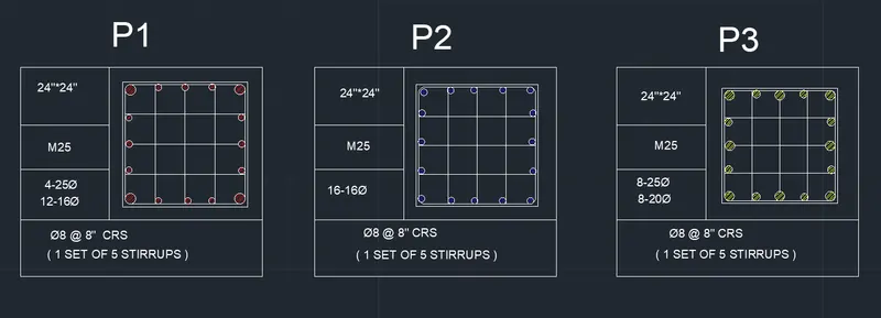
4.column details
- Aim :- To show the co lu m n d eta ills ,a s shown below using AutoCAD So ft ware
Procedure :-
Step : 1 - To Draw the table
Click. on AutoCAD application and open this application
o Type QNIEW in command bar and, enter
o Select default setting as Imperial
o Press Enter
( feet and inches )
o kept snap and grid setting off
o Keep ortho on
o Press UN and enter and set unit
o Type - Engineering
o Precision – 0’0”
o Enter
o Take line command
o Specify first point any where
o Specify next point as= @5'>0
o Specify , next as = @5'>90
o Specify , next point = @5 '>180
o Close· it
Step : 2 - To create and fill the Text in table
o Click on annotation tab > Single line•
o Manage textile > New
o style name as > assignment 6
o Font Nam e· > Aerial
o Height > 4 "
o And press set current
- Write down all the necessary text s shown in schedule
- Keep rotation angle 0 for all the text
- Justify > left
- Take multi line text
- Select first box
- Write > 24" X 24"
- Enter
- Similarly f ill texts in other tab as per above process
Step : 3 - Draw column details
o Pl
o Take rectangle command
o Specify first point > anywhere
o Dimensions > 2' X 2'
o Take offset of rectangle at inner side by 1"
o Explode the last object
o Take divide command
o Divide horizontal and vertical line in four segment Select the object as inner vertical line and inner horizontal line
o Open point :style
o Change the point style
o Use the line command to show the dividat ion
o Again make regular point style
o Take a circle command
o Specify first point anywhere out of rectangle
o Specify diameter as 1 "
o Take hatch command
o Take a solid
o Specify object by clicking on the circle
o Copy that circle wherever it is necessary to show bars
o Take a circle command
o Specify first poin t anywhere out of rectangle
o Specify diameter a s 0.62"
o Take hatch com m and
o Take a solid
o Specify object by clicking on the circle
o Copy that circle wherever it is necessary to show t,he bar s
o Use filet command and select radius as 0.5"
o Select the object by clicking the sides of the inner sides of rectangle just like shown below
P2
o Take rectangle command
o Specify first point > anywhere
o Dimensions > 2' X 2'
<:> Take offset of rectangle at inner side by l"
<:> Explode the last object
o Take divide command
o Divide horizontal and vertical line in four segment
o Select the object as inner vertical line and inner horizontal
line
o Open point style
o Change the point style
o Us e t he line command to show the dividation
o Again make regular point style
<:> Take a circle command
<:> Specify first point anywhere out of rectangle
o Specify diameter as 0.62"
o Take hatch command
o Take a solid
<:> Specify object by clicking on the circle
o Copy that circle wherever it is necessary to show the bars
o U, se filet com m and and select radius ,a s 0.5”
o Select the object by clicking the side s of the inner sides of rectangle just like show below
P3
o Take rectangle command
o Specify first point > anywhere
o Dimension s > 2' X 2'
o Take offset of rectangle at inner side by 1”
o Explode the last object
o Take divide command
o Divide horizontal and , vertical line in four segment
o Select the object as inner vertical line and inner horizontal
line
o Open point style
o Change t,he point style
o Use tile line command to show the dividation
o Again make regular point style•
o Take a circle command
o Specify first point anywhere out of rectangle
o Specify diameter as r
o Take hatch command
o Take a solid
o Specify object by clicking on t he circle
o Copy that circle whe,rever it is necessary to show t, he bars
o Take a circle command
o Specify first point anywhere out of rectangle
o Specify diameter as 0.8”
o Take hatch command
o Take a solid
o Move all tile columns in the respective tab le
o Select the column
o Take scale command
o And scale it as shown below
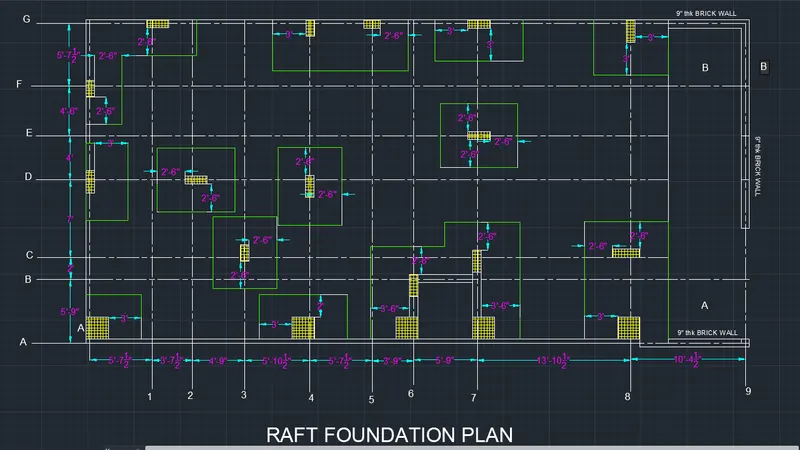
5. draw the raft layout as shown in fig using AutoCAD
Procedure :-
o Click on Auto CAD application and open this application
o Type QNEW in command bar and enter
o Select default setting as Metric
o In default setting click on use a wizard and in that
advance getting and set unit as Architectural and precision as 0'-0 ½, " and press Next
o Set Angle Measure as EAST and press NEXT
o Set Angle Direction as Counter- Clockwise and press NEXT
o Set Area by providing Length as 100 and Width as 100
o Press finish
o Keep ortho, Object snap > ON
o Keep Snap and Grid > Off
o Enter
o From Properties tab
o Click on drop down
o Other > Load
0 Select ACAD_ IS0 08W100 } OK
o Set Global Scale Factor as 2
o Take the line command
o Specify fast point anywhere
o Specify n ex t point as 25'
o Take offset of that line
o At a distance of 10'4 ½’'
o Offset the last object at a distance of 5'9"
o Offset the last object at a distance of 3'9”
o Offset the last object at a distance of 5’½”
o Offset the last object at a distance of 5' ½"
o Offset the last object at a distance of 4'9"
o Offset the last object at a distance of 3'7 W
o Offset the last object at a distance of 5’½’'
o Draw a perpendicular line to all these horizontal line
o Take offset of that line
o At a distance of 10'4½’’
o Offset the last object at a distance of 5'9"
o Offset the last object at a distance of 2'
o Offset the last object at a distance of 7'
o Offset the last object at a distance of 4'
o Offset the last object at a distance of 4'6"
o Offset the last object at a distance of 5’½'’
A- 1 = 2 4 " X 24"
D- 1 = 24" x 9"
F- 1 = 18" X 9"
G- 2 = 9" X 24"
D- 3 = 24" X 9"
C - 4 = 18" X 9"
A-5 = 2 4" X 24"
D- 5 = 24" X 9"
G- 5 = 18" X 9"
A-6 = 24" X 24"
B- 6 = 24" X 9"
A-7 = 24X24"
C7 = 24"x9"
E- 7 = 9" X 24"
A-8 = 24" X 24"
C-8 = 9" x 24"
G- 8 = 24" X 9
o Use A and G centre line to show the wall thickness
o Use t he rectangle command
o Specify dimension as 24" X 9"
o Use t he rectangle command
o Specify dimension as 24" X 24
o U, se the rectangle command
o Specify dimension as 24” X 9"
o Use the rectangle command
o Specify dimension as 9" X 18"
o Use the rectangle command
o Specify dimension as 9" X 24"
o Copy these rectangles. at a proper position, as per drawing
o Use the hatcing command
o For column and concrete wall as shown below
o Click on Annotation
o Manage dimension style
o Modify dimension style
o Select arrow size
o Arrow , Dimension line ,and extension line colour Yellow
o Text size > 1'
o Text colour yellow
o Enter
o Take linear dimension command
o Provide it to show the 10'4’' dimension
o Then use continuous dimension Command
o Provide the dimensions
o To opposite side· repeat the procedure.
- final drawing