Creating a Residence Layout, Seating plan, Toilet and Utility room plan using AutoCad
1A)
AIM:
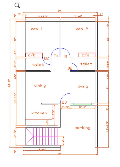
Sketch of the residence layout with help of the autocad essentials
I. In command prompt type (startup:1)
II. Then file>new
III. Then create new drawing window select metric in default settings
IV. In advanced setup in units check on the architectural, angle in degrees, then ok
V. In command prompt type (xl enter h enter v) construction line horizontal and vertical respectively is obtained
VI. Next, In command prompt type(o and specify distance of offset as 9”) and offset the horizontal line to top
VII. Next, In command prompt type(o and specify distance of offset as 6’9”) and offset the horizontal line to top
VIII. Next, In command prompt type(o and specify distance of offset as 9”) and offset the horizontal line to top
IX. Next, In command prompt type(o and specify distance of offset as 18’0.5”) and offset the horizontal line to top
X. Next, In command prompt type(o and specify distance of offset as 4.5”) and offset the horizontal line to top
XI. Next, In command prompt type(o and specify distance of offset as 4’6”) and offset the horizontal line to top
XII. Next, In command prompt type(o and specify distance of offset as 4.5”) and offset the horizontal line to top
XIII. Next, In command prompt type(o and specify distance of offset as 12”) and offset the horizontal line to top
XIV. Next, In command prompt type(o and specify distance of offset as 9”) and offset the horizontal line to top
XV. Next, In command prompt type(o and specify distance of offset as 9”) and offset the vertical line to right
XVI. Next, In command prompt type(o and specify distance of offset as 11’7.5””) and offset the vertical line to top
XVII. Next, In command prompt type(o and specify distance of offset as 4.5”) and offset the vertical line to top
XVIII. Next, In command prompt type(o and specify distance of offset as 11’6”) and offset the vertical line to top
XIX. Next, In command prompt type(o and specify distance of offset as 9”) and offset the vertical line to top
XX. Next, In command prompt type(o and specify distance of offset as 12’6”) and offset the vertical line to top
XXI. Now select all created objects and in command prompt type tr and then trim all the unwanted lines
XXII. And by typing ex in command prompt extend all the required lines
XXIII. Staircase: draw the 3’ line vertical and copy it with co command and array it with 9 objects in the spacing of the 1’
XXIV. Next draw live horizontal connecting the all-vertical lines and join this line to corner with snapping command.
XXV. Select all the created line in the staircase and mirror it with horizontal line as axis with MI command
XXVI. Create doors D1,D2,D3 with help of line command and the arc command (start end direction) with ortho on.
XXVII. And then copy and rotate the doors at the required positions
XXVIII. With help of the aligned dimensions measure the dimensions of the required and with the help of the text add text to show
XXIX. Type dims and modify the required settings of the font size arrow size etc.
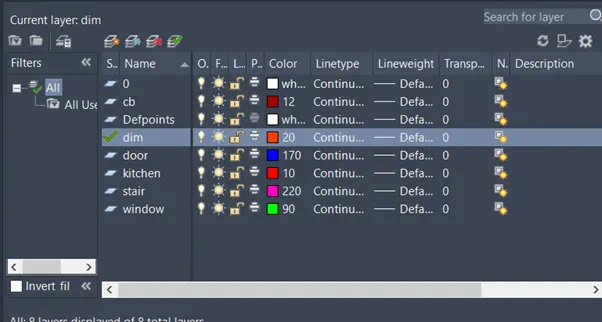
XXX. In layer properties add all the required layers and with the QS quick select tools assign the layers for the objects created.
XXXI. Enter
Result:
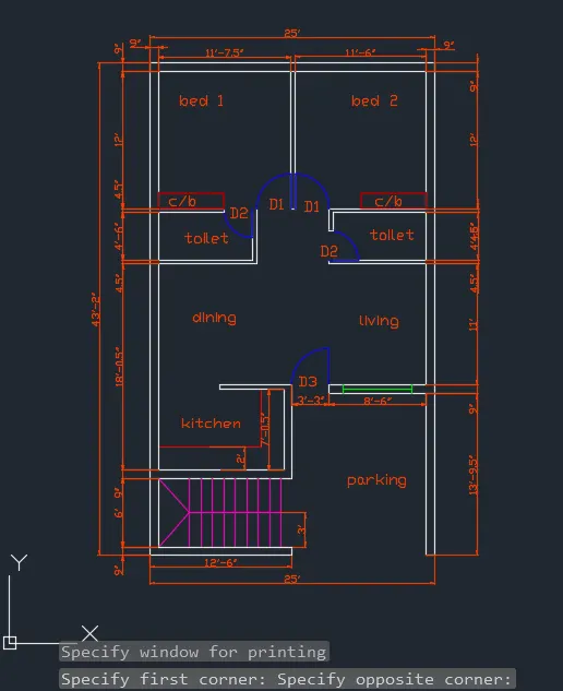
Given layout is drawn in the autocad.
2A)
AIM:
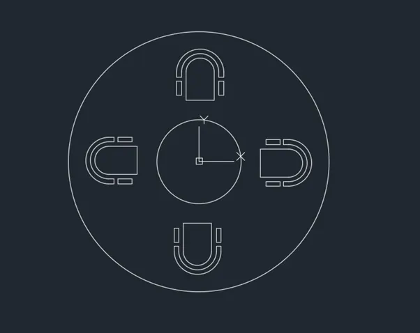
SKETCHING THE AUTOCAD outdoor canopy with the help of the polar array tool.
I. In command prompt type (startup:1)
II. Then file>new
III. Then create new drawing window select metric in default settings
IV. In advanced setup in units check on the decimal,angle in degrees, then ok
V. In command prompt type (CI) where circle command is woken
VI. In command prompt type (specify centre point: 0,0)
VII. In command prompt type (radius:452)
VIII. In command prompt type (CI) where circle command is woken
IX. In command prompt type (specify centre point: 0,0)
X. In command prompt type (radius:1398)
XI. Enter
XII. With line command create the rectangle of 300*150 and the fillet top corners with the 150radius and then offset them by 50 and offset it again by 50
XIII. Copy it to between the both circle with help of the snapping and select them and click on circular array with the 4 objects and select the inner circle.
XIV. Enter
Result:
Sketch of the seating plan for an outdoor canopy was produced
3A)
Aim:
Sketching the layout in the AutoCAD by assuming some assumptions
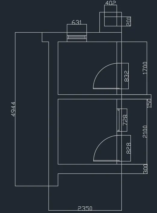
I. In command prompt type (startup:1)
II. Then file>new
III. Then create new drawing window select metric in default settings
IV. In advanced setup in units check on the decimal, angle in degrees, then ok
V. In command prompt type (xl enter h enter v) construction line horizontal and vertical respectively is obtained
VI. Next, In command prompt type(o and specify distance of offset as 300) and offset the horizontal line to top
VII. Next, In command prompt type(o and specify distance of offset as 2100) and offset the horizontal line to top
VIII. Next, In command prompt type(o and specify distance of offset as 150) and offset the horizontal line to top
IX. Next, In command prompt type(o and specify distance of offset as 1700) and offset the horizontal line to top
X. Next, In command prompt type(o and specify distance of offset as 300) and offset the horizontal line to top
XI. Next, In command prompt type(o and specify distance of offset as 210) and offset the horizontal line to top
XII. Next, In command prompt type(o and specify distance of offset as 150) and offset the horizontal line to top
XIII. Next, In command prompt type(o and specify distance of offset as 300) and offset the vertical line to right
XIV. Next, In command prompt type(o and specify distance of offset as 1900) and offset the vertical line to right
XV. Next, In command prompt type(o and specify distance of offset as 150) and offset the vertical line to right
XVI. Now select all created objects and in command prompt type tr and then trim all the unwanted lines
XVII. And by typing ex in command prompt extend all the required lines
XVIII. Create doors D1,D2,D3 with help of line command and the arc command (start end direction) with ortho on.
XIX. And then copy and rotate the doors at the required positions
XX. Enter
Result:
Required layout was drawn in the autocad.