Creating a Floor plan, Footing detail and Isometric view using AutoCad
Aim : To create floor plan, footing detail and isometric view using autocad
Procedure for default settings
- Open autocad application
- Type Qnew and open new drawing
- In create new drawing select wizard
- Select advanced setup
- Set units measurement as engineering, angle as decimal degree, angle measure as east, angle direction as clockwise, area as 9x12 inches and close the tab.
- Now enable the dynamic input, right click dynamic input and choose dynamic input settings. Go to pointer input setting and set default to cartesian format.
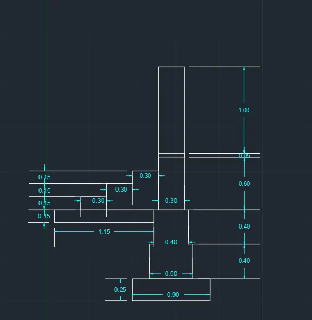
1. Cross-section of load bearing wall over spread footing
Procedure :
- Enter command L for line
- Specify first point 1,1
- Specify next point : @0.9<0
- Specify next point : @0.25<90
- Specify next point : @0.9<180
- Specify next point : @0.25<270
- Press enter
- Enter line command
- Specify first point 1.2,1.25
- Specify next point : @0.4<90
- Specify next point : @0.05<0
- Specify next point : @0.4<90
- Specify next point : @0.4<0
- Specify next point : @0.4<270
- Specify next point : @0.05<0
- Specify next point : @0.4<270
- Press enter
- Enter polyline command
- Specify first point 1.25,2.05
- Specify next point : @0.15<270
- Specify next point : @1.15<180
- Specify next point : @0.15<90
- Specify next point : @0.85<180
- Specify next point : @0.15<90
- Specify next point : @0.3<0
- Specify next point : @0.15<90
- Specify next point : @0.3<0
- Specify next point : @0.15<90
- Specify next point : @0.3<0
- Specify next point : @0.15<90
- Specify next point : @0.3<0
- Specify next point : @0.6<270
- Specify next point : @0.3<180
- Specify next point : @0.6<90
- Specify next point : @0.05<90
- Specify next point : @0.3<0
- Specify next point : @0.05<270
- Specify next point : @1.05<90
- Specify next point : @0.3<180
- Specify next point : @1<270
- Press enter
- Using dimlinear mark the dimensions
Result :
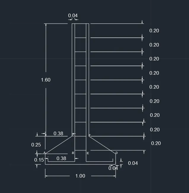
2. Cross section of isolated footing
Procedue :
- Enter line command
- Specify first point 1,1
- Specify next point : @0.15<90 (assume as point A)
- Specify next point : @0.38<0 (assume as point B)
- Specify next point : @0.25<90 (assume as point c)
- Specify next point : @0.85<180
- Specify next point : @1.6<90
- Specify next point : @0.04<0
- Specify next point : @1.96<270
- Specify next point : @0.38<180
- Specify next point : @0.04<0
- Specify next point : @1.96<270
- Specify next point : @0.38<180
- Specify next point : @0.04<90
- Press enter
- Enter command line
- Specify first point 1,1
- Specify next point : @1<0
- Specify next point : @0.15<90 (assume as point D)
- Specify next point : @0.38<180 (aaume as point E)
- Specify next point : @0.25<90 (assume as point F)
- Specify next point : @1.6<90
- Specify next point : @0.04<180
- Specify next point : @1.96<270
- Specify next point : @0.38<0
- Specify next point : @0.04<90
- Press enter
- Enter command line
- Specify first point 1.42,1.2
- Specify next point : @0.16<0
- Press enter
- Enter command offset and enter offset distance as 0.2
- Select the object for offset and continue doing offset upto the top of diagram
- Join AC and erase AB,BC
- Join DF and erase DE,EF
- Press enter
- Using dimlinear mark the dimensions
Result :
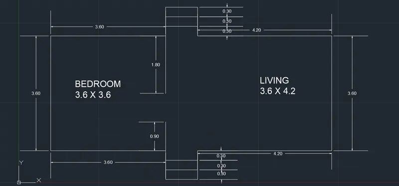
3. Line diagram of two bedroom building
Procedure :
- Enter command Polyline
- Specify first point 1,1
- Specify next point : @3.6<0
- Specify next point : @0.9<270 (assume as point A)
- Specify next point : @1<0
- Specify next point : @0.9<90
- Specify next point : @4.2<0
- Specify next point : @3.6<90
- Specify next point : @4.2<180
- Specify next point : @0.9<90 (assume as point B)
- Specify next point : @1<180
- Specify next point : @0.9<270
- Specify next point : @3.6<180
- Specify next point : @3.6<270
- Press enter
- Enter command line
- Specify first point 4.6,0.7
- Specify next point : @1<0
- Press enter
- Enter command offset and enter offset distance as 0.3
- Select the object for offset and press enter
- Enter command line
- Specify first point 4.6,4.9
- Specify next point : @1<0
- Press enter
- Enter command offset and enter offset distance as 0.3
- Select the object for offset and press enter
- Enter command line
- Specify first point 4.6,1
- Specify next point : @0.9<90
- Press enter
- Enter command line
- Specify first point 4.6,4.6
- Specify next point : @1.8<270
- Press enter
- Using dimlinear mark the dimensions
Result :
4. Cross section of load bearing wall showing foundation details
Procedure :
- Switch on the ortho mode and snap mode
- Enter command line L
- Specify first point 1,1
- Specify next point 0.45 by moving cursor upward
- Specify next point 0.15 by moving cursor rightside
- Specify next point 0.4 by moving cursor upward
- Specify next point 0.05 by moving cursor right side
- Specify next point 0.3 by moving cursor upward
- Specify next point 0.05 by moving cursor rightside
- Specify next point 0.6 by moving cursor upward
- Specify next point 0.05 by moving cursor rightside
- Specify next point 1 by moving cursor upward
- Specify next point 0.3 by moving cursor rightside
- Specify next point 1 by moving cursor downward
- Specify next point 0.05 by moving cursor leftside
- Specify next point 0.6 by moving cursor downward
- Specify next point 0.05 by moving cursor leftside
- Specify next point 0.3 by moving cursor downward
- Specify next point 0.05 by moving cursor leftside
- Specify next point 0.4 by moving cursor downward
- Specify next point 0.15 by moving cursor leftside
- Specify next point 0.45 by moving cursor downward
- Press close
- Enter command line L
- Specify first point 1.15,1.45
- Specify next point 1.75,1.45
- Press enter
- Enter command line L
- Specify first point 1.3,2.75
- Specify next point 1.9,2.75
- Press enter
- Using dimlinear mark the dimensions
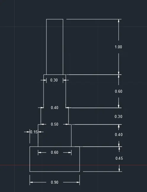
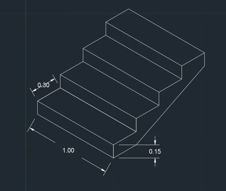
5. Isometric view of steps
Procedure :
- Switch on the ortho mode and snap mode
- Enter command line L
- Specify first point 1,1
- Specify next point 0.15 by moving cursor downward
- Press enter
- Switch on the isoleft tool and ortho mode
- Enter command line L
- Select previous end point and move cursor left and enter value 1
- Now move cursor up and mention next point as 0.15
- Join to point 1,1
- Now switch to isoright and specify next point as 0.3 by moving cursor right side
- Switch to isoleft and specify next point as 1
- Switch to isotop and specify next point as 3
- Press enter
- Switch on isomode and orthomode
- Enter command line L
- Specify first point by clicking on previous end point
- Switch to isotop and specify next point as 0.3
- Switch to isoright and specify next point as 0.15
- Switch to isotop and specify next point as 1
- Switch to isoright and specify next point as 0.15
- Press enter
- Switch on isomode and orthomode
- Enter command line L
- Specify first point by clicking on previous end point
- Switch to isoright and specify next point as 0.15
- Switch to isoright and specify next point as 0.3
- Switch to isotop and specify next point as 1 towards left
- Specify next point as 0.3 towards left
- Press enter
- Copy the two more steps and place toward upwards
- Drop line L of 0.15 at top right side of steps
- Press enter
- Switch on isomode and orthomode
- Enter command line L
- Specify first point 1,1
- Specify next point 0.15 moving the cursor downward
- Specify next point 0.3 moving the cursor right side
- Join it to previous end point
- Press enter
- Using dimaligned mark the dimensions
Result:
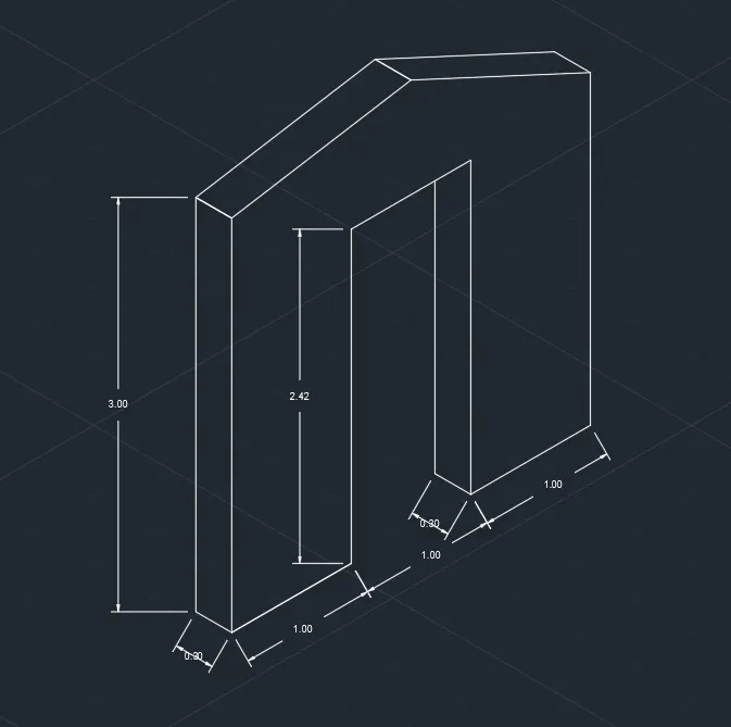
6. Isomteric view of gable wall
Procedure :
- Switch on ortho and isomode
- Enter command line L
- Specify the first point 1,1
- Switch to isoleft and specify next point as 0.3 by moving cursor towards left
- Specify next point as 3 by moving cursor upward
- Specify next point as 0.3 by moving cursor towards topright
- Enter close
- Switch on isomode and ortho mode
- Enter command line L
- Specify the first point 1,1
- Switch to isoright and specify next point as 1 by moving cursor towards right
- Specify next point as 2.42 by moving cursor upward
- Specify next point as 1 by moving cursor towards right
- Specify next point as 2.42 by moving cursor downward
- Now switch to isoleft and specify next point as 0.3 towards left
- Specify next point as 2.42 by moving cursor upwards
- Press enter
- Switch on isomode and ortho mode
- Crop of the extra line
- Switch isotop and Enter line L
- Select first point at right side of base of the door
- Specify next point as 1 by moving towards right
- Switch to isoright and specify next point 3 by moving cursor upward
- Switch to isoleft and specify next point 0.3 by moving cursor left side
- Press enter
- Switchon isoleft and ortho mode
- Enter line L and specify first point from midpoint of base of the wall
- Now draw line 3.25 upwards
- Switch to isotop and specify next point as 0.3
- Press enter
- Join the lines from both sides of the wall to the top
- Using Dimaligned mark the dimensions of the wall