Creating a Floor plan, Footing detail and Isometric view using AutoCad
Q) Draw the following members in detail.
C1. Cross section of load bearing wall over spread footing.
C2. Cross section of isolated footing.
C3. Line diagram of a two bedroom building.
C4. Cross section of a load bearing wall showing foundation details.
C5. Isometric view of steps.
C6. Isometric view of gable wall.
Answer:
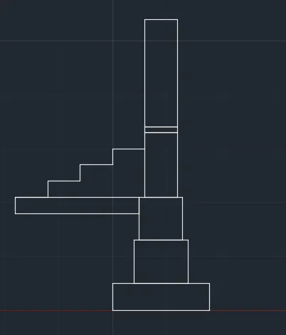
C1. Cross section of load bearing wall over spread footing.
Aim: To draw the cross-section of load bearing wall over spread footing.
Procedure:
Step:1
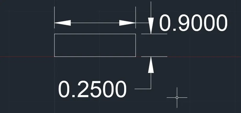
- First we have to enter the rectangle command in the command box.
- Next specify the first corner point (5,0)
- After specifying the corner point as (5,0) then select the dimension options.
- Then enter the length of the rectangle as 0.9 units in the command box.
- Next specify the width of the rectangle as 0.25 units.
- After clicking the enter it forms the rectangle.
Step:2
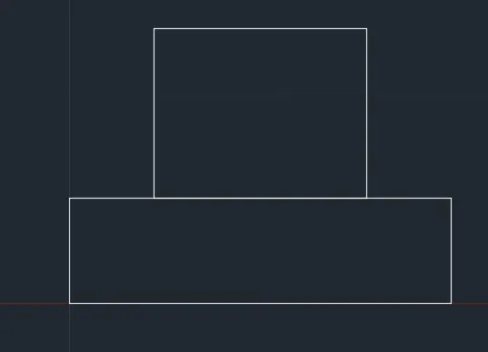
- Next enter another rectangle command in command box.
- Now there is a dynamic input option, then click on that one and it consists of option that ON/OFF, Then select the ON option.
- Next specify the first corner point from the starting point of the rectangle which has drawn first.
- And from the starting point of the first rectangle, Leave 0.2 units from left and right sides of the first triangle we drawin previously.
- Then after clicking the dimensions in command box.
- Then enter the length and width values as 0.5 units and 0.4 units.
Step:3
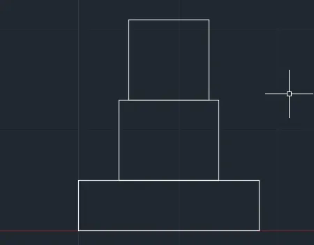
- Similarly, enter another rectangle command in command box.
- Now there is a dynamic input option, then click on that one and it consists of option that ON/OFF, Then select the ON option.
- Next specify the first corner point from the starting point of rectangle which has drawn.
- And from the starting point of first rectangle, Leave 0.05 units from left and right sides of the second triangle we drawn previously.
- Then after clicking the dimensions in command box.
- Then enter the length and width values as 0.4 units and 0.4 units.
Step: 4
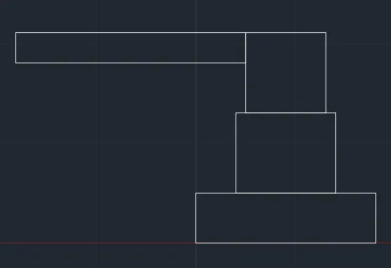
- Next from the starting point of third rectangle, and create the rectangle towards the left using the rectangle command.
- Enter the rectangle in command box, specify starting point towards the left and form a rectangle of length(1.15 units) and width (0.15 units).
- After entering the length and width we get the rectangle attached to the third rectangle which we have drawn previously.
Step:5
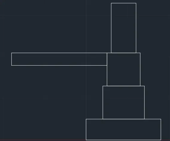
- Then similarly, enter another rectangle command in command box.
- Now there is a dynamic input option, then click on that one and it consists of option that ON/OFF, Then select the ON option.
- Next specify the first corner point from the starting point of rectangle which has drawn first.
- And from the starting point of first triangle, Leave 0.05 units from left and right sides of the first triangle we drawn previously.
- Then after clicking the dimensions in command box.
- Then enter the length and width values as 0.3 units and 0.6 units.
Step:6
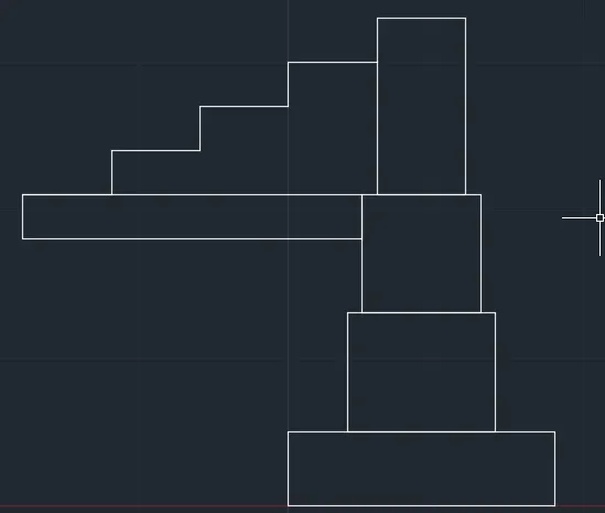
- Now from the previously drawn attached to the third rectangle, On the fourth rectangle we leave the distance of 0.3 units from the left side.
- And draw a line of 0.15 units vertically and 0.3 units horizontally.
- Then continue this more than two times until the 3 steps are created.
Step:7
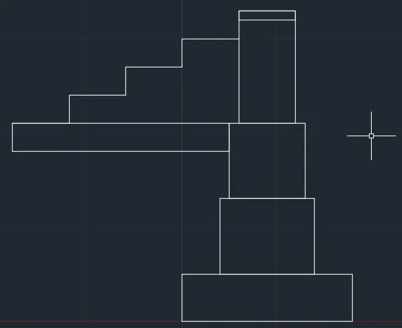
- Next enter another rectangle command in command box.
- Now there is a dynamic input option, then click on that one and it consists of option that ON/OFF, Then select the ON option.
- Next specify the first corner point from the starting point of rectangle which has drawn first.
- Then after clicking the dimensions in command box.
- Then enter the length as 0.3 units and width value as 0.05 units.
Step:8
- Now enter another rectangle command in command box.
- Next specify the first corner point from the starting point of rectangle which has drawn first.
- Then after clicking the dimensions in command box.
- Then enter the length as 0.3 units and width value as 1 unit.
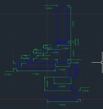
- Then after, put the dimensions for every part in the drawing.
Result:
- The cross-section of a load bearing wall over spread footing was drawn successfully shown in below fig.
Q.2 C2: Cross section of an isolated footing:-
Answer:
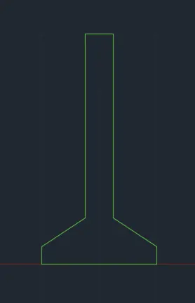
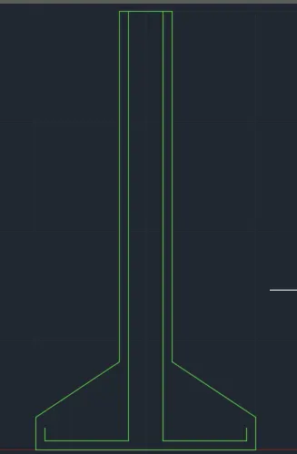
Aim: To draw the cross-section of isolated footing.
Procedure:
Step: 1
- First take the coordinates as (5,0).
- Next we have to draw the line of 1 unit with the Line command.
- Next we have to enter the line command and we have to enter the coordinates as (@0,0.15)
- After giving the first coordinate, then enter the next coordinate as (@0.38,0.25)
- Next give the coordinate as (@0,1.6)
- Next give the coordinate as (@0.24,0)
- Give the next coordinate as (0,-1.6)
- Next give the coordinate as (@0.38,-0.25)
- Next enter coordinate as (0,-0.15)
Step: 2
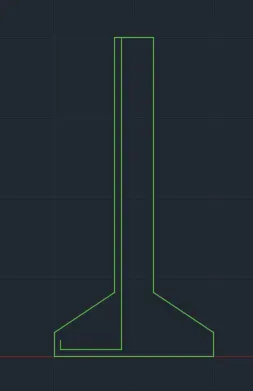
- Next we have to draw the line at a distance of 0.04 from the top using the line command.
- Now there is a dynamic input option, then click on that one and it consists of option that ON/OFF, Then select the ON option.
- After the dynamic input is ON we have to take the of 0.04 and take the coordinates as (@0,-1.96). Then the line will be drawn from 1.96 to downwards.
- Next give the coordinates as (@-0.38,) for the second line.
- Next give the coordinates for the third line as (@0,0.06)
Step: 3
- Next copy the first line by copy command, then click the displacement and enter the value as 0.16 units.
- Then after, copy the second line and move to the desired position.
- Similarly copy the third line and drag it to the desired position.
Step: 4
- Next we have to type the offset command, select the top line, and give the offset value as 0.2 units and offset downwards.
- Continue the offset lines until they reach 9 lines.
- Then trim the unwanted lines.
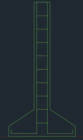
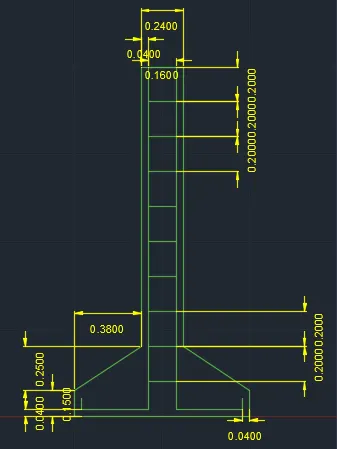
- Finally give the dimensions for every part of a c/s of isolated footing which we have drawn in detail.
Result:
- The cross-section of isolated footing is drawn successfully shown in below fig.
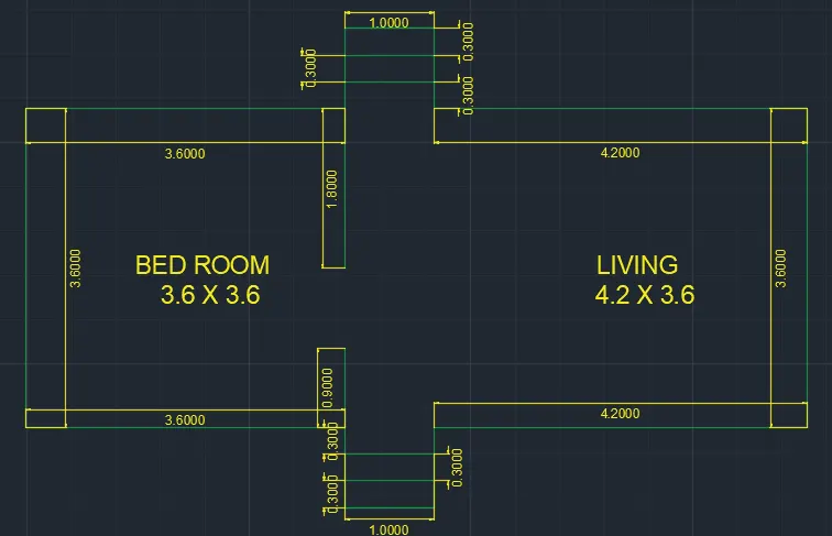
Q.3 C3: Line diagram of two-bedroom building:
Answer:
Aim: To draw the line diagram of two bedroom building.
Procedure:
Step: 1
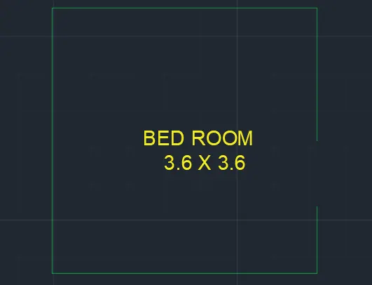
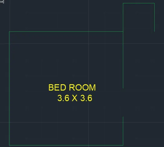
- Here we create the bedroom room of (03.6x3.6) using the polyline command.
- Using the polyline command, click the point and give the coordinates as (@0,-0.9)
- Then after taking the coordinates as (@-3.6,0)
- Next we have to take coordinate as (@0,3.6)
- Next we have to take coordinates as (@3.6,0)
- Then after taking the coordinates as (@0,-1.8)
Step: 2
- Then we have to create the stairs using the line command.
- Here from the corner point of the top right side of the line we take the coordinates as (@0,0.9), The line goes towards the +y axis.
- Next we take the coordinates as (@1,0), and the line goes towards the +y direction.
- Then after we take the coordinates as (@0,-0.9), The line goes towards the -y direction.
Step: 3
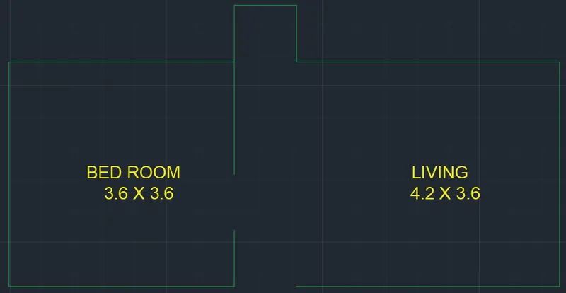
- Here we draw the living room using the polyline command.
- Now we take the coordinates as (@4.2,0) at the last point of the stairs which we have drawn in step:2.
- Then after take the coordinates as (@0,-3.6) The line moves towards the -y direction.
- Afterwards we take the coordinates as (@-4.2,0) The line goes towards the -x direction.
Step: 4
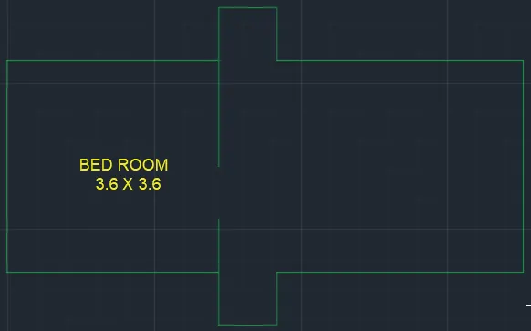
- Now we create the stairs as similarly we created stairs in step:2.
- Let us take a point which has drawn at last in step:3.
- At that point we take coordinates as (@0,-0.9) The line moves towards the -y direction.
- Then after we take coordinates as (@-1,0) The line moves towards the -x direction.
- Now take the coordinates as (@0,0.9) The line moves towards the +y direction.
Step: 5
- Finally we use the offset command for creating the stairs.
- Take the offset command with a dimension of 0.3 units, Then select the object for offsetting.
- Do the offset continuously two times for both sides of the stairs.
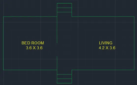
- Finally give the dimensions for all the parts in the drawing.
Result:
- The line diagram of two bedroom building is drawn successfully shown in below fig.
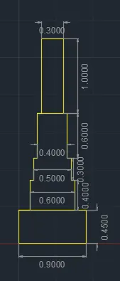
Q.4 C4: Cross section of load-bearing wall showing foundation details.
Answer:
Aim: To draw the cross-section of the load-bearing wall showing foundation details.
Procedure:
Step: 1
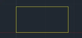
- First we have to enter the rectangle command in the command box.
- Next specify the first corner point (5,0)
- After specifying the corner point as (5,0) then select the dimension options.
- Then enter the length of the rectangle as 0.9 units in the command box.
- Next specify the width of the rectangle as 0.45 units.
- After clicking the enter it forms the rectangle.
Step:2
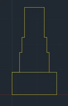
- Next enter the polyline command in command box.
- Now there is a dynamic input option, then click on that one and it consists of option that ON/OFF, Then select the ON option.
- Specify the first point of 0.15 units from the corner of the rectangle.
- Using the polyline command, click the point and give the coordinates as (@0,0.4)
- Then after taking the coordinates as (@0.05,0) The line moves towards the +x direction.
- Next we have to take coordinate as (@0,0.3) The line moves towards the y direction.
- Next we have to take coordinates as (@0,0.6) The line moves towards the y direction.
- Then after taking the coordinates as (@0.4,0) The line moves towards the +x direction.
- Then after taking the coordinates as (@0,-0.6) The line moves towards the -y direction.
- Next we have to take coordinate as (@0.05,0) The line moves towards the +x direction.
- Next we have to take coordinates as (@0,-0.3) The line moves towards the -y direction.
- Next we have to take coordinates as (@0.05,0) The line moves towards the +x direction.
- Next take the coordinates as (@0,-0.4) The line moves towards the -y direction.
Step: 3
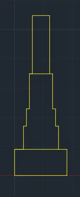
- The top portion is drawn by polyline command.
- Now there is a dynamic input option, then click on that one and it consists of option that ON/OFF, Then select the ON option.
- Specify the first point at a distance of 0.15 unit from the corner which we have drawn last.
- Next we have to take coordinate as (@0,1) The line moves towards the y direction.
- Next we have to take coordinates as (@0.3,0) The line moves towards the y direction.
- Then after taking the coordinates as (@0,-1) The line moves towards the +x direction.
- Then after, put the dimensions for every part in the drawing.
Result:
- The cross-section of load bearing wall showing foundation details were drawn successfully shown in below fig.
Q.5 C5: Isometric view of steps.
Answer:
Aim: To draw the isometric view of steps.
Procedure:
Step: 1
- To draw the isometric view of steps, make sure that turn on the isometric snap in the snap settings.
- And the next turn on the ortho mode.
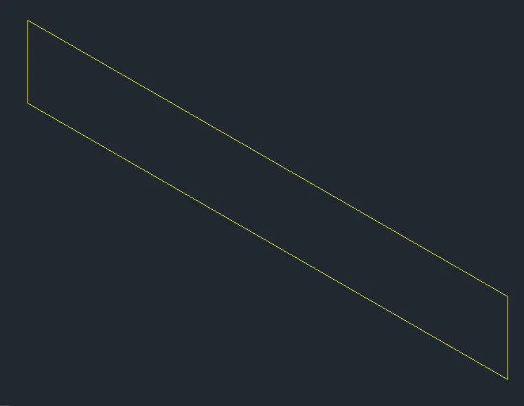
- After selecting the isometric view in the snap settings, select the isophane left option at the bottom of the command box.
- we have to take coordinate as (@-1,0) The line moves towards the -x direction.
- Next we have to take coordinates as (@0,0.15) The line moves towards the y direction.
- Then after taking the coordinates as (@1,0) The line moves towards the +x direction.
- Then after taking the coordinates as (@0,-0.15) The line moves towards the -y direction.
Step: 2
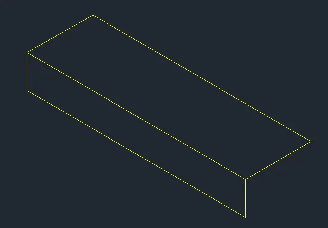
- Change the isometric drafting to the isometric top option.
- Give 0.3 units from the last point.
- Now we move the cursor to the right direction and give 1 unit, and move the cursor to the front and give 0.3 units.
Step: 3
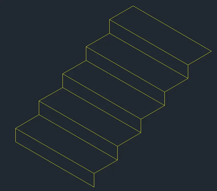
- Now change the isometric drafting to the isometric right option.
- Now turn off the ortho mode and copy the object drawn.
- Next use the copy command and specify the base point and place it to the new point.
- Now this can be continued up to four times in which the steps are formed.
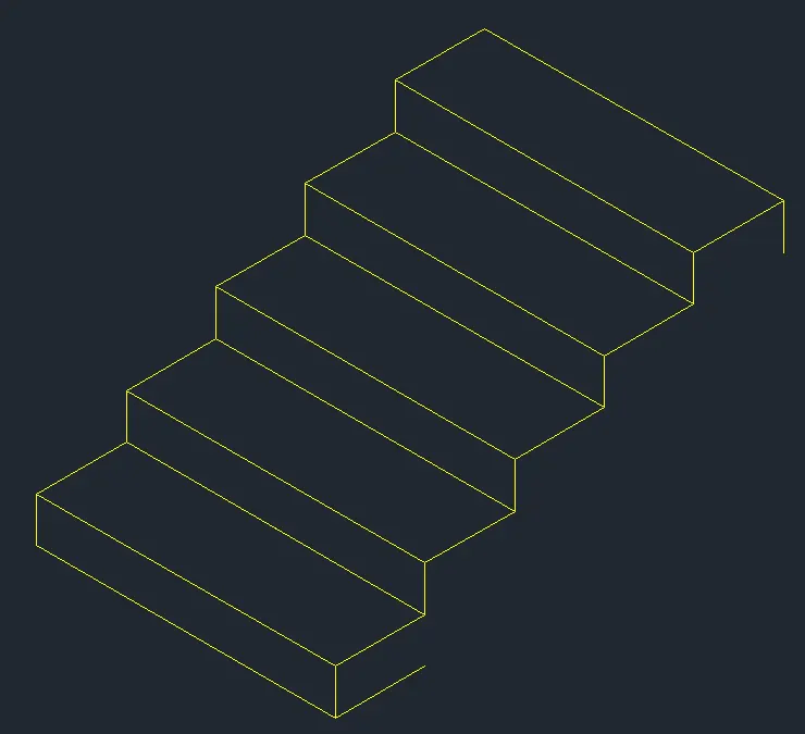
Step: 4
- Now copy the horizontal distance of 0.3 downwards on the starting end of step with isolated right.
- And also copy the vertical distance of 0.15 on the last end of the step.
Step: 5
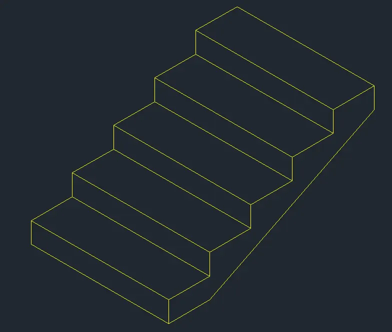
- With the isophane right join the two ends by turning off ortho mode.
- Now use the line command, select the first point as the bottom point.
- And the second point is endpoint of the vertical line.
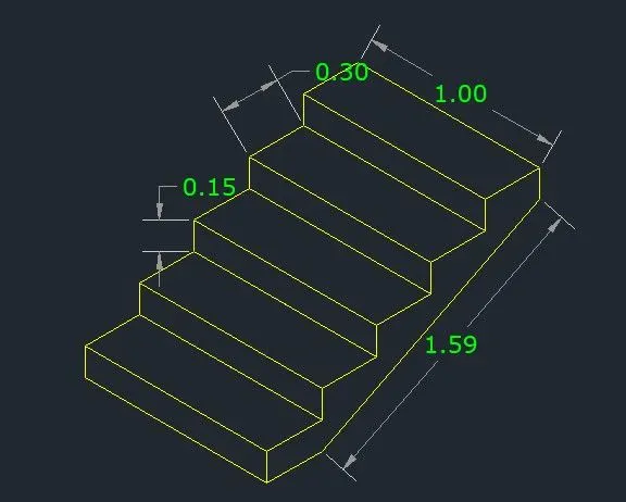
- Finally give the dimensions for every part in the drawing.
Result:
- The isometric view of steps are drawn successfully shown in below fig.
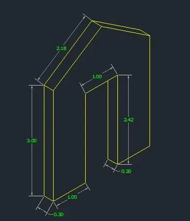
Q.6 C6: Isometric view of gable wall:
Answer:
Aim: To draw the isometric viw of gable wall.
Procedure:
Step:1
- To draw the isometric view of steps, make sure that turn on the isometric snap in the snap settings.
- And next turn on the ortho mode.
- After selecting the isometric view in the snap settings, select the isoplane right option in the bottom of the command box.
- Here we the line command and moving the cursor to left give 1 units.
- Then the point the cursor upwards gives the 3 units
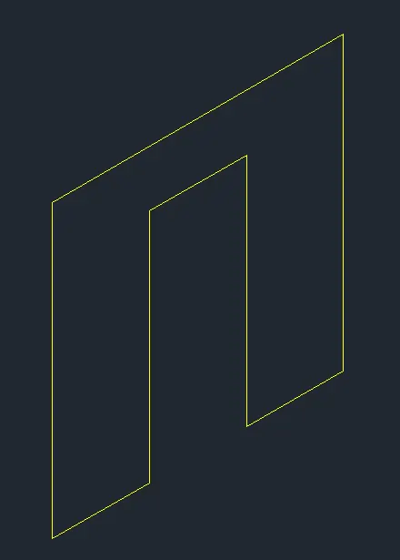
- And draw the 3 units to right and 3 units downwords.
- In the isoplane right, take the line command and draw line upwards of 2.42 units from the starting point.
- Then draw the 1 unit towards the right and 2.42 units downwards.Click the end point of figure.
- So that a closed figure is obtained in the isometric view.
Step:2
- And then change the isoplane left and take the line command and draw the 0.3 units on the left side of the figure.
- And draw 3 units upwards and join the both.

Step:3
- Here give the thickness of opening isoplane left, and draw the 0.3 units towards left and 2.12 units upwards.
- Now increase the thickness line of opening 1.13 units upwards, upto the 3.25 units from the bottom.
- By turning off the otho mode, we draw a line between the corner of left side and the projected line drawn in step:5.
- Then draw it to the other side also till it meets the right corner.
- We draw the vertical line by turning on the ortho mode, and we draw the centre portion and erase the projected and horizontal lines.
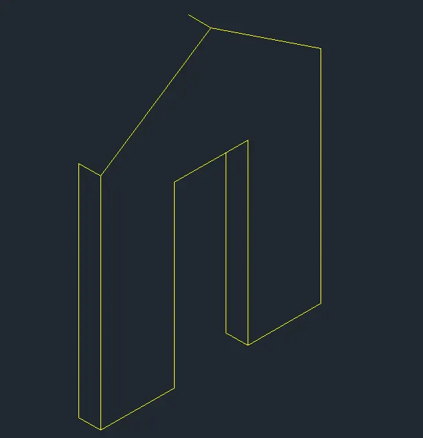
Step:4
- Now copy and join the inclined lines, and we will get the isometric view of the gable wall.
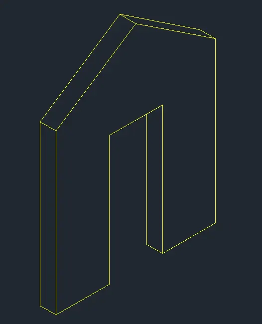
- Finally give the dimensions for every part in the drawing.
Result:
- The isometric view of gable wall is drawn successfully shown in below fig.