Creating a Floor plan, Footing detail and Isometric view using AutoCad
AIM:
To Creating a Floor plan, Footing detail and Isometric view using AutoCAD.
INTRODUCTION:
The main objective of this assignment is to get in touch with various tools in AutoCAD like the rectangle, polylines, modifications tools like copy, move, offset and modes like snap mode and ortho mode. These tools will be understood by creating a footing detail, two bedroom building, cross section of a 2 bedroom building showing foundation details and isometric view of steps and gable wall.
PART I: C.S. OF LOAD BEARING WALL SHOWING FOUNDATION DETAIL
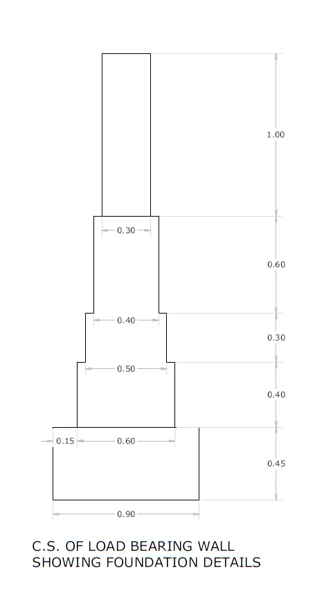
Commands used:
1. Line command [ all coordinate system is used here ]
2. Dimlinear command
3. Text command
The step by step procedure for drawing C. S of load bearing wall is as follows.
PROCEDURE:
STEP 1
giving command L for line
specify the first point : 1,1
specify the next point : 0.45 towards +ve y-axis
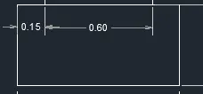
specify the next point : 0.15 towards +ve x-axis
specify the next point: 0.60 towards +ve x-axis
specify the next point : 0.15 towards +ve x-axis
specify the next point : 0.45 towards -ve y-axis
specify the next point : c (close)
STEP 2
Again giving command line L
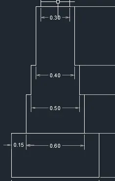
specify the first point : 1.15 , 1.45
specify the next point: 0.40 towards +ve y-axis
specify the next point : 0.05 towards +ve x-axis
specify the next point : 0.30 towards +ve y-axis
specify the next point : 0.05 towards +ve x-axis
specify the next point : 0.60 towards +ve y-axis
specify the next point : 0.05 towards +ve x-axis
specify the next point : @0.30,0
specify the next point : 0.05 towards +ve x-axis
specify the next point :@0.60<270
specify the next point: 0.05 towards +ve x-axis
specify the next point :@0,-0.30
specify the next point: 0.05 towards +ve x-axis
specify the next point :@0,-0.40
specify the next point : *cancel*
STEP 3
For drafting superstructure ,
we take again command line L
specify the first point : 1.3,2.75
specify the next point :@0,1
specify the next point : @0.30,0
specify the next point : @1<270
specify the next point : *cancel*
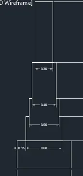
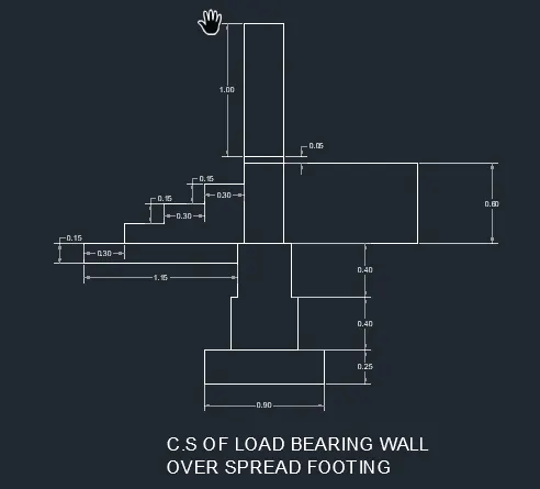
RESULT : The cross section of load bearing wall over spread footing is drawn
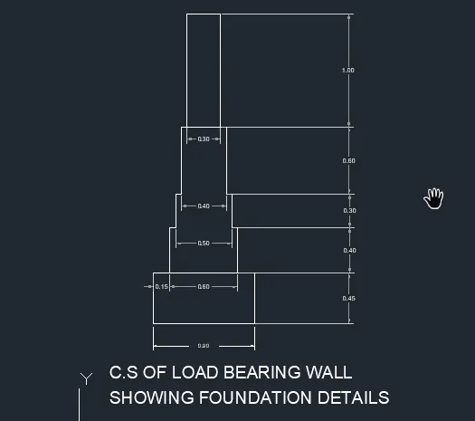
part 2 section of load bearing wall over spread footing.
AIM : to draw cross section of wall over spread footing
Commands used:
- Line.
- Rectangle.
- text command
Procedure
STEP 1: command rec
Specify first corner point : 5,1
Specify other corner point : @0.90,0.25
STEP 2:
ortho mode on
command : line
specify first point : 5.20,1.25
specifing the next point : @0,0.40
specifing the next point : @0.05,0
specifing the next point :@0,0.40
specify the next point : @0.05,0
specifing the next point :@0.30,0
specify the next point : @0.05,0
specifing the next point :@0,-0.40
specifing the next point: @0.05,0
specifing the next point : by moving the cursor to the end point
specifing the next point: *cancel*
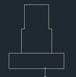
STEP 3 command : REC
Specifing first corner point :5.3,2.05
specifing next corner point : @0.30,0.60
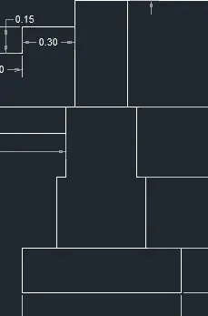
STEP 4: a) drawing of steps using direct distance entry method
command LINE
specifing first point : 5.30,2.5 ( point on top rectangle from where steps start in the above diagram step 3)
specifing point of 0.30 in the command line towards the -ve x-axis ( tread )
specifing next point of 0.15 in the command line towards the -ve y-axis (rise)
specifing next point of 0.30 in the command line towards the -ve x-axis
specifing next point of 0.15 in the command line towards the -ve y-axis
specifing next point of 0.30 in the command line towards the -ve x-axis
specifing next point of 0.15 in the command line towards the -ve y-axis
specifing next point of 0.30 in the command line towards the -ve x-axis
specifing next point of 0.15 in the command line towards the -ve y-axis
specifing next point of 1.15 in the command line towards the +ve x-axis
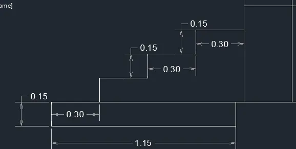
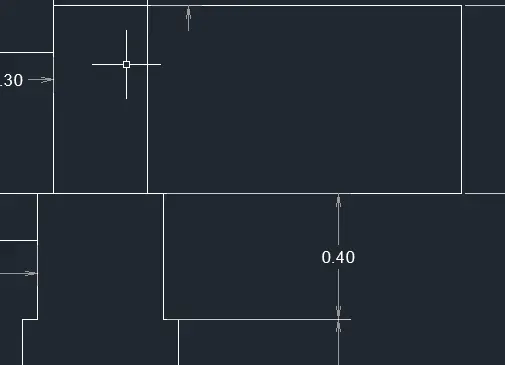
b) drawing of area of flooring assuming 15 mm thick over a bed of 100mm rest filled with gravel and sand
command L
specifing point on right top of rectangle in the given below diagram
next specifing point of length 1.00 in the command line towards +ve x-axis
next specifing point of length 0.60 in the command line towards -ve y-axis
next specifing point of length 1.00 in the command line towards -ve x-axis
specify next point : *cancel*
STEP 5:drafting next top structures using command rectangle
command REC
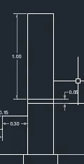
specifing first corner point : 5.3,2.65 ( point on left top rectangle refered in the above diagram)
specifing other corner point :@0.30,0.05
Againg command REC
specifing first corner by clicking cursor on the starting point
specifing other point :@0.30,1
RESULTS:Cross section of load bearing wall over spread footing.
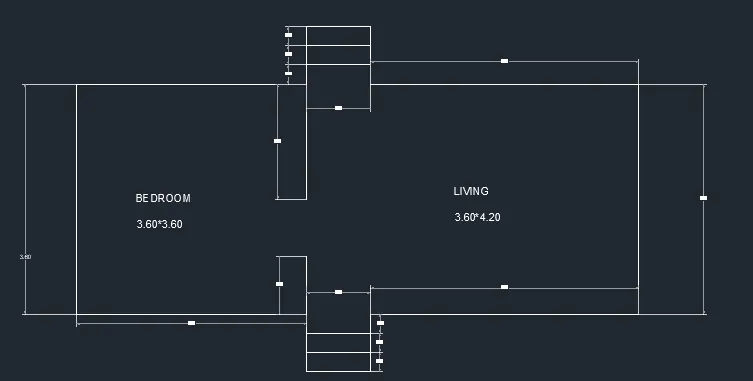
PART III: LINE DIAGRAM OF A TWO BEDROOM BUILDING
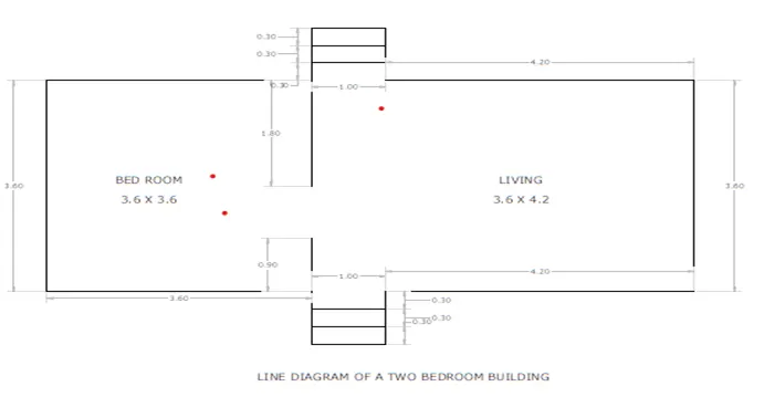
The step by step procedure for drawing line diagram of two bedroom building is as follows.
PROCEDURE:
STEP 1
ortho on (always)
1)using command Line
2)specify first point : 13,1 (drafting of boundary lines of bed room begins)
3)specify the length of 3.60 towards -ve x-axis
4)specify the length of 3.60 towards +ve y-axis
5)specify the length of 3.60 towards +ve x-axis (drafting of boundary lines of bed room ends )
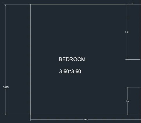
STEPS 2
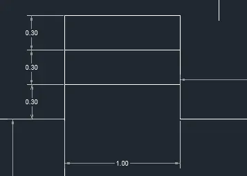
6)specifing the length of 0.30 towards +ve y-axis (drafting of boundary lines of steps on top side of diagram begins)
7)again specifing the length of 0.30 towards +ve y-axis ( repeat this one more time)
8)specifing the length of 1 towards +ve x-axis
9)specifing the length of 0.30 towards -ve y-axis (repeat this two more times)
10) esc and provide command CO
11) copy the length 1 in the procedure 8 and provide base point and paste it at distance 0.30 (twice)
( drafting of boundary lines of steps on top side of diagram ends)
step 3
12) command Line L
13) specify the point using cursor where lines of steps ends [ drafting of living room begins]
14)next specify length 4.20 towards +ve x-axis
15)next specify length 3.60 towards -ve y-axis
16) next specify length 4.20 towards -ve x-axis [drafting of lining of living room ends]
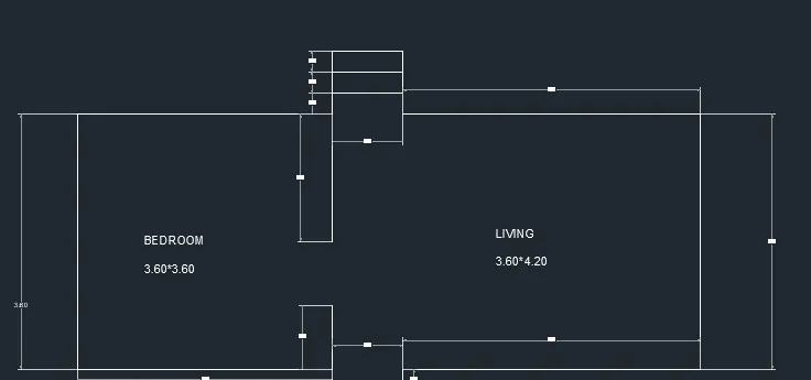
17) specifing the length of 0.30 towards -ve y-axis (drafting of boundary lines of steps on bottom side of diagram begins) repeat this two more times
18)specifing the length of 1 towards -ve x-axis
19)now specifing the length of 0.30 towards +ve y-axis ( repeat this two more time)
20) esc and provide command CO
21) copy the length of 1 in the procedure 18 and provide base point and paste it at distance 0.30 (twice) [drafting of steps end here]
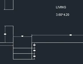
step 5
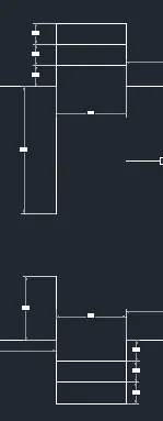
20) now specify a length of 0.90 towards +ve y-axis at the point of begining of bed room lining
21) then at last specify a length of 1.80 towards -ve y-axis at the point of end of bed room lining
RESULT
Part IV: C. S of isolated footing
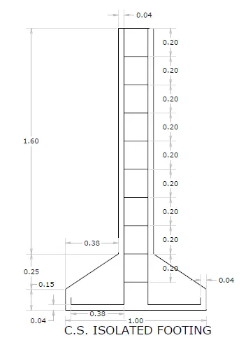
The step by step procedure for drawing C.S of isolated footing is as follows.
PROCEDURE:
|
Type Rec or Rectangle in the command line and press Enter. Specify the first corner of the rectangle. Enter D for Dimensions. Enter the length: 1 Enter the width: .40 Specify the other corner. |
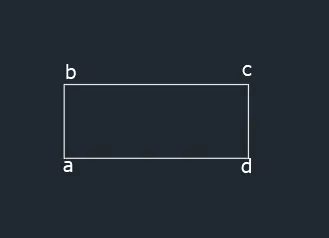 |
|
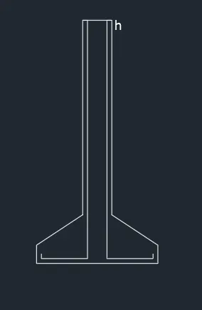
Type CHA or CHAMFER in the command line and press enter Enter D for Distance Specify first chamfer distance:.25 Specify second chamfer distance:.38 Select the first line ab and second line as bc Repeat the same step on opposite side on line cd and bc |
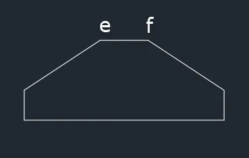 |
|
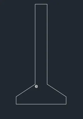
Delete line ef Type L in the command line and press Enter. Specify the start point e. Specify next point:@0, 1.60 Specify next point:@.24, 0 Specify next point:@0, -1.60 |
 |
|
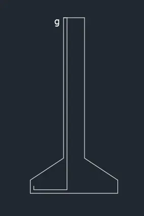
Type L in the command line and press Enter. Specify the start point g. Specify next point:@.04, 0 Specify next point:@0, -1.96 Specify next point:@-.38,0 Specify next point:@0,.04 |
 |
|
Type L in the command line and press Enter. Specify the start point h. Specify next point:@-.04, 0 Specify next point:@0, -1.96 Specify next point:@.38,0 Specify next point:@0,.04 |
 |
|
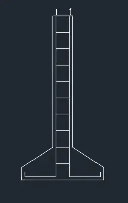
Type L in the command line and press Enter. Specify the start point i. Specify next point:@.12, 0 Type O or offset on the command line and press Enter. Specify the value of offset distance:.20 Select the object to offset ij (We need to select the line ij with a small square cursor.) Move the cursor inside to place the line and continue till required. |
 |
|
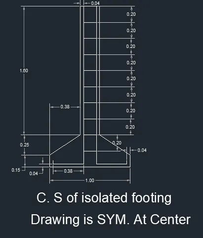
Give the dimensions as per the drawing using dimension command from the command bar. The C.S of the isolated footing is completed |
 |
PART V: ISOMETRIC VIEW OF STEPS
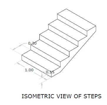
The step by step procedure for drawing isometric view of steps is as follows.
PROCEDURE:
Type DS in the command line and press enter.
Unpick snap on and grid on options
Tick on isometric snap in snap type.
This will activates the isometric screen.
STEP 1
Command: L
LINE
Take isoplane right
Specify first point: anywhere
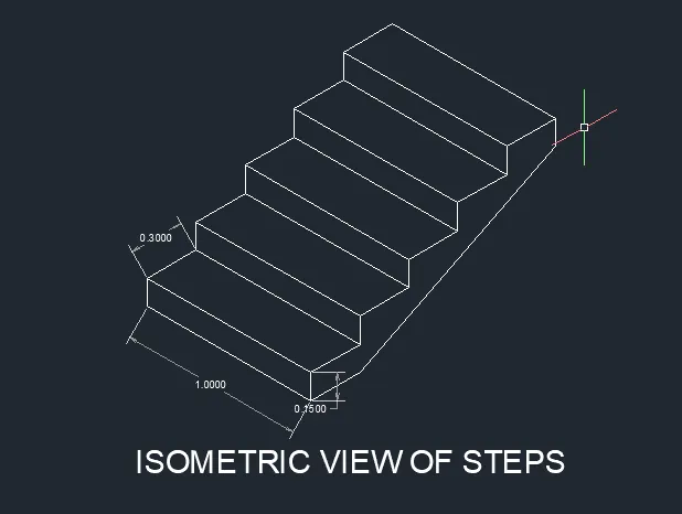
Specify next point or [Undo]: 0.15
Specify next point or [Undo]: 0.30
Specify next point or [Close/Undo]: 0.15
Specify next point or [Close/Undo]: 0.30
Specify next point or [Close/Undo]: 0.15
Specify next point or [Close/Undo]: 0.30
Specify next point or [Close/Undo]: 0.15
Specify next point or [Close/Undo]: 0.30
Specify next point or [Close/Undo]: 0.15
Specify next point or [Close/Undo]: 0.30
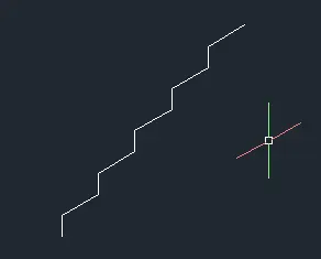
STEP 2
now toggle using function key + f5 key to Isoplane Left
command line L
Specify next point or [Close/Undo]: 1
Specify next point or [Close/Undo]: *Cancel*
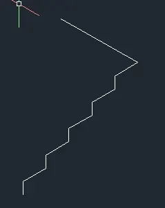
Step 3
Command: COPY
Select objects all the line of steps consisting of line of tread and rise of 0.30 and 0.15 repectively ,
next select base point one side of line of length 1 and paste on other side of the endpoint line of length 1.
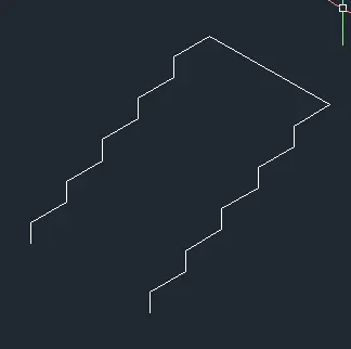
STEP 4
again command CO
select the base point on the top line of length 1 and specify the points where we want to paste it i.e paste it 5 times each time at 0.30 and 0.15 distance.
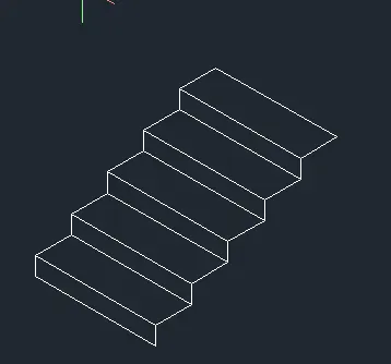
step 5
command line L
toggle to isoplane right
specify a point using cursor right bottom corner point and draw a line of 0.30
now specify a point right top corner point and draw a vertical line of 0.15
Now join this above drawn line together
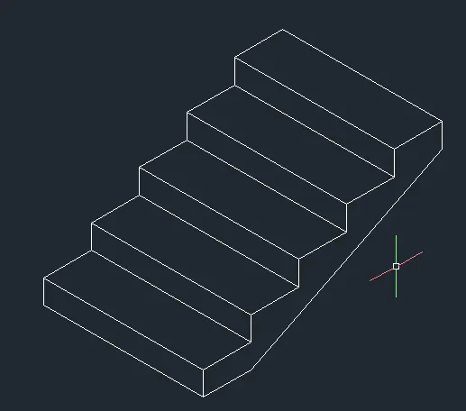
RESULT: Isometric view of steps
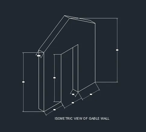
PART VI: ISOMETRIC VIEW OF GABLE WALL
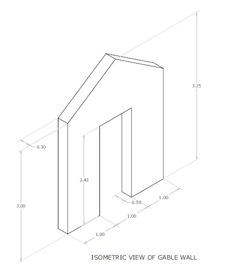
Isometric view of gable wall.
Aim: To draw the isometric view of gable wall.
Commands used:
- Line.
- Isometric plane.
Procedure:
- To work with isometric view -command "ds" - snap off, grid off. put isometric snap on
- Make sure that ortho mode is on
Step:1 - From isometric drafting select iso-plane left.
- Give command "l" and moving the cursor to right give 1 unit
- Pointing the cursor upwards give 3 units
- Draw 0.3 units to left and 3 units downwards and 0.3 units to right.
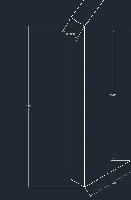
Step:2 - Using isometric right, take line command and draw line upwards of 2.42 units from the starting point of step 1
- Draw 1 unit towards the right and 2.42 units downwards.
- Using isometric left again, using line command draw 0.3 units to left side and draw a line which intersects the top line.
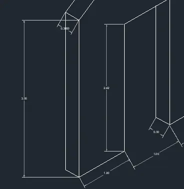
Step 3 – Using iso-metric right with the line command draw 1.0 unit to right Side and 3.0 units upwards.
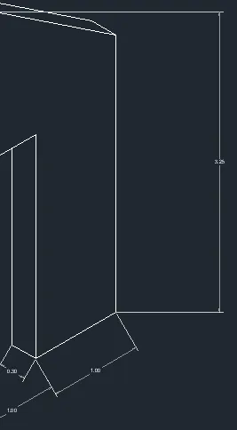
Step:4 - By using the line command draw a line from bottom left corner @1.5 units and extend line 4 units upwards i.e., total 3.25 units from bottom.
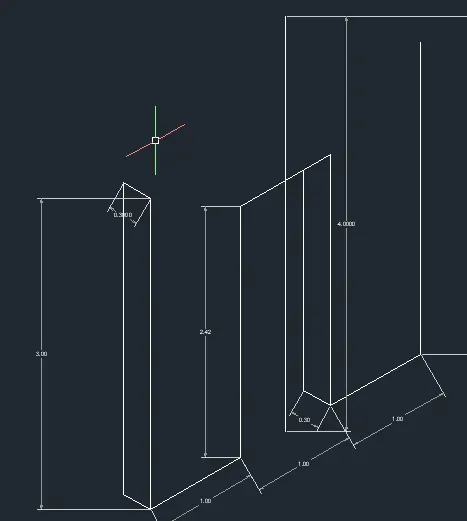
Step :5 - With ortho off, draw a line between the corner of left side and the projected line done in step 4
- Draw it to the other side also till it meets the right corner.
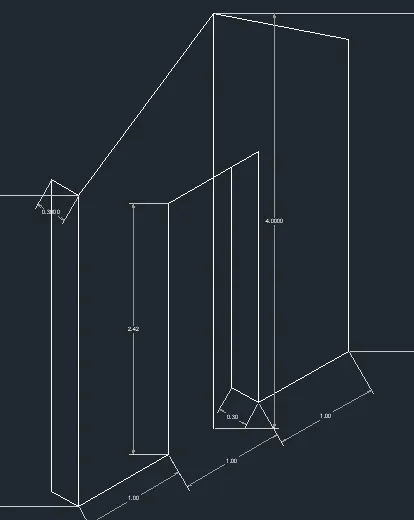
Step:6 - Draw the vertical line with ortho on @0.3 and join the vertical line using line from left and right end same as in the step 5 remove unwanted lines by using erase.
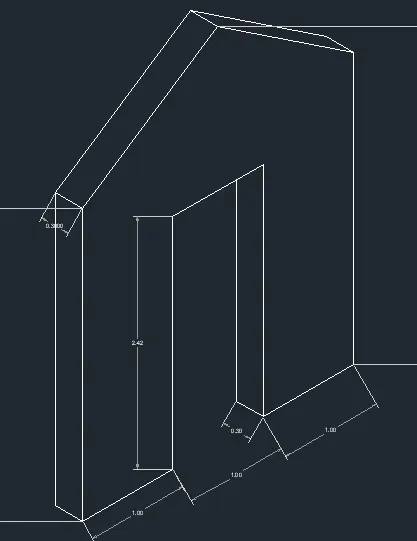
RESULTS : ISOMETRIC VIEW OF GABLE WALL