Creating a Floor plan, Footing detail and Isometric view using AutoCad
AIM: - To draw Floor Plan, section of Isolated Footing, Section of Load Bearing Wall over Stepped footing and Isometric View of Staircase and Gable wall.
INTRODUCTION: - In this project we will draw Section of Load Bearing Wall over Stepped footing, Cross section of Isolated Footing, Section of Load Bearing Wall showing Foundation Details, Line Diagram of Two room Building, Isometric View of Steps, Isometric View of Gable wall. We will use LINE tool to draw these with the help of Direct Distance Entry method and relative coordinate method. The Direct Distance Entry Method is very easy and quick as the tedious work of identifying coordinates of each point gets eliminated. For drawing isometric drawings, we have to turn on the ISODRAFT command from the command tab and draw by switching the ISOPLANES according to the requirements. We will also use different tools such as MIRROR TOOL, TRIM TOOL, ARRAY TOOL, etc to make our work faster and easier
PROCEDURE: - Start the AUTOCAD application and open Imperial template and set the Units as Decimal Units. Simply start the line tool by specifying ‘LINE’ in the command tab.
- Cross section of Load Bearing Wall over Stepped Footing:
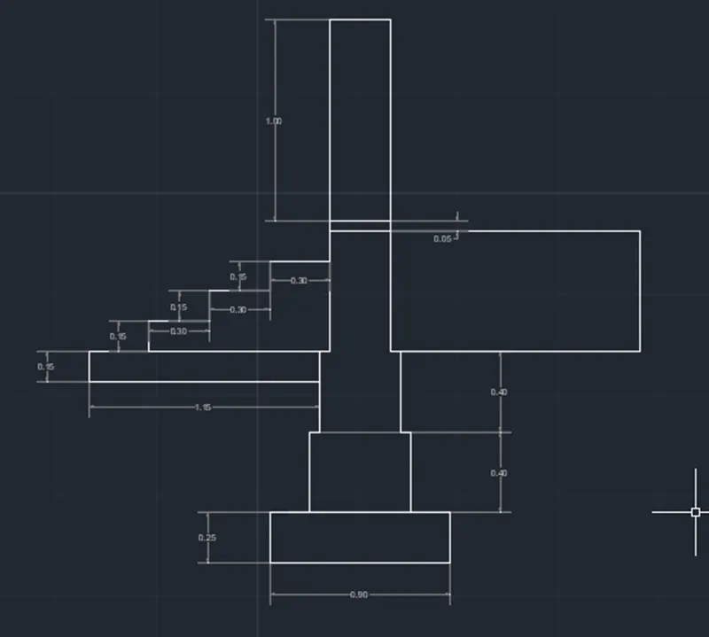
- As we need to draw orthogonally, press F8 key to turn the ORHTO mode ON. Now we can draw only along the axis.
- Start the Line tool by typing ‘LINE’ in the command tab.
- Click on AutoCAD screen to specify the first point of the line.
- Now, keep the cursor in the direction you want to draw the line and enter the distance.
- Keep the cursor in upper direction and enter 0.25.
- Keep the cursor right and enter 0.20.
- Keep the cursor in upper direction and enter 0.40.
- Keep the cursor right and enter 0.1.
- Keep the cursor in upper direction and enter 0.40.
- Keep the cursor right and enter 0.1.
- Keep the cursor in upper direction and enter 0.60.
- Keep the cursor in upper direction and enter 0.05.
- Keep the cursor in upper direction and enter 1.0.
- Keep the cursor right and enter 0.3.
- Again, draw line from point 1 to point 24.
- Now, select all the entities from point 1 to 12 and use mirror command by typing ‘MI’ in command tab. Now, click on the midpoint of line 12 – 13 and drag the mouse to the midpoint of line 1- 24.
- Now, start LINE command again and draw line from point 6 keeping the cursor left and enter 1.15.
- Keep the cursor in upper direction and enter 0.15.
- Keep the cursor right and enter 0.3.
- Keep the cursor in upper direction and enter 0.15.
- Keep the cursor right and enter 0.3.
- Keep the cursor in upper direction and enter 0.15.
- Keep the cursor right and enter 0.3.
- Keep the cursor in upper direction and enter 0.15.
- Keep the cursor right and enter 0.3.
- Press ESC to close the line tool and start again by typing LINE in command tab.
- Specify the first point of line as point 11 and draw a line specifying 0.3.
- Close the line tool and start again and specify the first point as 10 and draw line by entering 0.3.
- Keep the cursor right and enter 1.5.
- Keep the cursor down and enter 0.6.
- Keep the cursor left and enter 1.5.
- Cross section of Isolated Footing
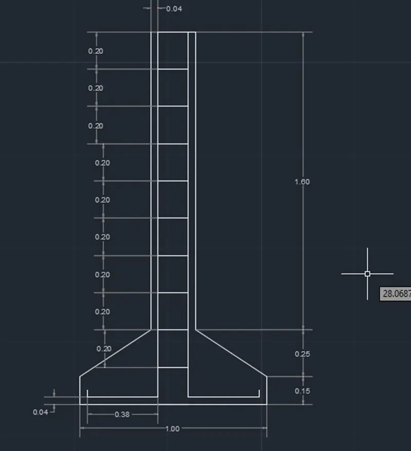
- We will use the Relative Coordinate system to this.
- Identify the coordinates of all the points from the image.
- Start the line tool by typing ‘LINE’ in the command tab.
- Click on AutoCAD screen to specify the first point of the line.Now specify next point as @0,0.15.
- Now specify next point as @0.38,0.25.
- Now specify next point as @0,0.15.
- Now specify next point as @0,1.60.
- Now specify next point as @0.04,0.
- Now specify next point as @0.16,0.
- Now specify next point as @0.04,0.
- Now specify next point as @0,0.15.
- Now specify next point as @0, -1.60.
- Now specify next point as @0,1.60.
- Now specify next point as @0.38, -0.25.
- Now specify next point as @0, -0.15.
- Now specify next point as @ -1.0,0.
- Now we need to draw the reinforcement detail of the column. For this start the line tool again and click on the object snap point at the top of the column art distance of 0.04 from left edge.
- Now specify next point as @ 0, -0.2.
- Now specify next point as @ 0.16,0.
- Now specify next point as @ 0.16,0.
- Now specify next point as @ 0, 0.2.
- Select the last 3 line drawn and copy them by specifying ‘CO’ in the command tab.
- Select the ARRAY option and enter 8 to make 8 copies.
- For drawing the reinforcement of footing, select the bottommost left point of reinforcement and enter @0, -0.16.
- Again, specify next point by entering @ -0.38,0.
- specify next point by entering @ 0,0.04.
- Repeat the procedure for right side reinforcement.
- Line plan of two room building:
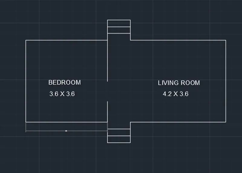
- Start line tool by typing ‘LINE’ in the command tab.
- Press F8 key to turn ORTHO mode on.
- Specify the first point of the line by clicking on the screen.
- Now, specify next point of line as @0,3.6.
- Use OFFSET tool by typing ‘O’ in command tab and enter. Select the line to offset and enter distance as 8.8.
- For drawing horizontal lines joint the extreme ends of both the line using LINE tool.
- Again, offset the first line drawn at a distance of 3.6.
- Now, for making opening for bedroom, offset the horizontal line at 0.9. Again, at 0.9 from the last point.
- Now, trim the extra lines using the TRIM command.
- For drawing the stairs, click on the edge of bedroom walls and specify the next point as @0, -0.3.
- Specify next point as @1,0.
- Specify the next point as 0,0.3.
- Now select the stair lines and use copy tool to copy the stair 3 times.
- Select the stairs and use mirror tool by typing ‘MI’ in the command tab. Join mid points of vertical lines as reference.
4. Section of Load Bearing Wall showing Foundation Details:
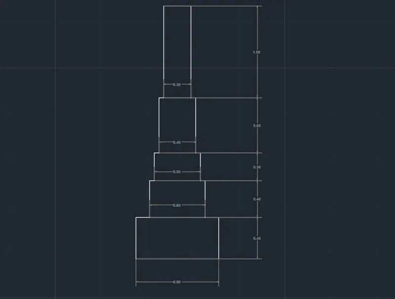
- Start the line tool by typing ’LINE’ in command tab.
- Specify the first point by clicking anywhere on the screen.
- Specify the next point of the line as @0,0.40.
- Specify the next point of the line as @0.15,0.
- Specify the next point of the line as @0,0.40.
- Specify the next point of the line as @0.05,0.
- Specify the next point of the line as @0,0.30.
- Specify the next point of the line as @0.05,0.
- Specify the next point of the line as @0,0.60
- Specify the next point of the line as @0.05,0.
- Specify the next point of the line as @0,1.0
- Now, start the line tool again and click on the starting point of the drawing to specify the first point of the line.
- Specify the next point of the line as @0.90,0.
- Again, close the line tool and start again and draw a line from the topmost point specifying @0.30,0.
- Select all the vertical lines and start the mirror tool by typing ‘MI’ in command tab. Use the midpoint of the topmost and bottommost horizontal line as a reference.
5. Isometric view of stairs:
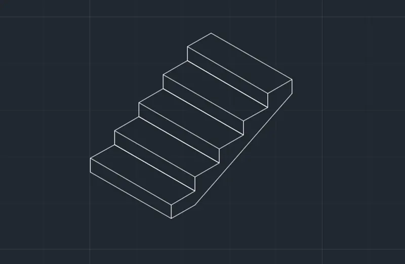
- To draw isometric drawing type ‘ISODRAFT’ and select an isometric plan to start the drawing. You can also switch between the planes by pressing the F5 key.
- Switch to isoplane left, start LINE tool and specify the first point anywhere on the screen.
- Specify the next point by entering distance as 1 and using cursor to give direction.
- Draw one stair and copy it 5 times.
- Now draw a line joining the waist slab.
- Isometric view of gable wall:
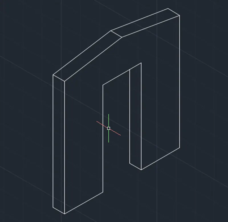
- To draw isometric drawing type ‘ISODRAFT’ and select an isometric plan to start the drawing. You can also switch between the planes by pressing the F5 key.
- Switch to isoplane left, start LINE tool and specify the first point anywhere on the screen.
- Specify the next point by entering distance and using cursor to give direction.
- Now draw a line joining all the edges.
RESULT: - Successfully completed the project drawing Section of Load Bearing Wall over Stepped footing, Cross section of Isolated Footing, Section of Load Bearing Wall showing Foundation Details, Line Diagram of Two room Building, Isometric View of Steps, Isometric View of Gable wall.