Creating a Floor plan, Footing detail and Isometric view using AutoCad
C.S OF LOAD BEARING WALL SHOWING FOUNDATION DETAILS:-
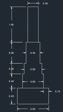
First we make rectangle of 0.9 and 0.45 by using rectangle command.
then make a line of 0.3 with reference of mid point of 0.9 length on upper side of rectangle.
then make line of 0.40 at 90 degree then turn 0.05 towards left and then again turn 0.3 at 90 degree. similarly, turn 0.05 in left direction and then again turn right of 0.60 distance and again turn 0.40 in left direction.
then mirroring the earlier portion by using mirror command to make similar drawing of given drawing.
and then again make line by using line command at the distance of 0.05 on line of distance 0.40,make a line of 1.00 at 90 degree and turn 0.3 towards left direction and then again turn 1.00 in left direction.
then apply dimensions by using dimension linear command.