Creating 3D Isometric view of various structural elements in AutoCAD
ASSIGNMENT NO 13
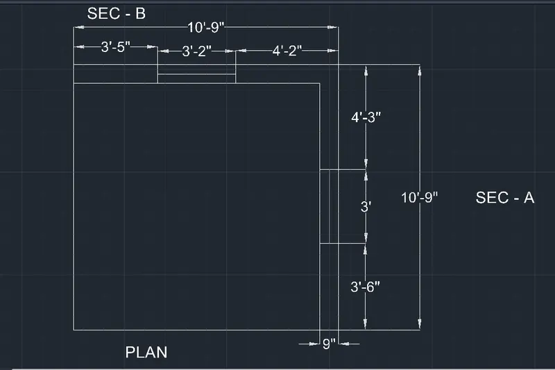
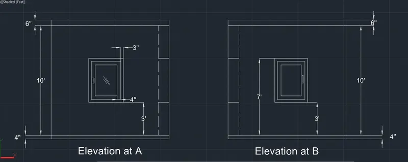
- Create a 3D isometric view of the building with plan and elevation given.
Ans-
Procedure –
Open auto CAD application.
In startup setting start from zero and select the text as feet and inches.
Type UN and press enter.
Set units to scale inserted content as inches and click ok.
Set limits by typing limits in command box.
Change the workspace from drafting and annotation to 3D modeling.
creating plan
Change the current layer to walls.
Type rec command in the command box and press enter.
Click on dimensions in command box.
Specify length of rectangle as 10’9” and specify width of rectangle as 10’9”.
Type o for offset command.
Specify the offset distance as 9”.
Click on the rectangle to specify the object and click inside the rectangle.
Type TR for trim command and trim the left and bottom lines and extend the other lines to edges.
Change the current layer to windows frame.
Type L for line command.
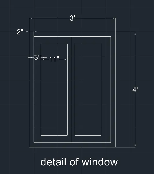
Draw the window with dimensions of 3’2” and 3’ as shown in figure.
Creating 3DView
- Change the view to 3D by clicking on -home" button of view cube.
- Type -BO" in the command
- Create the boundaries for the
- Type -extrude" in the command box and press
- Extrude the boundaries upward at a distance of 10'T0".
- Select all the wall and use group command to group then
- Type -rec" command in the command box and press
- Draw rectangles at both
- Type -BO" in the command box and change the window to
- Type -extrude" in the command box and press
- Extrude both rectangles drown to height of 3'4".
- Type -rec" command in the command box and press
- Draw rectangles at top of both window
- Type -BO" in the command box and change the Drawn rectangles to
- Type -UCS" and click on face and select the face having 3' wide
- Type -rec" command in the command box and press
- Draw a rectangle from bottom port of window with dimensions pS',4'.
- Type -UCS" and click on face and select the face having 3'2- view
- Draw a rectangle from bottom port of window with dimensions p3'2-,4".
- Change the "ucs" back to
- Type -extrude" in the command box and press
- Extrude the rectangle drawn at top view to top edge of
- Group all the wall components
Creating Windows
- Change the current layer to Windows
- Type "UCS™ and click on face and select the face having 3' wide
- Type "rec™ command in the command box and press
- Draw a rectangle of dimension p3”,4".
- Type "O" in the command box and press
- Specify the offset distance as 3-.
- Specify offset object as rectangle and click inside the
- Type -O" in the command box and press
- Specify the offset distance as 4-.
- Specify offset object last offsetted rectangle and click inside the
- Type -BO™ in the command box and press enter and click on pick
- Click inside the window frame area and press
- Type -SUBTRACT" in command box and press
- Select the bigger region and then select the smaller regions to subtract
- Follow the same procedure for all the three
- Create the glass area by the same
- Give dimensions to the window
Creating other Window:-
- Type "UCS" and click on face and select the face having 3'2" wide
- Type "rec" command in the command box and press
- Draw a rectangle of dimension p3”2",4'.
- Type -O" in the command box and press
- Specify the offset distance as
- Specify offset object as rectangle and click inside the
- Type -O" in the command box and press
- Specify the offset distance as 4".
- Specify offset object last offsetted rectangle and click inside the
- Type "BO™ in the command box and press enter and click on pick
- Click inside the window frame area and press
- Type "SUBTRACT" in command box and press
- Select the bigger region and then select the smaller regions to subtract
- Follow the same procedure for all the three
- Create the glass area by the same
- Give dimensions to the window
RESULT -
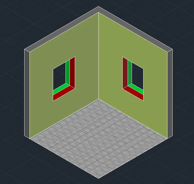
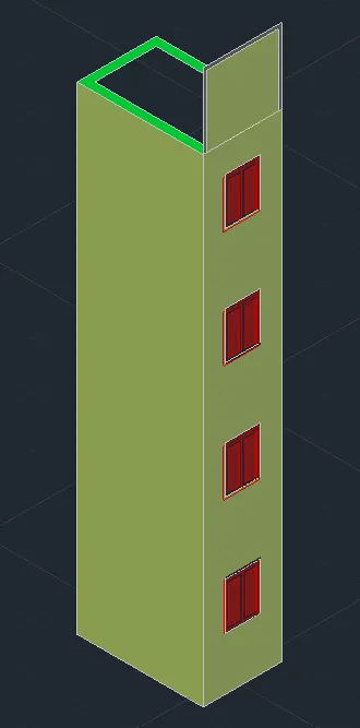
- create the 3D View of the Building Facade as given in the plan and elevation using Auto CAD.
Ans -
Procedure:-
- Open AutoCAD
- In Startup settings start from scratch select Imperial (Feet and Inches).
- Type "Un" and press enter.
- Set Units to scale inserted content as -inches- and click "OK-.
- Sets limits by typing "limits" in command box
- Change the workspace setting of AutoCAD from ”drafting and annotation’ to -3D Modeling-.
- Type -LA- in the command box and press
- In Layer properties manager, create new layers by clicking an new layer
- Add different layers and assign Name, Colours and Line Type to them as follow :—
Creating 2D Plans View
- Type "rec" command in the command box and press enter.
- Click on "dimensions" in command box
- Specify length of rectangle as (6'9“) and specify width of rectangle as (10”9“).
- Type "O" in the command box and press
- Specify the offset distance as 4-.
- Select the rectangle and click inside the rectangle.
- Type 'YR- and press
- Trim the upper edge of the inner rectangle.
- Type "EX" and press
- Extend the side angles of the inner rectangle to the top edge of outer
- Change the current layer Window
- Add dimensions to the
- Create the window opening of dimensions 3’ wide as shown in question
Creating 3D view
Change the view to 3D by clicking on home button of view cube.
- Type "ucs" in the command box and press
- Type W’ and press enter to set the ucs as
- Set the view style control as
- Type 'BD’ in the command box and press
- Create the boundaries for the
- Type "Extrude" in the command box and press
- Extrude the boundaries created to total height of 10’10”.
- select oil the wall and type group and press enter to group the walls
- Delete the window
- Create a boundary region over the window line
- Extrude the boundaries to a height of 4'6“.
- Draw a rectangle on top of the window opening using rectangle
- Change the rectangle into a
- Extrude the region to distance of 1’3" to below and then window opening is created as shown
Change the current layer to window
- Type "UCS" and click on face and select the face having 3‘ wide
Type "rec" for rectangle command and press enter.
Draw a rectangle of dimension 2”,4’.
Type "0" for offset command. Take offset of the rectangle to inside at offset distance of 2".
- Type "0" for offset Take offset of the lost offseted rectangle and click inside at offset distance of 3“. Type "L" for line command and press enter. Draw line connecting midpoints of top and bottom edges at inner rectangle.
- Type "0" for offset Take offset of the line and click both side at offset distance of 3”.
Type OR- and press enter. Trim all the unnecessary edges.
Step 6 :- Creating Views
- Click on home button of the view
- Use zoom command for better
- Go to "view" tab and click on "new view".
- Set view name as View
- Click on current view and click "ok".
- Click on the Front view of the view
- Use zoom command for better
- Go to "view" tab and click on "new view".
- Set view name as View
RESULT -
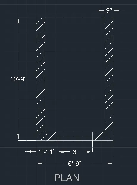
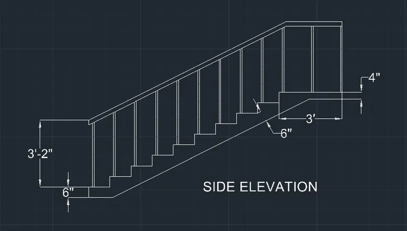
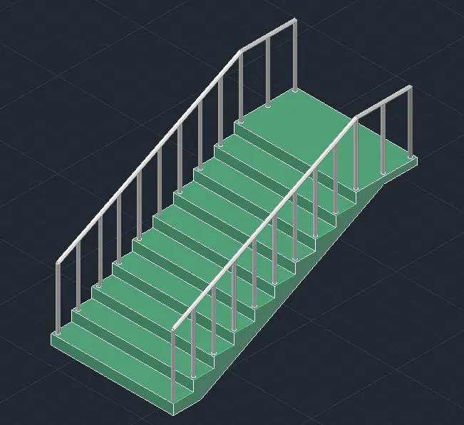
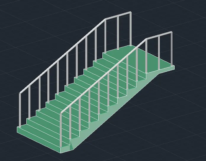
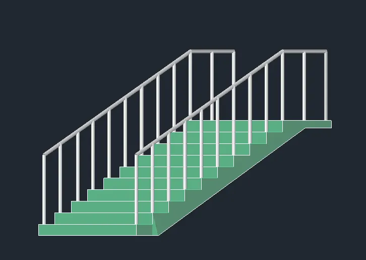
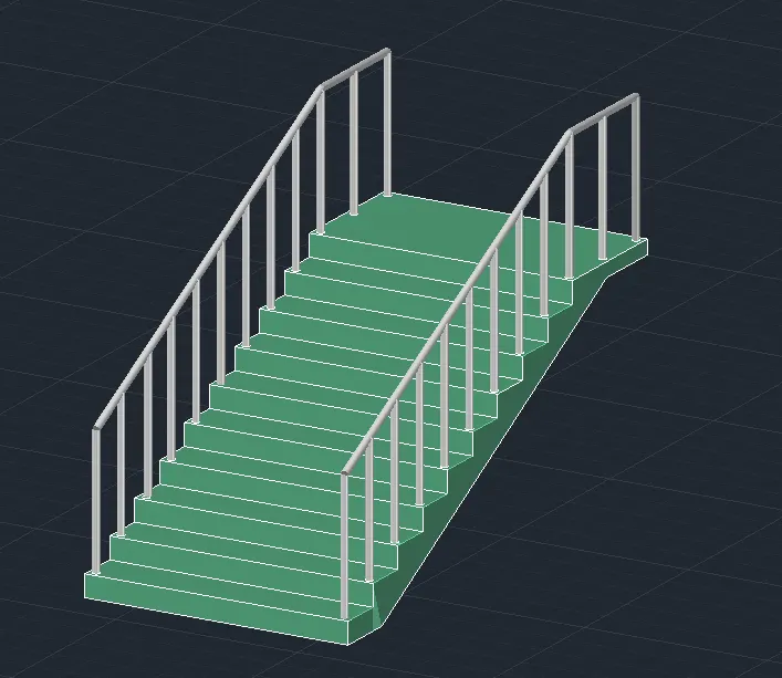
- create a 3D isometric View of a stair with railing with plan and elevation as shown in question Figure using
Ans -
- Open AutoCAD
- In Startup settings start from scratch select Imperial (Feet and Inches).
- Type -Un- and press
Set Units to scale inserted content as -inches- and click "OK-.
- Sets limits by typing -limits- in command box
- Change the workspace setting of AutoCAD term ”drafting and annotation" to -3D Modeling-.
Create a layers
Type "LA" in the command box and press enter.
- In Layer properties manager, create new layers by clicking on new layer
- Add different layers and assign Name, Colours and Line Type to them as follow :—
Creating 2D Plan View at Stair case
- Change the current layer to "Stairs".
- Type -rec" command in the command box and press
- Click on "dimensions" in command box
- Specify length of rectangle as (6’) and specify width of rectangle as (12’).
- Type "explode" in the command box and select the rectangle and press
- Type -O" for offset
- specify the offset distance as 1".
- Select side edges of the rectangle and click inside the
- Type -O" for offset
- Specify the offset distance as 1'.
- Click on the bottom edge of rectangle and make steps by clicking upsides 10
creating Side View
- Change the view to 3d by clicking on home button of view cube and chance the view to right
- Set UCS as Right
- Type -L" for line
- Draw a vertical line of length 6”.
- Continue draw a horizontal line of length 1”.
- Repeat the same process for 10 times to draw 10
- After reaching top
- Draw a landing of length of 3'.
- Press enter to esc line
- Type -L" for line
- Draw a line of 1' at the bottom
- Draw a line of 6- at the top right edge of
- Draw a line of 16-
- Draw a slob joining the
Creating 3D View
- Change the view to 3D by clicking at home button of view
- Type -UCS" in the command box and press enter and type "V and press
- set the view style control as -REALISTIC-.
• Create a region from the side view of the stairs.
- Extrude the side view to a distance of 3”.
Creating Hand Rails
- Change the current layer to
- Draw circle of diameter 1- with 2- offset from the top right edges of the first thread of
- Change the circle into a
- Extrude the region to a height of 3” as shown in the
- Change the current layer to Handrail_
- Draw a handrail stand at the bottom with dimension 2" and
- Change the current layer to
- Draw a polyline connecting all the top edges of
- Change the UCS to front
- Draw a circle of diameter 2- on top of the first
- Create a region of the circle
- Start Sweep
- Select the circle as object to
- Select the polyline drown as path of
- Copy the some to the other
RESULT -
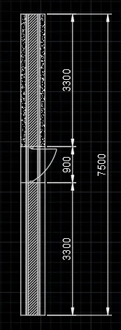
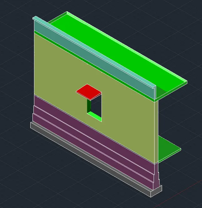
4. create a 3D view and rendered view of a Wall with spread footing with plan and elevations as shown in question Figure using
Ans -
- Open AutoCAD
In Startup settings start from scratch select Metrics (Millimeters).
- Type “Un“ and press
- Set Units to scale inserted content as -inches“ and cIick "OK and Sets limits by typing -limits“ in command bar
- Change the workspace setting of AutoCAD from ‘drafting and annotation‘ to “3D Modeling“.
- Type “LA“ in the command box and press
In Layer properties manager, create new layers by clicking on new layer icon.
- Add different layers and assign Name, Colours and Line Type to them as follow:-
creating 2D Plan View of wall with spread footing
- Change the current layer to
- Type “rec" and press enter and draw a rectangle of dimensions 670mm X 7500mm
- Type “0" and press enter and make offset the rectangle inside at a distance of 120mm
- Type “O“ and press enter and make offset the last offseted rectangle inside at a distance at 5Omm
Explode all the offseted rectangles.
- Delete the top and bottom edges of the exploded
Type “EX' and press enter and extend all the rectangle to tap and bottom edges of outer rectangle.
- At the end, select the individual lines and change their layers
Creating elevation view -
- Click on the Front view of the view cube and use zoom command for better view.
- Change the ucs to
- Change the current layer to "G.L".
Type "L" and press enter and draw a line of certain length.
- Type "O" and press enter and take offset of the line to bottom at a distance of
Type "O" and press enter and take offset of the last offset line at bottom at a distance of I00mm.
- Change the current layer to "Wall".
- Type "rec" and press enter and draw a rectangle of dimension 230mm X 3300mm from the tap left edge of Ground
- Change the current layer to "Roof Level".
- Draw roof of thickness
Draw a Parapet wall of height 600mm.
Footing Layers
Type "rec" and press enter and draw a rectangle of dimension 230mm X 600mm below the floor level. Type "rec" and press enter and draw a rectangle of dimension 330mm X 400mm below the first level. Type "rec" and press enter and draw a rectangle of dimension 430mm x 400mm below the second level.
- Change the current layer to "Footing".
- Type "rec" and press enter and draw a rectangle of dimension 670mm X 300mm, below the third level as shown
in figure
- Type -TR- and press enter and trim the unnecessary edges.
- Change the current layer to "Doors".
- Type "L" and press enter and draw a line along the length of the door of 230mm at the ground
- Type “0' and press enter and take offset of the line to below at a distance of 50mm below the ground
- Type “0' and press enter and take offset of the line at a distance of 2100 to
- Change the current layer to "Door Shade'’.
Draw the door shade as shown in question figure.
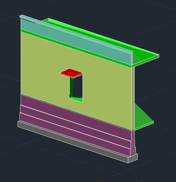
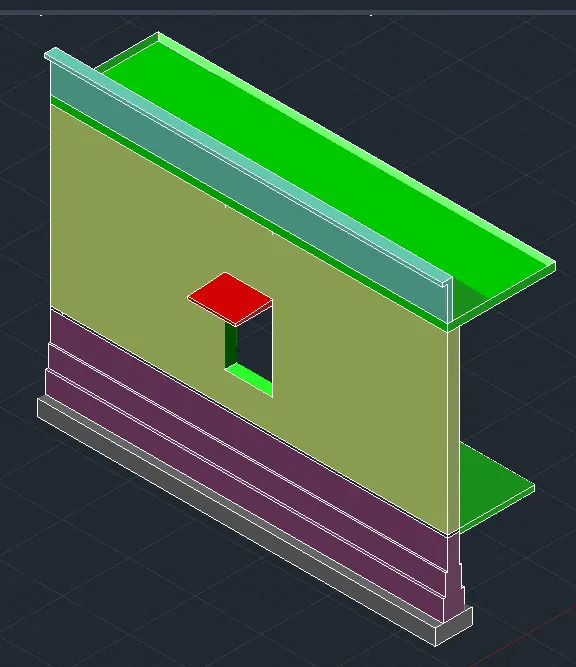
Drawing 3D view of section
- Type "BO" in the command box and press Create boundaries in each of the region.
- Each boundary is created with its respective foyer as current layer as shown in figure below
The created boundaries are to be extruded to a distance of
- select the boundaries by changing their respective current
- Door opening is added by drawing a rectangle at the door location from the plan
Then from the extruded port, door region is subtracted from the wall using "SUBTRACT command.
- Similarly door shade is created with the opening
RESULT -