Modelling Spot-Welds using LS-DYNA
Objective: Perform crash test for a crash box with Beam and Solid spotweld elements, write a detailed report by explaining the results obtained and compare the axial and shear force among beam and solid elements.
Question:
In this assignment, you will model spotwelds for the given assembly of parts and run a crash test similar to the one in assignment 4. Details about spotweld location is in the image below. The yellow line signifies the spotweld directions. You need to use 3-7 spotwelds along this line, in a symmetric manner, before running the simulation
Open the given keyword file in LS PrePost.
Geometry: The two sheet metal parts are meshed with shell elements and will be connected with spotwelds using beam and solid elements in case-1 and case-2 respectively.
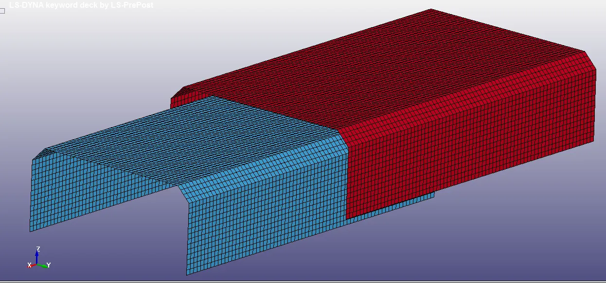
Unit System: gm-mm-ms.
Shell-Thickness: 1.5mm
The crash test is done similarly to challenge 4, so all the cards used in challenge 4 are used same in challenge 5 and some extra cards definitions for spotwelds are used.
Control Termination:

Case-1: Beam Elements (Spotweld)
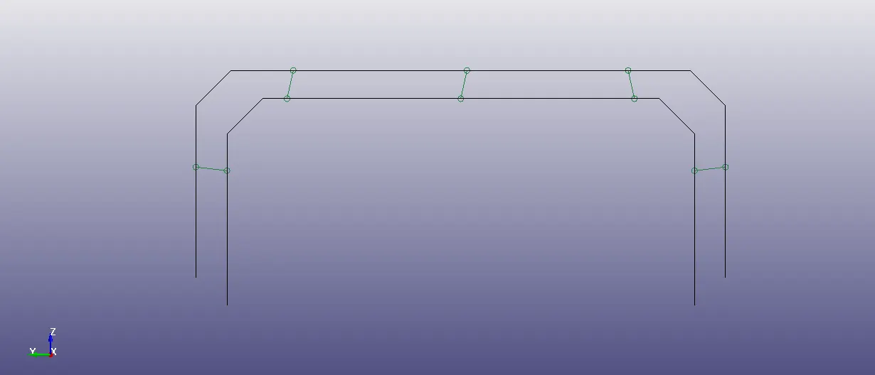
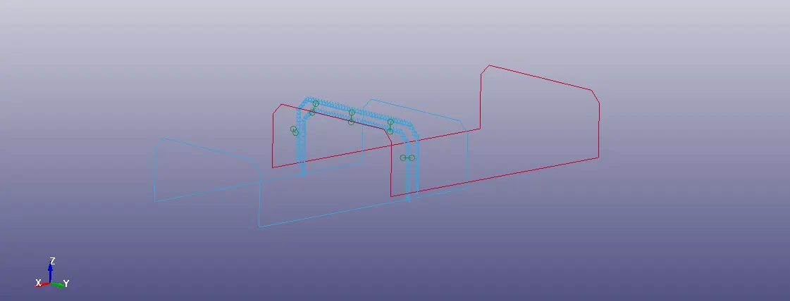
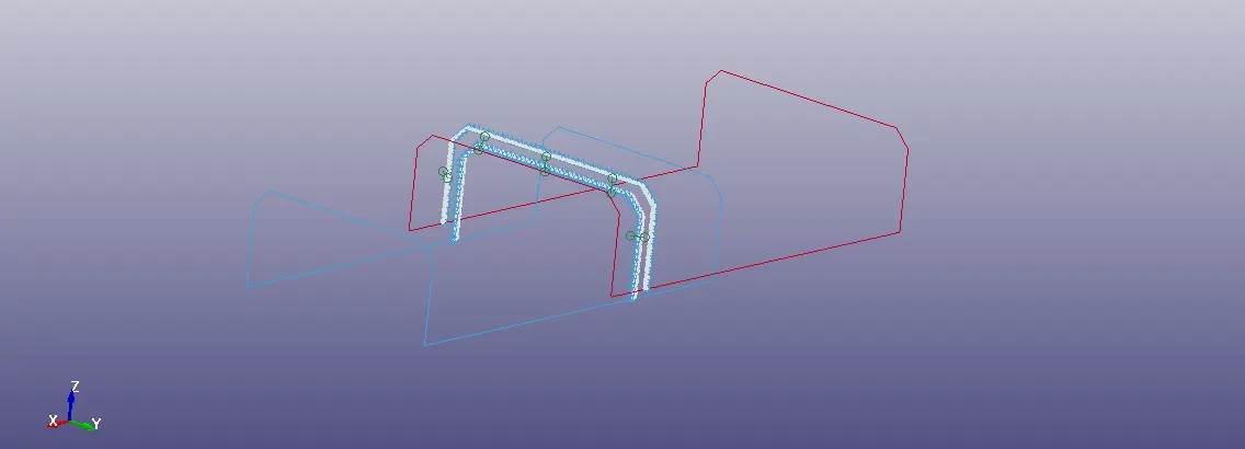
Beam Elements Modelling:
Element Tool>Element Editing>Create>Element Type-Beam>Node-1,2>Accept.
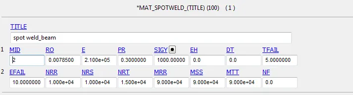
Material for beam element:
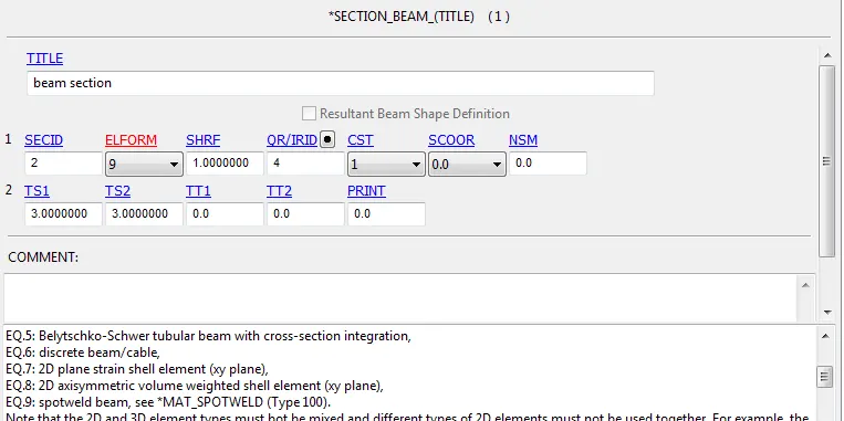
Section for beam element:
The created material and section keywords assigned to the beam element.
Tied Shell Edge to Surface type of contact is used to define spotwelds with spotwelds nodes as slave segment and spotweld part as master segment.
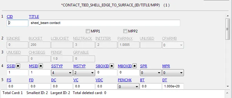
Node set and shell set for cross sectional force.
Post-Processing (Results):
Animation:
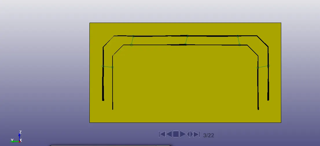
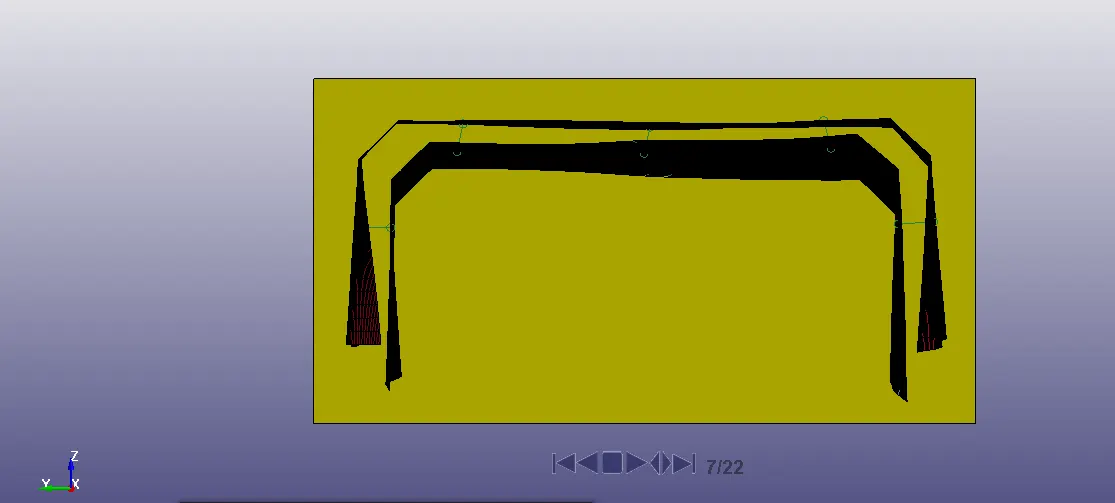
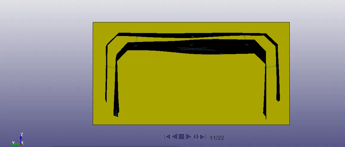
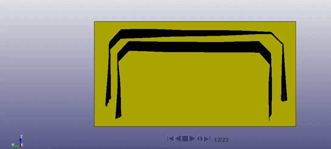
Axial Force:
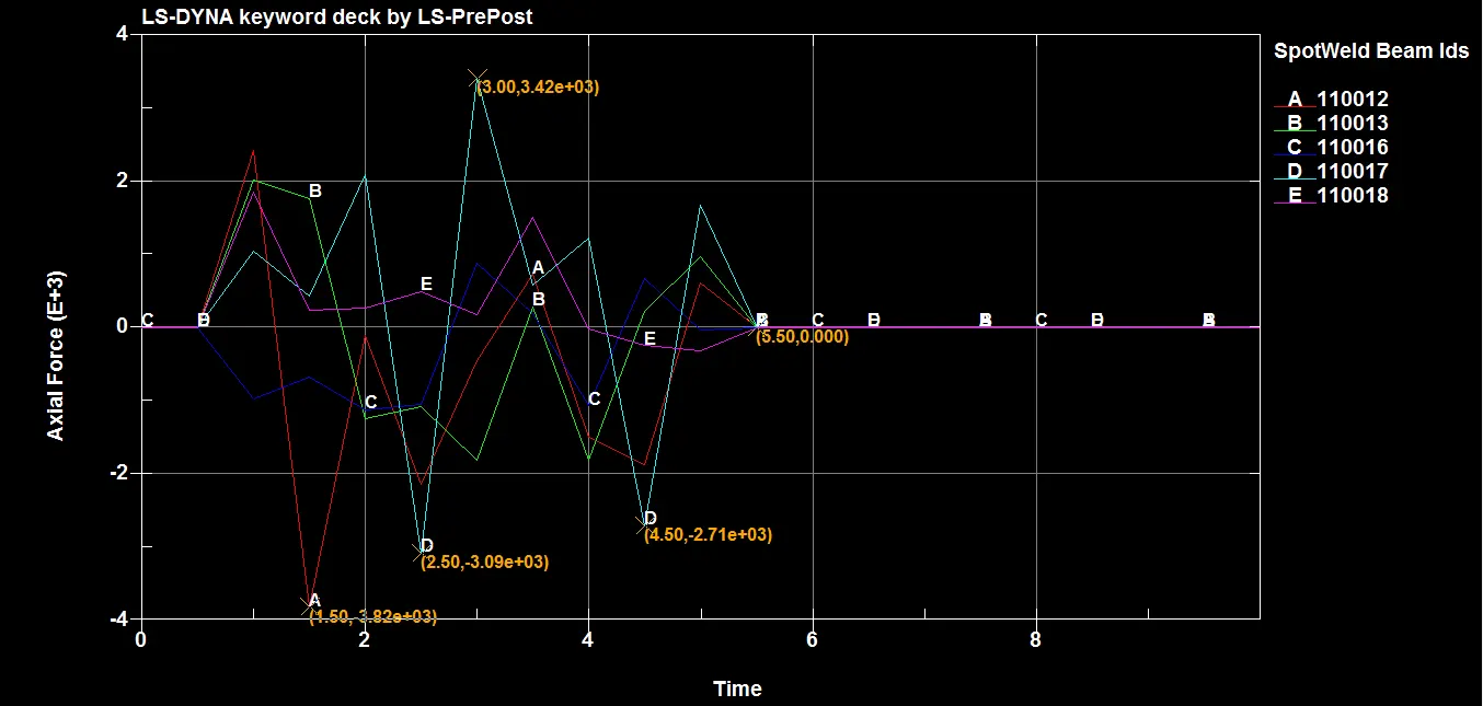
The maximum axial force of 3.82e+3N was experienced by beam element 110012 at 1.5ms.
Shear Force:
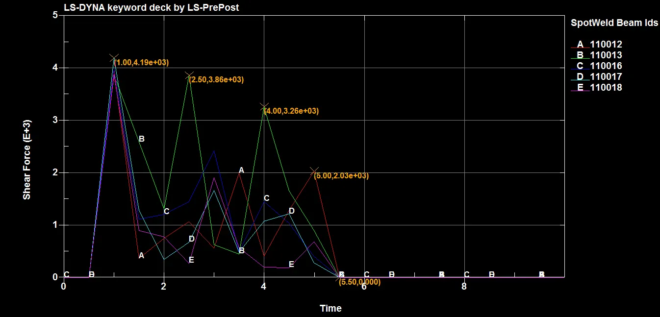
The maximum shear force of 4.19e+3N was experienced by beam element 110017 at 1ms.
Cross-sectional force generated in the middle of the crashbox (along its length):
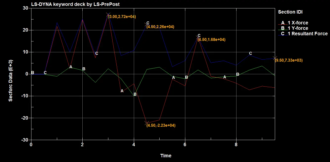
The maximum force at cross section is 2.72e+4N.
Acceleration of a node in the middle of the crashbox:
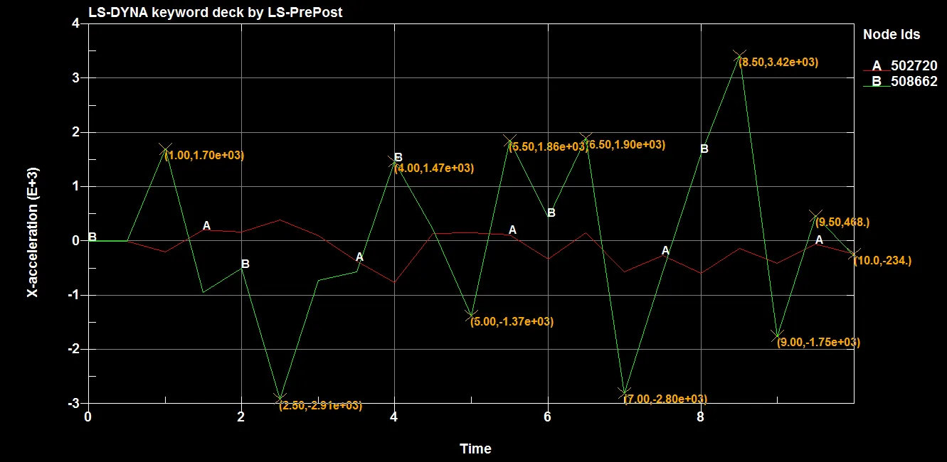
The maximum acceleration of node at mid plane section is 3.42E+03 mm/ms2.
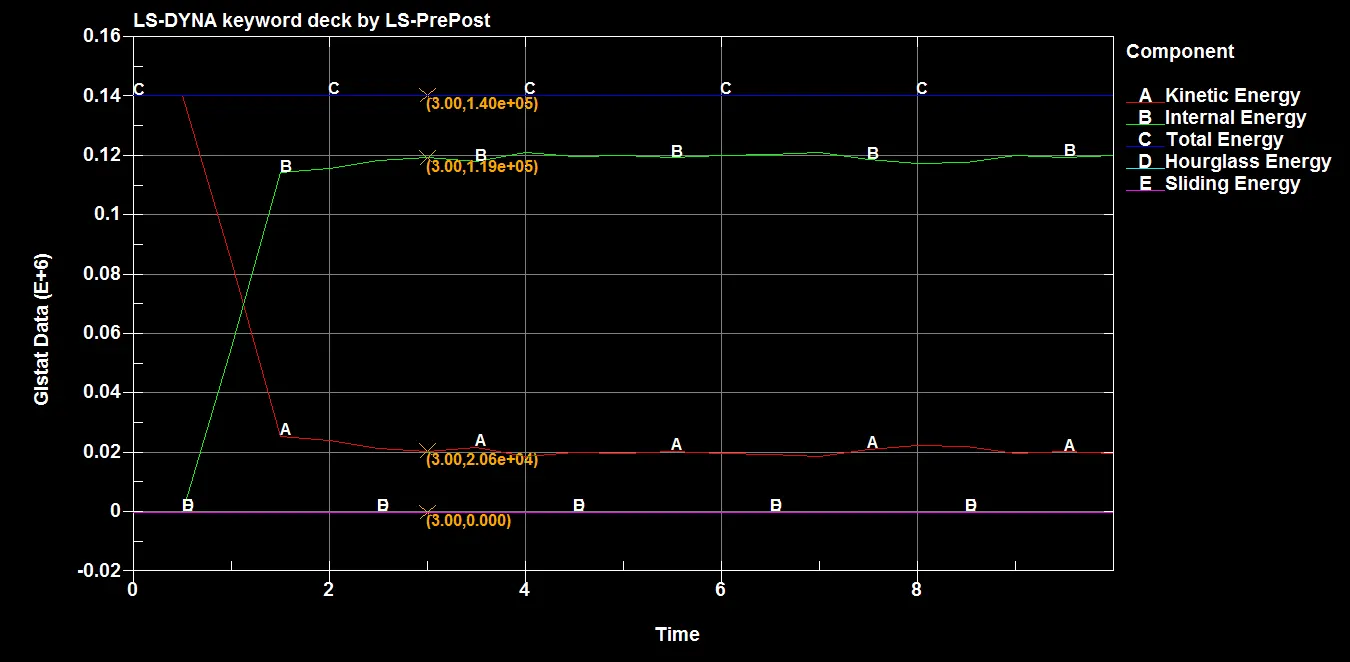
Energy Plots:
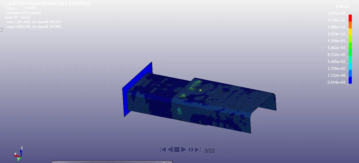
X-Stress:
Maximum: 2424.99 Mpa
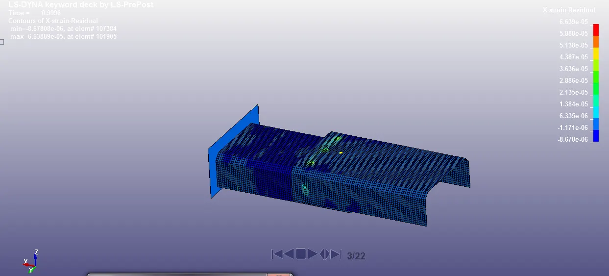
X-Strain:
Maximum: 6.638
Case-2: Solid Elements (Spotweld)
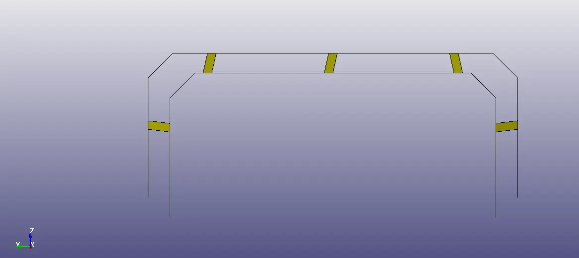
Modelling of solid elements is same as beam elements, just change the element type to (Hex)solid and select the number of nodes to 8.
Material is same as beam element.
Section for Solid element:
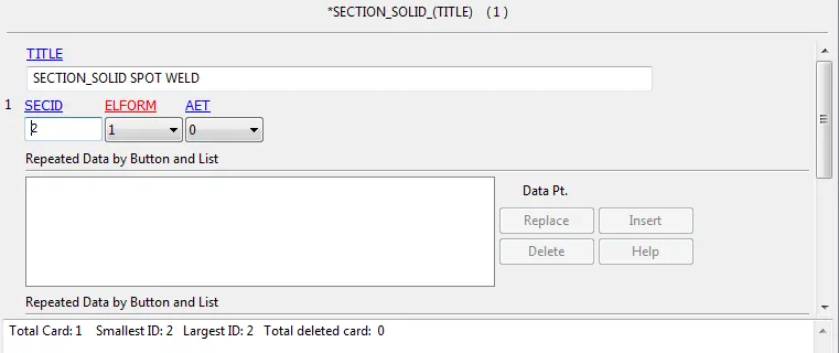
The created material and section keywords assigned to the solid element.
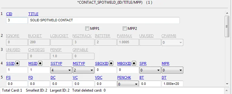
Contact Spotweld type of contact is used to define spotwelds with spotwelds nodes as slave segment and spotweld part as master segment.
Post-Processing (Results):
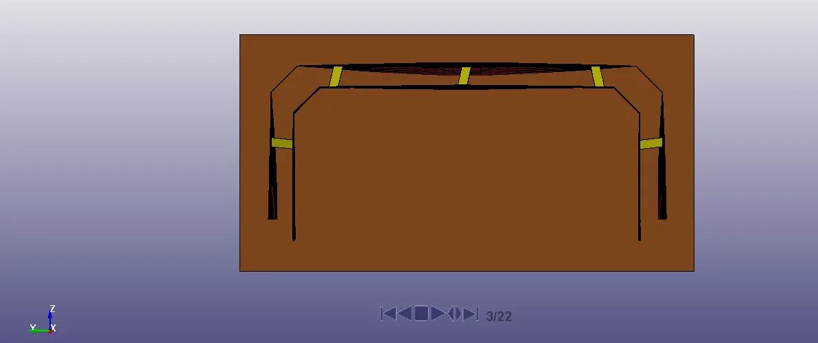
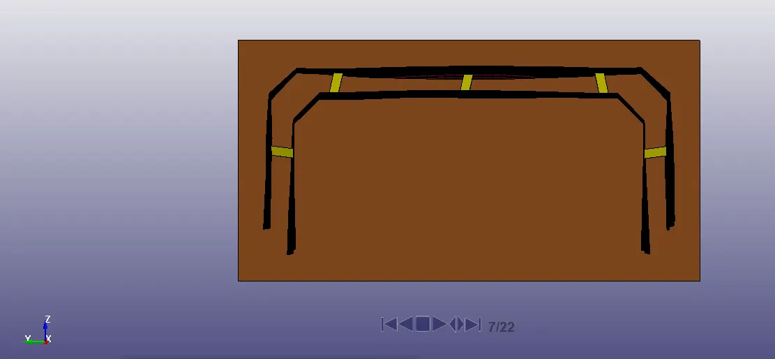
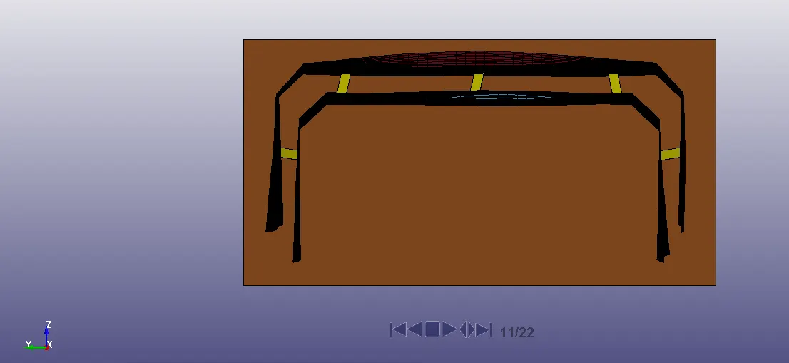
Animation:
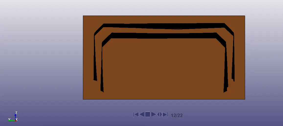
Axial Force:
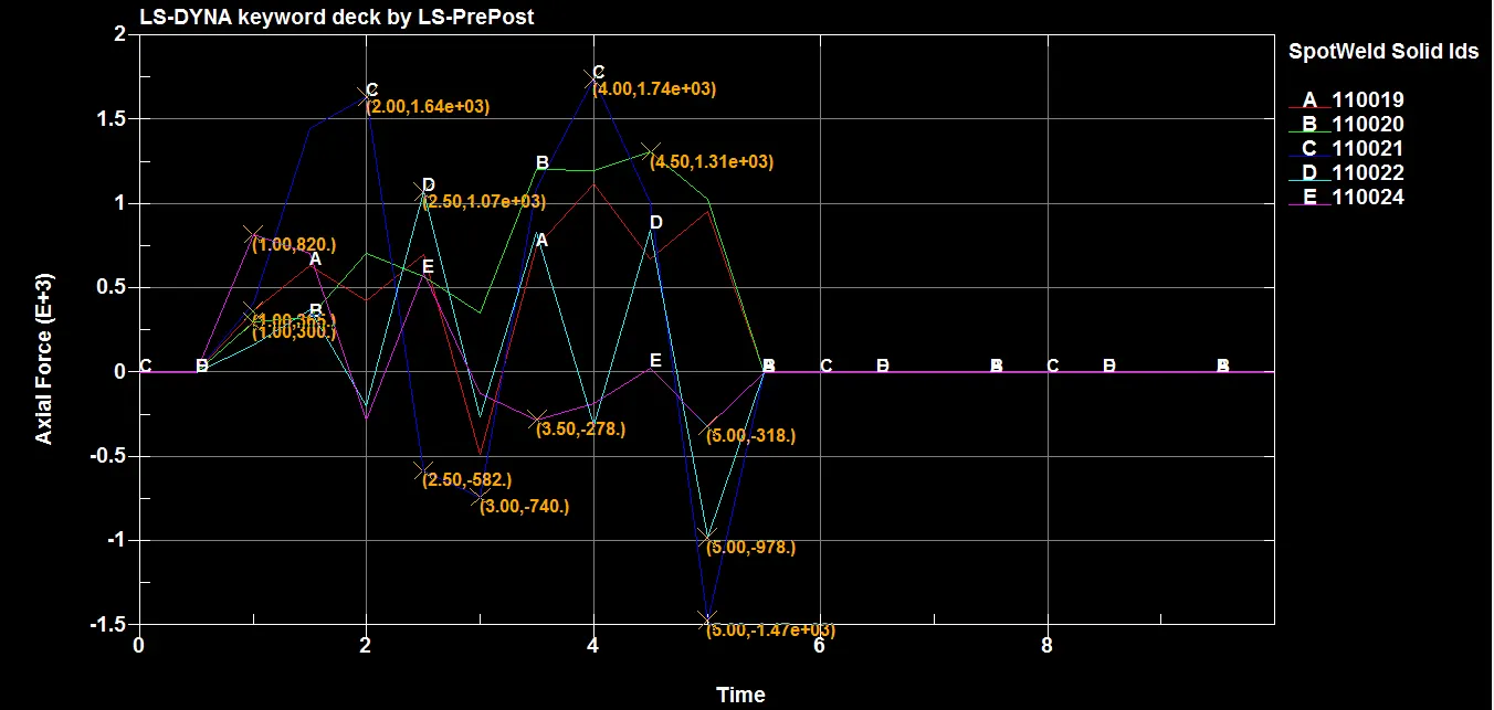
The maximum axial force of 1.74e+3N was experienced by solid element 110021 at 4ms.
Shear Force:
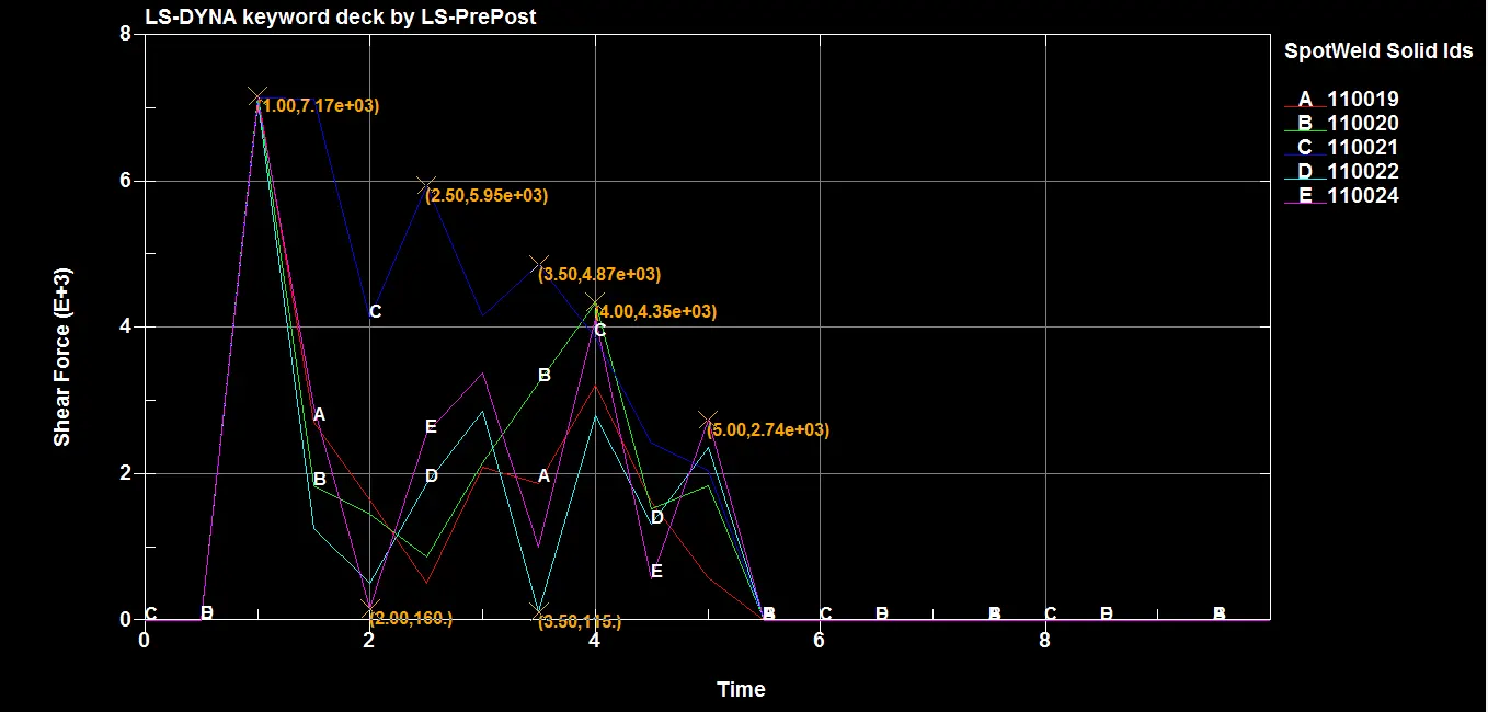
The maximum shear force of 7.17e+3N was experienced by all solid elements at 1ms.
Cross-sectional force generated in the middle of the crashbox (along its length):
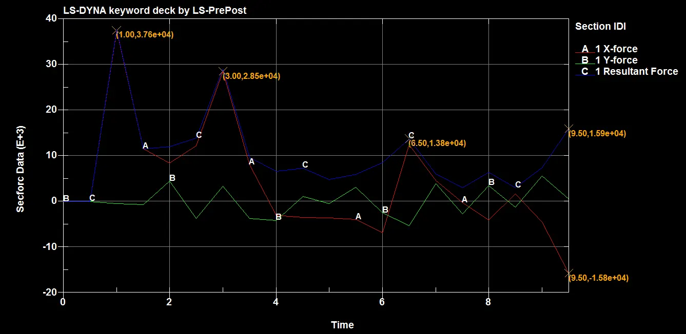
The maximum force at cross section is 3.76e+4N.
Acceleration of a node in the middle of the crashbox:
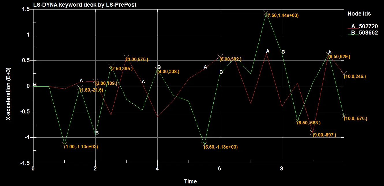
The maximum acceleration of node at mid plane section is 1.44E+03 mm/ms2.
Energy Plots:
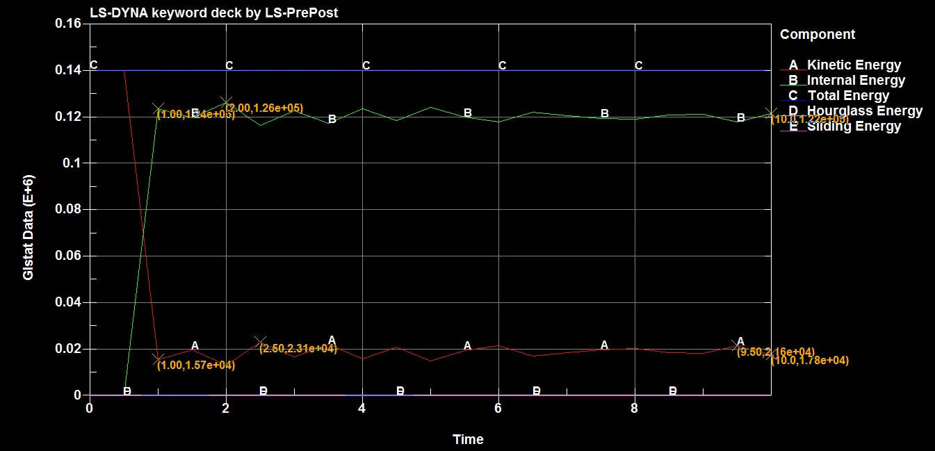
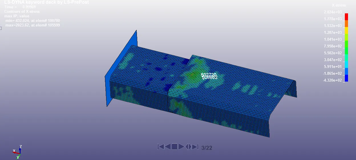
X-Stress:
Maximum: 2023.62 Mpa
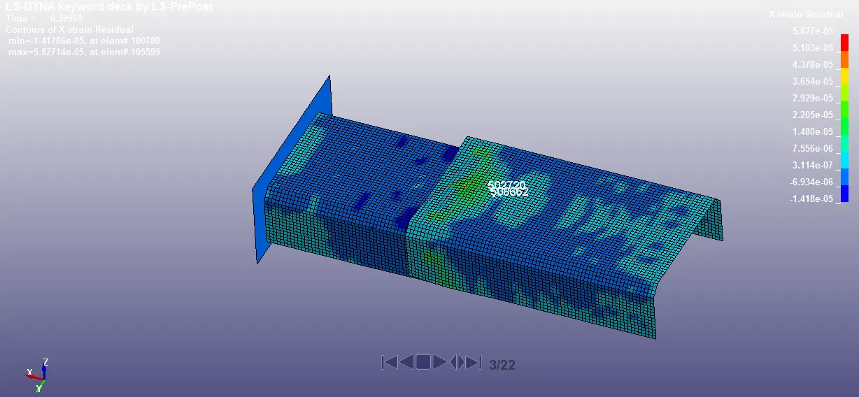
X-Strain:
Maximum: 5.827
Results Comparison & Conclusion:
| S.NO. | Parameter | Beam Element | Solid Element |
| 1 | Axial Force | 3.82e+3N | 1.74e+3N |
| 2 | Shear Force | 4.19e+3N | 7.17e+3N |
- The axial force of beam element is more than solid element because the beam element is a very thin member and have less thickness.
- The shear force is more in solid element as the contact area is more than that in beam element as there is a node to node contact in case-1 as against element to element contact in case-2.
- Solid elements are more preferable as it gives a better representation of the actual spot weld connection.
- The failure of all elements (beam and solid elements) at half of termination time(i.e 5ms) is achieved.
- There is no sliding and hourglass energy as there is no contact between the two parts in both the cases.