Control of DC Motor
AIM-
- Run MATLAB demo ‘Speed control of a DC motor using BJT H-bridge’. Modify the model such that armature current doesn’t shoot up when motor changes direction from forward to reverse.
Procedure-
Transistor-
There are different types of transistors. A very common one is the “bipolar junction transistor” or “BJT”. And it usually looks like this:
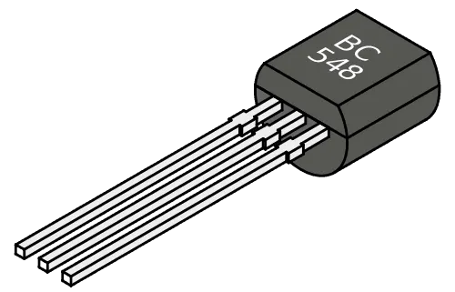
It has three pins: Base (b), collector (c) and emitter (e). And it comes in two versions: NPN and PNP. The schematic symbol for the NPN looks like this:
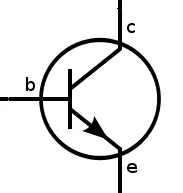
The transistor works because of something called a semi-conducting material. A current flowing from the base to the emitter “opens” the flow of current from the collector to the emitter.
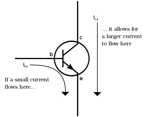
In a standard NPN transistor, you need to apply a voltage of about 0.7V between the base and the emitter to get the current flowing from base to emitter. When you apply 0.7V from base to emitter you will turn the transistor ON and allow a current to flow from collector to emitter.
Speed control of DC motor using BJT H-bridge-
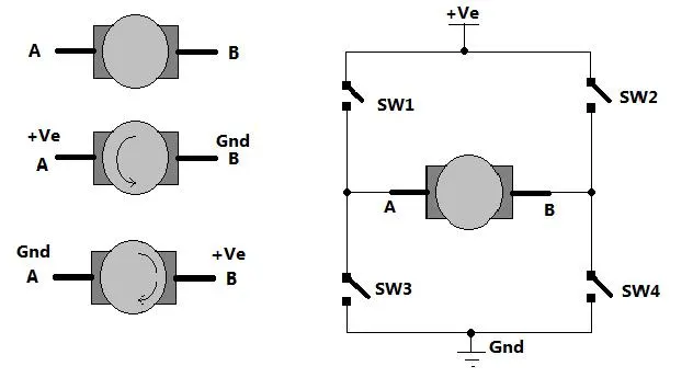
Fig. 1: Image showing H-Bridge circuit used for controlling direction of rotation of a DC Motor
As shown in figure there are two terminals ‘A’ and ‘B’ of DC motor. Now if we connect terminal A with +Ve supply and terminal B with –Ve supply or ground the current will flow from motor from A to B and motor will rotate in one direction – say clockwise (CW) or forward direction. Now as shown in second figure we change the supply terminals. Now B is connected with +Ve and A is connected to ground. The current will flow from motor from B to A and motor will rotate in other direction (counter clockwise – CCW or reverse).
How to give reversible supply to motor?
The arrangement is shown in right side of figure. Four switches are connected in between +Ve supply and ground and DC motor is connected in between two switches as shown. Such circuit arrangement is known as H-bridge because it looks like letter ‘H’ (H-bridge circuits are most widely used in DC motor drivers). Let us see how it gives reverse supply to motor.
If SW1 and SW4 are pressed simultaneously then current will flow from +Ve – SW1 – A – B – SW4 – Gnd. So motor will rotate in one direction. Open (release) SW1 and SW4 to stop motor. Now if SW2 and SW3 are pressed current will flow from +Ve – SW2 – B – A – SW3 – Gnd. So motor gets reverse supply and it will rotate in another direction.
Simulink model-
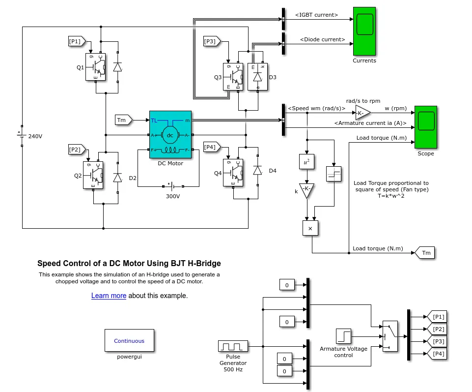
The Bipolar Junction Transistor (BJT) when used for power switching applications, operates as an IGBT. When it is conducting (BJT operating in the saturated region), a forward voltage Vf is developed between collector and emitter (in the range of 1 V). Therefore, the IGBT block can be used to model the BJT device.
The IGBT block does not simulate the gate current controlling the BJT or IGBT. The switch is controlled by a Simulink® signal (1/0). The DC motor uses the preset model (5 HP 24V 1750 rpm). It simulates a fan type load (where Load torque is proportional to square of speed). The armature mean voltage can be varied from 0 to 240 V when the duty cycle (specified in the Pulse Generator block) is varied from 0 to 100%.
The H-bridge consists of four BJT/Diode pairs (BJT simulated by IGBT models). Two transistors are switched simultaneously: Q1 and Q4 or Q2 and Q3. When Q1 and Q4 are fired, a positive voltage is applied to the motor and diodes D2-D3 operate as free-wheeling diodes when Q1 and Q4 are switched off. When Q2 and Q3 are fired, a negative voltage is applied to the motor and diodes D1-D4 operate as free-wheeling diodes when Q2 and Q3 are switched off.
After running the results are-
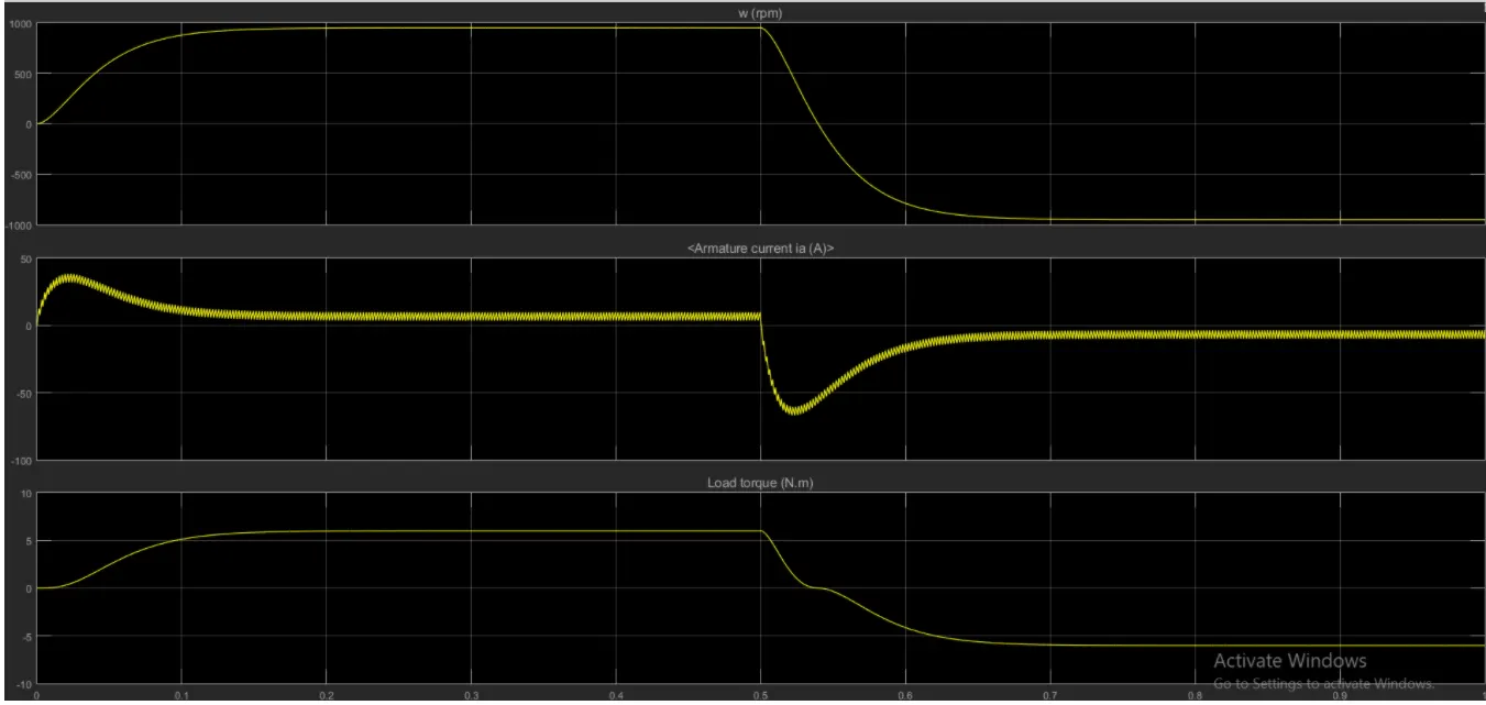
We can see the armature current changes its direction suddenly when the speed of the motor reverses.
Duty cycle-
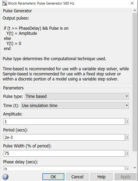
we can see the duty cycle is 75%
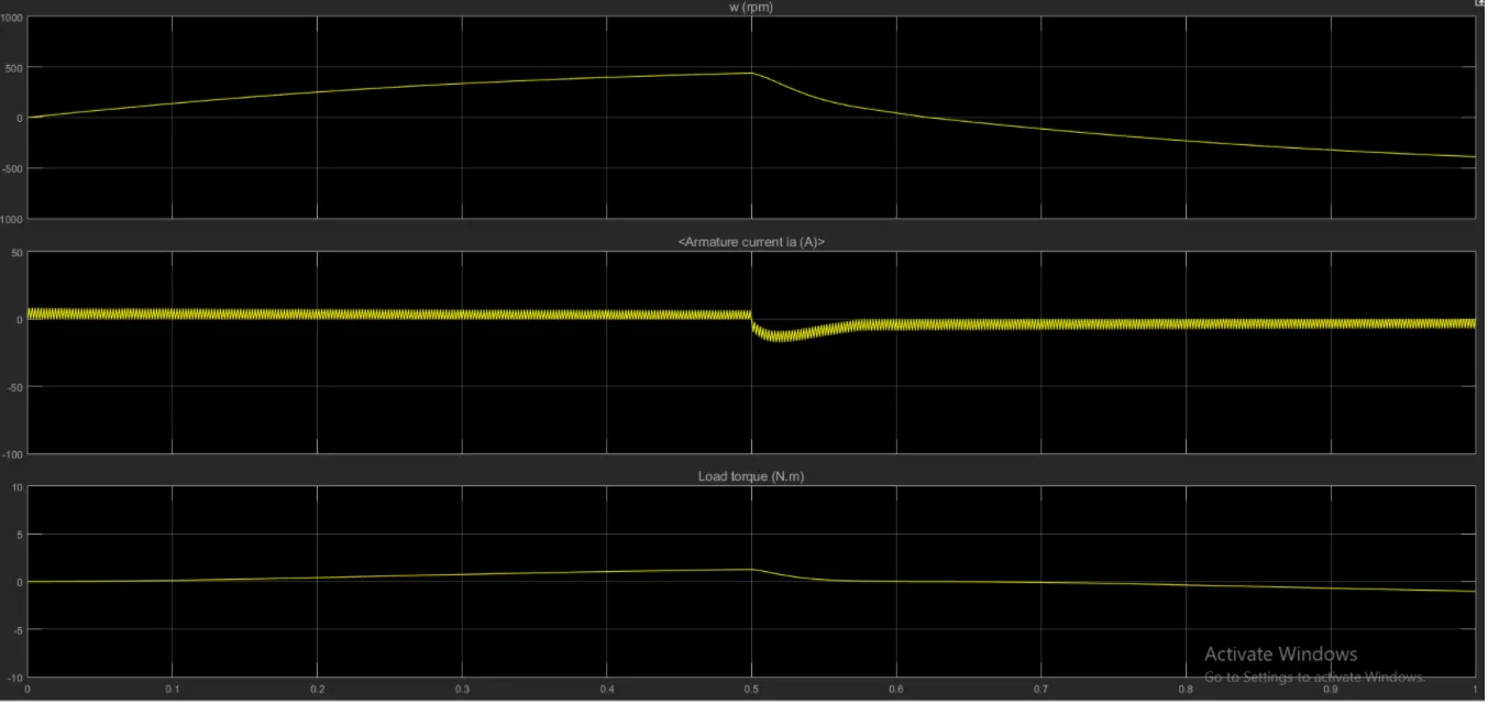
If the duty cycle is changed to 50%
If we furthermore change cycle to 25%
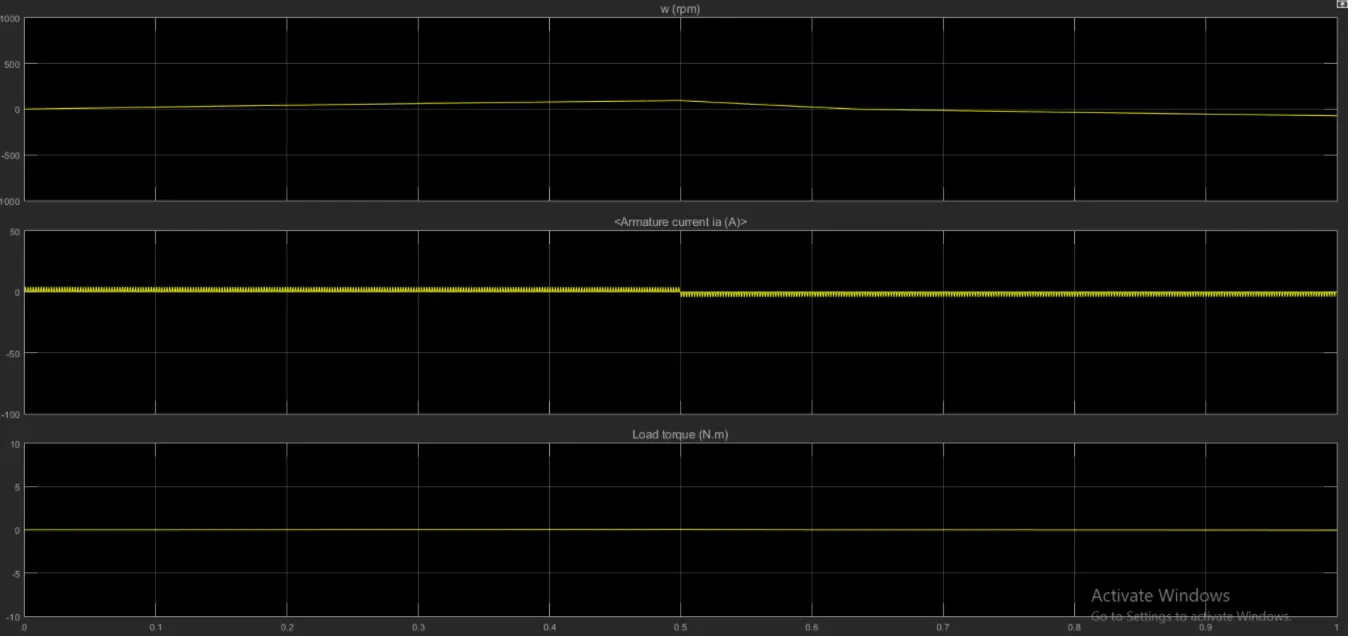
We can see the sudden shoot of armature current is reduced by changing the duty cycle i.e the pulse modulation method.
Study2-
AIM-Refer to help section of ‘The Four-Quadrant Chopper DC Drive (DC7) block’. Compare it with H-bridge model
Procedure-
Four quadrant operation of DC motor-
Four Quadrant Operation of any drives or DC Motor means that the machine operates in four quadrants. They are Forward Braking, Forward motoring, Reverse motoring and Reverse braking.
A motor operates in two modes – Motoring and Braking. A motor drive capable of operating in both directions of rotation and of producing both motoring and regeneration is called a Four Quadrant variable speed drive.
In motoring mode, the machine works as a motor and converts the electrical energy into mechanical energy, supporting its motion. In braking mode, the machine works as a generator and converts mechanical energy into electrical energy and as a result, it opposes the motion. The Motor can work in both, forward and reverse directions, i.e., in motoring and braking operations.
The product of angular speed and torque is equal to the power developed by a motor. For the multi-quadrant operation of drives, the following conventions about the signs of torque and speed are used. When the motor is rotated in the forward direction the speed of the motor is considered positive. The drives which operate only in one direction, forward speed will be their normal speed.
In loads involving up and down motions, the speed of the motor which causes upward motion is considered to be in forward motion. For reversible drives, forward speed is chosen arbitrarily. The rotation in the opposite direction gives reverse speed which is denoted by a negative sign.
The rate of change of speed positively in the forward direction or the torque which provides acceleration is known as Positive motor torque. In the case of retardation, the motor torque is considered negative. Load torque is opposite to the positive motor torque in the direction.
The figure below shows the four-quadrant operation of drives:
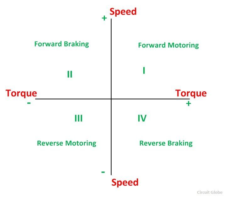
In the I quadrant power developed is positive and the machine is working as a motor supplying mechanical energy. The I (first) quadrant operation is called Forward Motoring. II (second) quadrant operation is known as Braking. In this quadrant, the direction of rotation is positive, and the torque is negative, and thus, the machine operates as a generator developing a negative torque, which opposes the motion.
The kinetic energy of the rotating parts is available as electrical energy which may be supplied back to the mains. In dynamic braking, the energy is dissipated in the resistance. The III (third) quadrant operation is known as the reverse motoring. The motor works, in the reverse direction. Both the speed and the torque have negative values while the power is positive.
In the IV (fourth) quadrant, the torque is positive, and the speed is negative. This quadrant corresponds to the braking in the reverse motoring mode.
Simulink model-
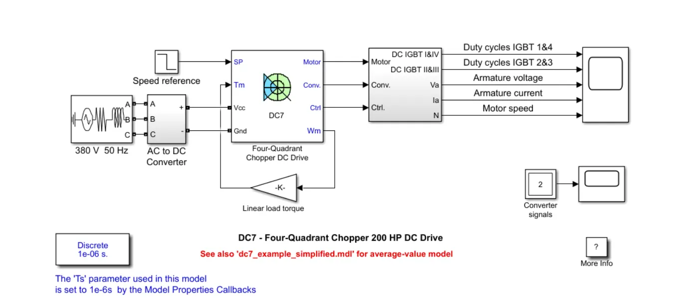
The 200 HP DC motor is separately excited with a constant 150 V DC field voltage source. The armature voltage is provided by an IGET Comverter controlled by two PI regulators. The comverter is fed by a 515 V DC bus obtained by rectification of a 380 V AC 50 Hz voltage source. In order to limit the Dc bus voltage during dynarmic braking mode, a braking chopper has been added between the diode rectifier and the DC7 block .
The first regulator is a speed regulator, followed by a current regulator. The speed regulator outputs the armature current reference (n pu) used by the current controller in order to obtain the electromagnetic torque needed to reach the desired speed. The speed reference change rate follows acceleration and deceleration ramps in order to avoid sudden reference changes that could cause amature over-cument and destabilize the system .
The current regulator controls the armature current by computing the appropriate duty ratios of the 5 kHz pulses of the four IGBT devices (Pulse Width Modulation) For proper system behaviour, the instantaneous pulse values of IGBT devices 1 and 4 are opposite to those of IGBT devices 2 and 3. This generates the average amature voltage needed to obtain the desired armature current. In order to limit the amplitude of the current oscillations, a smoothing inductance is placed in series with the amature circuit.
OUTPUT-
COMPARISON OF FOUR-QUADRANT CHOPPER DC DRIVE (DC7) WITH H-BRIDGE:
In four quadrant chopper DC drive distributes required current supply for each sector and it consist of four quadrants like Forward Motoring, Forward Regenerative Braking, Reverse Motoring and Reverse Regenerative Braking. Whereas H-bridge supplies an irregular current for each sector that causes voltage fluctuation in armature Current. It consist of two operations they are Forward motoring, reverse motoring.
In modern battery charger for electrical vehicles, Hbridge circuits are used. A four-quadrant operation is required in industrial as well as commercial applications.
The efficiency is high in chopper compare with H-bridge, and maintenance is less than H-bridge.
In Robotics Technology, H-bridge circuits are used Some other applications of four quadrant operation is engine test loading systems.
The regenerative braking is not possible in H-bridge while in chopper it is possible .
The most important application of the H-Bridge circuit as the motor driver circuit Hbridge circuits can be placed in small places. Four quadrant chopper is lightweight in nature.
In H-bridge we need to change polarity which turns into opposite direction to control the motor whereas in chopper model we need to interrupt one signal under control of another .
Study 3-
AIM- Make a suitable EV model using DC7 block and make result report.
Procedure-
The armature voltage is provided by an IGBT comverter controlled by two Pl regulators. The converter is fed by a 515 V DC bus obtained by rectification of a 380 V ACSO Hz voltage source In onrder to imit the DC bus voltage during dynamic braking mode, a braking chopper has been added between the diode rectifier and the DC7 block .
The frst regulator is a speed regulator fallowed by a current regulator The speed regulator outputs the armature current reference(in pu) used by the current controller in order to obtain the electromagnetic torque needed to reach the desired speed The speed reference change rate follows acceleration and deceleration ramps in order to avoid Sudden reference changes that could cause armature over-current and destabilize the system.
The energy source of an EV isa battery or fuel cell Let's take the case of a battery To modify the energy source at the input side, you can take agenenc battery model and configure it by referring to any datacheet, sheet related to an EV vehicle battery model Otherwise give any drmving cycle input replacing that input instead of delauht drive oycle By inserting the datasheet with help of drive cycle source block and change the drive cycle source as workspace variable.
A speed reference and time period of duty cycle is obtain from the spreadsheet that are consider as input drrve for EV model Here the circuit model for EV is shown as below.
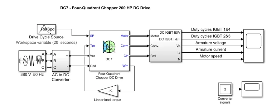
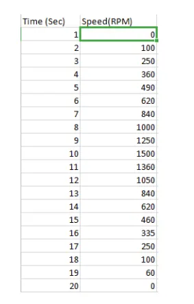
Here we creating a spreadsheet of time and speed of duty cycle in excel format. A unit of time and speed is represented in table The run time is entered up to 20s and speed (RPM) is raised in between that period of time. In this table, the speed is reduced and being stoped at the end of cycle time.
The value of time and speed are assumed and entered in this table are shown as below.
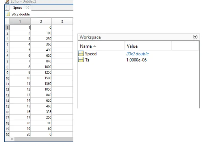
An data from the spreadsheet is imported in Matlab script and taken as drive cycle data for EV model. The data of motor speed and time period is entered in that workspace whereas that data are taken to drive cycle data by Drive cycle source block The speed variation could occur during the cycle time according to the input we are given A workspace table in Matlab is shown as below
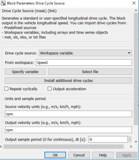
Drive cycle source block is used as speed reference in this EV model where the data is inserted by workspace in matlab. The source velocity units and output velocity units are changed as rpm. Speed reference is consider frorm the drive cycle source and motor speed are obtained from the spreadsheet table The drive cycle source block are shown as below
OUTPUT-
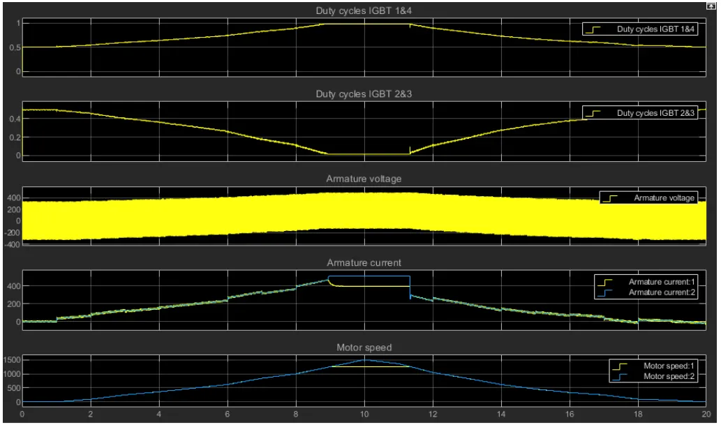
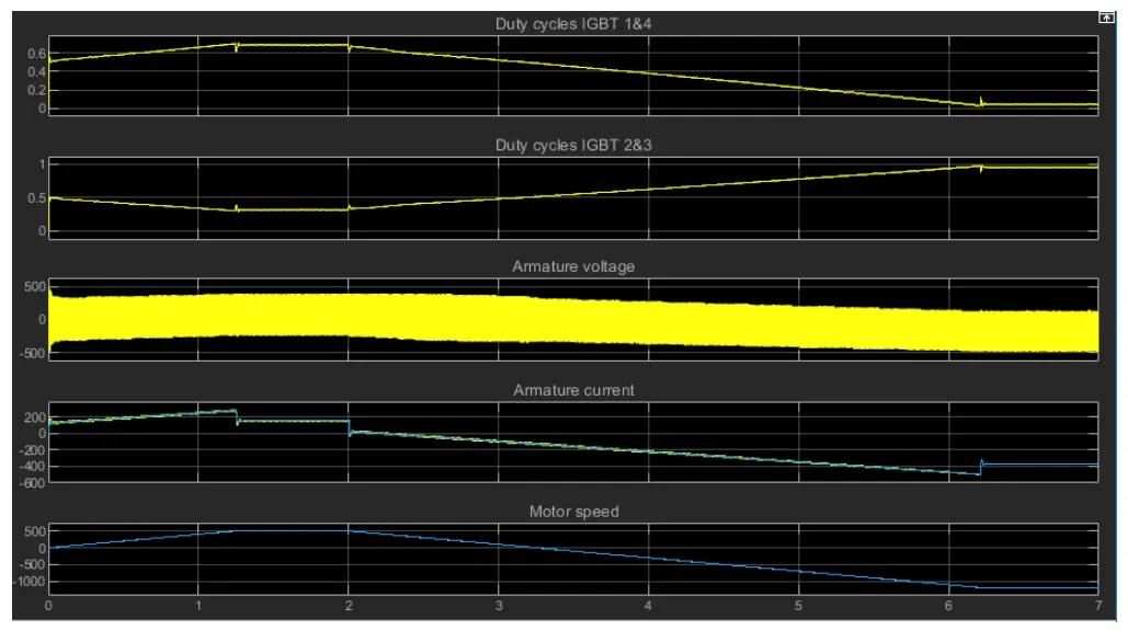
This graphs shows the various low of energy that are armature voltage flow during duty cycle and armature current variations in duty cycle and the motor speed. Duning the 184 duty cycles flow of IGBT current is increased as 80% of the duty cycle this will happen when raise in speed. And it will back to thier actual flow when speed is decreased.
The instantaneous pulse values of IGBT device 1&4 are opposite to those of IGBT devices 2&3. This generates the average armature voltage needed to obtain the desired armature current.
At the duty cycle 283 the inverse action takes place and fiow of IGBT current is passed in a negative direction. It reaches an maximum range of 90% of duty cycle in opposite direction due to increase in speed. When the speed decreases flow of current is low and reaches its actual flow. The flow of armature voltage is passed from negative teminal to the positive terminal.
An armature current obtain from the input data and it may vary according to the speed variation, when the motor speed is increase the current fow in the amature is also increases. Thus amature current increases gradually that depends upon consumption of power supply for drive train. It starts from 0 and flow increases up to 450A of current during the high speed of motor the current will raised. The fuctuation of current is appeared during this operation but minimized the amount of fuctuation is observed in this EV model.
The motor speed is raised in this output graph because of the raise in speed that is entered in the spreadsheet. It reaches 1500rpm of speed in a time period of 10s after that motor speed is decreased and back to its initial state that are mentioned in the drive cycle. Therefore EV model using DC7 block is simulated and results are obtained according to our specified inputs.