Conjugate Heat Transfer Analysis on a graphics card.
Conjugate heat transfer analysis on a graphics card model
Aim:
- Run the simulation by varying the velocity from 1m/sec to 5m/sec for at least 3 velocities and discuss the results.
- Find out the maximum temperature and heat transfer coefficient attained by the processor.
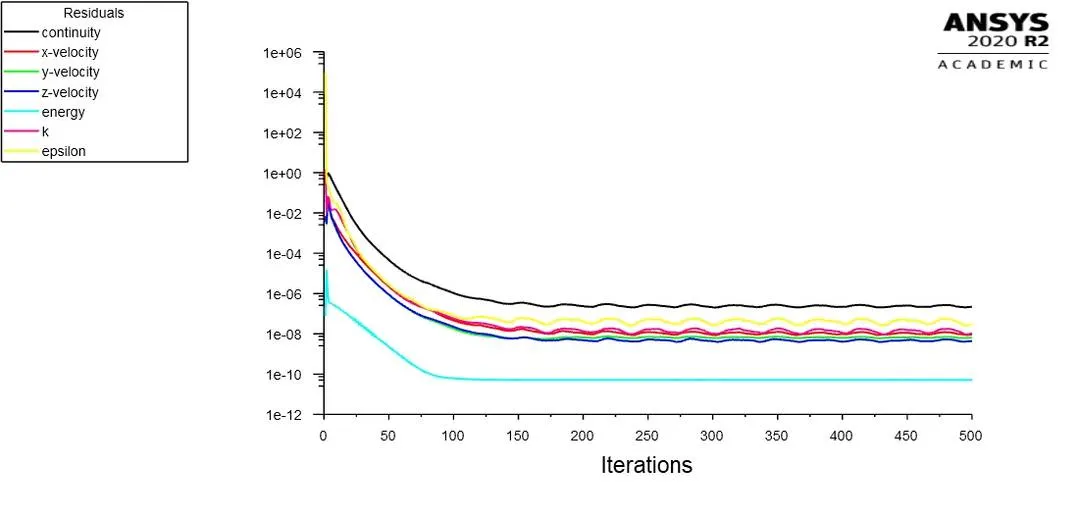
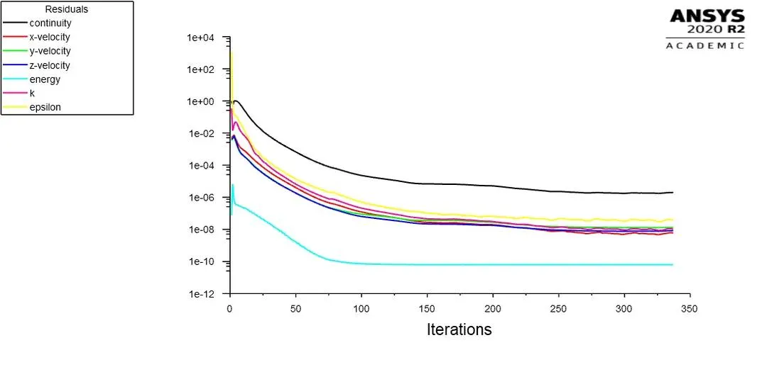
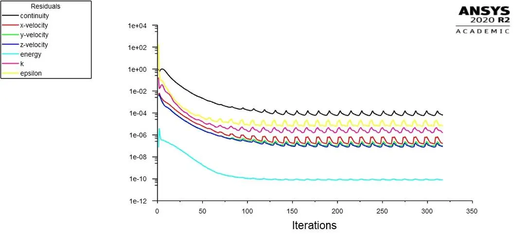
- Prove that the simulation has achieved convergence with appropriate images and plots.
- Identify potential hotspots on the model.
Theory
Conjugate heat transfer corresponds with the combination of heat transfer in solids and heat transfer in fluids. In solids, conduction often dominates whereas in fluids, convection usually dominates. Conjugate heat transfer is observed in many situations. For example, heat sinks are optimized to combine heat transfer by conduction in the heat sink with the convection in the surrounding fluid.
The Conjugate Heat Transfer (CHT) analysis type allows for the simulation of heat transfer between solid and fluid domains by exchanging thermal energy at the interfaces between them. Typical applications of this analysis type exist as, but are not limited to, the simulation of heat exchangers, cooling of electronic equipment, and general-purpose cooling and heating systems.
Procedure:
1. The geometry is opened in Spaceclaim and required interference checks and share topology is done
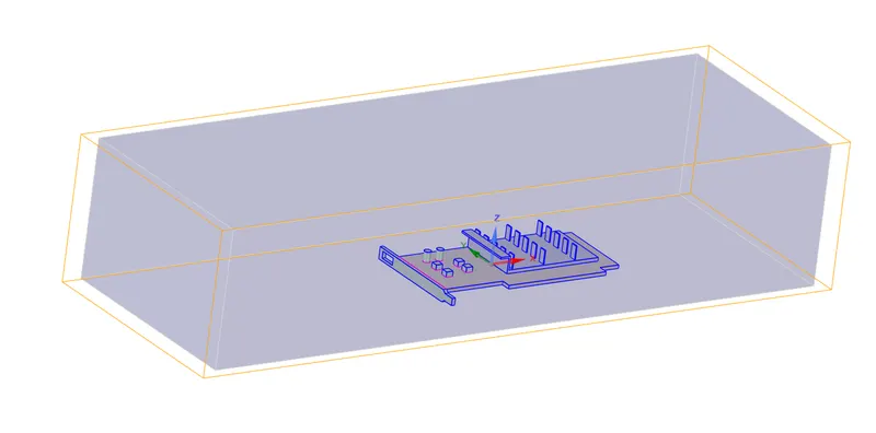
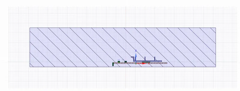
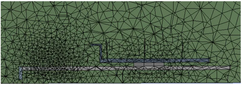
2. Meshing tab is opened and two cases are created with a basseline mesh and a mesh with following properties
Overall mesh = 5mm
Processor and Fins = 0.5mm
Base = 1mm
Coarse mesh
3. Named selection is provided to inlet, outlet and symmetry walls.
Proper naming is provided to interior cell zones of processor, fins and base components.
4. The following solver configuration is used
Steady state simulation
Solver: Pressure based
k-epsilon turbulence model
Materials used :
Fluid = Air
Fins = Aluminium
Processor = User defined silicon material
Base bracket = Steel
Circuit board = User defined silicon material
Solution method: Coupled
Since maximum velocity = 5m/s the Mach number will be less than 1 so we consider incompressible flow.
For the processor an energy source is considered wich is dissipating energy at 2e7 W/m3
Results:
Base Mesh

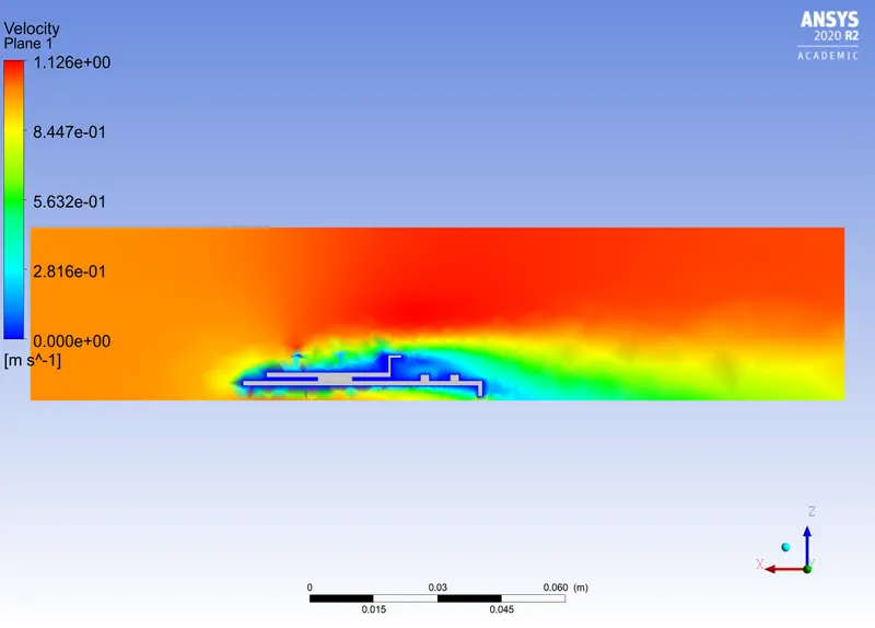
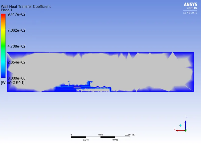
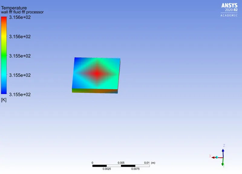
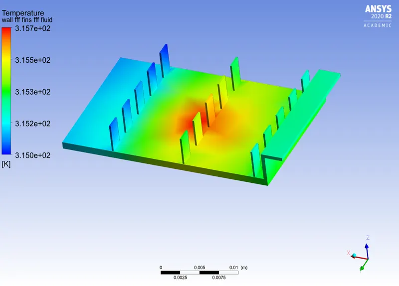
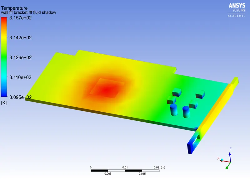
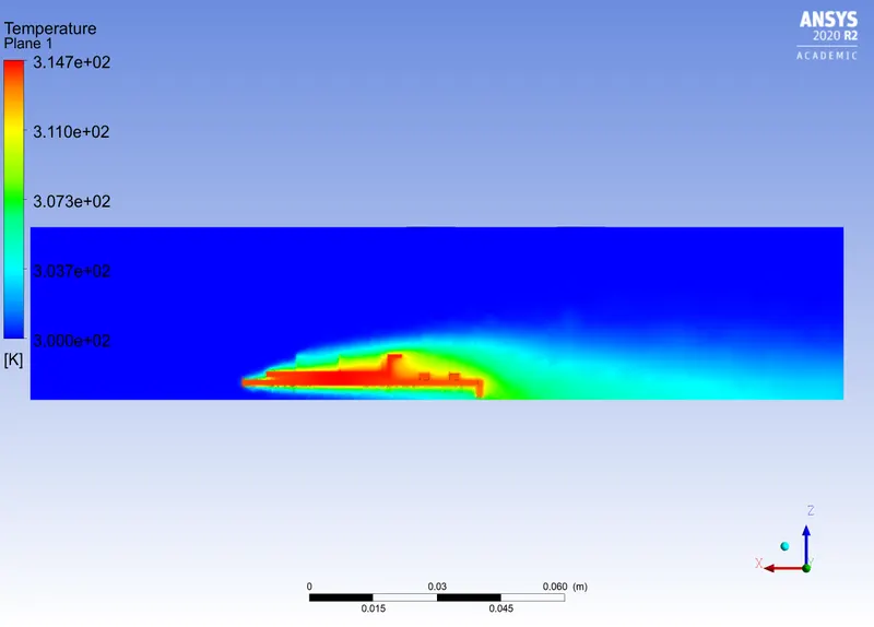
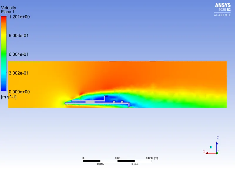
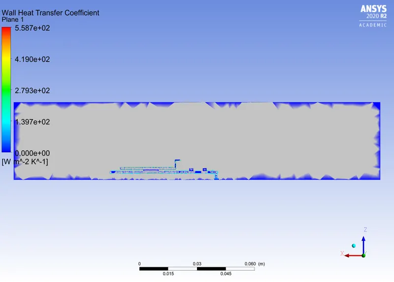
Case 1 : v=1m/s (Refined mesh)
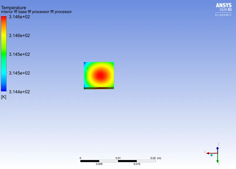
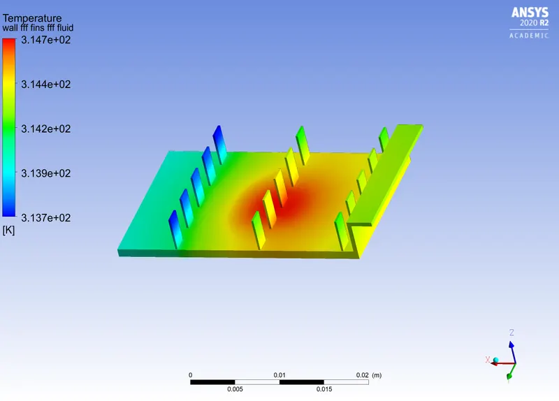
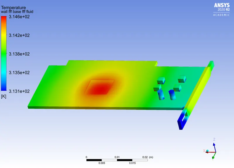
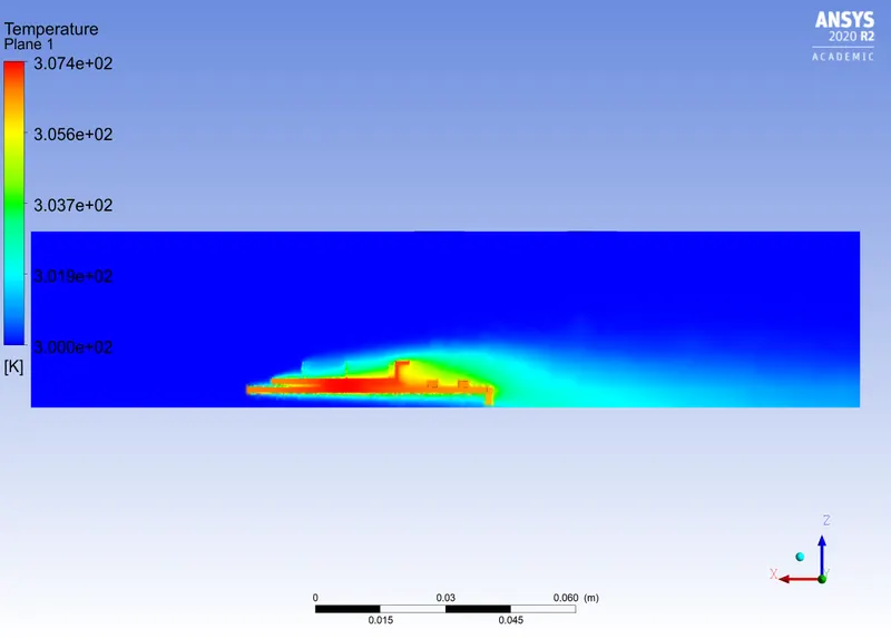
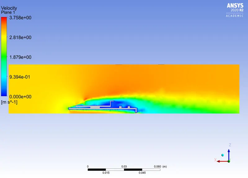
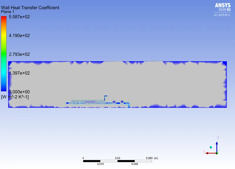
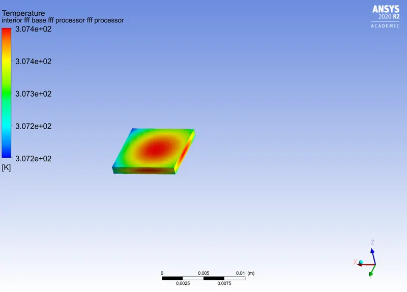
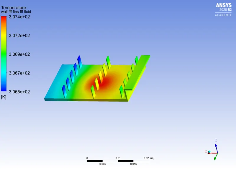
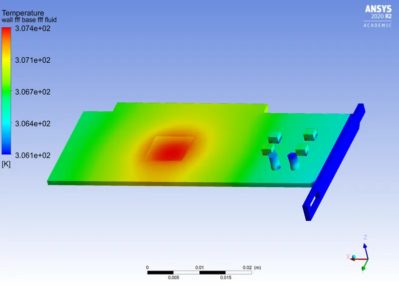
Case 2 : v=3m/s (Refined mesh)
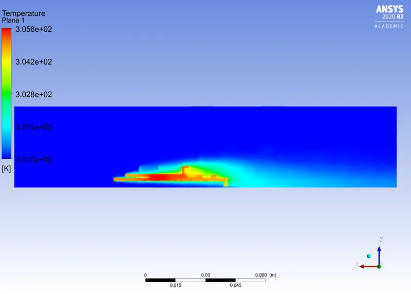
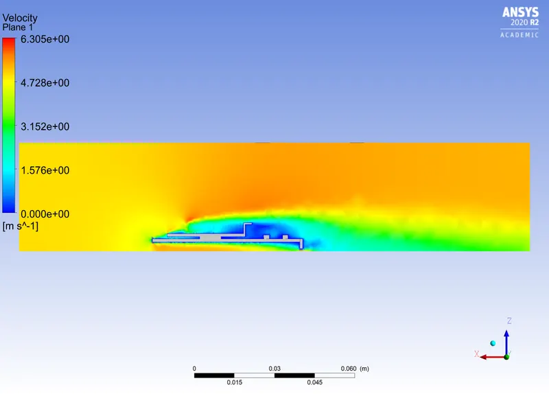
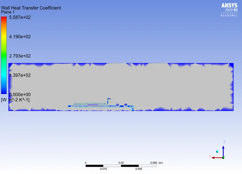
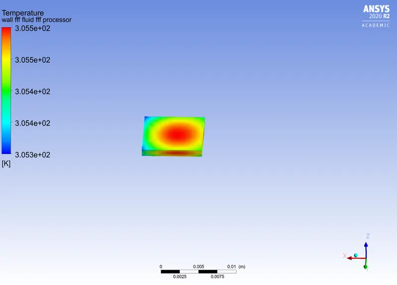
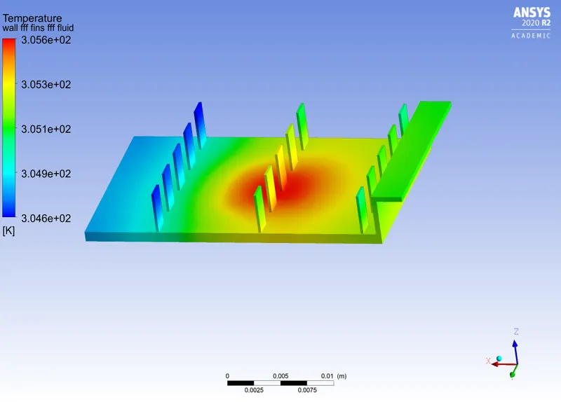
Case 3 : v=5m/s (Refined mesh)
Conclusion:
1. As the mesh is refined better contour values and defenition are obtained. The CHT values in coarse mesh were aeay from the body so the values obtained might be wrong. In case of refined mesh the values are much closer to the wall.
2. The below set of values are obtained
| Case | Inlet velocity(m/s) | Mesh | Max temperature(K) | Max velocity(m/s) | Max heat transfer coefficient (W/m2-K) |
| 1 | 1 | Coarse | 315.7 | 1.126 | 941.7 |
| 2 | 1 | Refined | 314.7 | 1.201 | 558.7 |
| 3 | 3 | Refined | 307.4 | 3.758 | 558.7 |
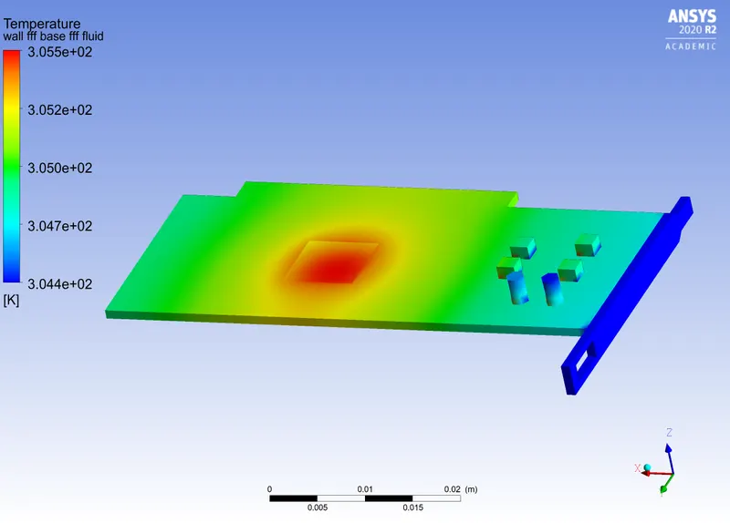
| 4 | 5 | Refined | 305.6 | 6.305 | 558.7 |
3. From above table it is clear that as the inlet fan speed increases the temperature on the graphics card drops. The drop is faster when moving from 1m/s to 3m/s where we can see a drop of 7.3K. When fan speed increases from 3 to 5m/s the temperature drop is only 1.8K.
4. The Heat transfer coefficient does not change as the velocity increases as it is a boundary phenomenon.
5. The refined mesh is giving results close to actual as the calculations are done in a constrained close mesh elements.
6. Hotspots are seen at centre of the processor as there is a heat source provided.
7. The fins take most of the heat out of the processor into the air so that the electronic components within the base board remains cool. It can be seen from the above local temperature plots of components.