Conceptual design of a building with columns and shear walls
Question 1:-
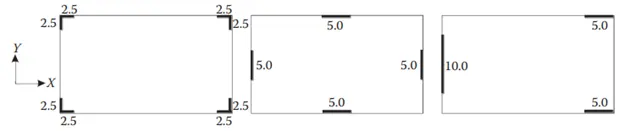
As the structure is more restrained it will be more shrinking, expanding and cracking. There will be more floor shrinkage and expanding in structure A whereas there will be minimum cracks in structure B and C The shear walls in the structure also decide whether the floor vibration is more or less in the structure it will be better placing a column at the corners So that it will reduce the cracks instead of having a shear walls at the corner in the structure. The Torsion in the structure C is more when compared to structure A and B because in the structure C there will be an eccentricity. The redundancy in structure A and B is more when compared to structure C because there will be an eccentricity in structure C in the left side where the length of the wall 10 meters which cannot carry load equally in either direction. For Lateral stiffness structure is more laterally stiff when compared to the structure A and structure B because there will be an eccentricity in structure Cin the left side where the length of the wall 10 meters which cannot carry load equally in either direction.
Question 2:-
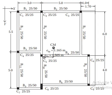
in this figure, the frames are not continous and symmetric and one of the column is not unifrom. and because of irregularity of frames from earthquake point of view it not safe due to lack of redundancy and siddha it will suffer from load multiplicity, fewer plastic hinges and less cost effective use of concrete. if there is termination at the beam column joint,then there will be no uniform transfer of internal stresses. and in this layout,only the top frame beam is continous, and in the bottom two frames there is column at the joint,i.e there is termination at one end,and then after termination a new beam is laid. these kind of arrangements make a lot of problems on the site, hence they should not be preferred and we can see in the beam B7 only one end is supported by column, where as the other is left to be supported by beam, this kind of arrangement is not permissible because it may lead to soft storey. in this plan column 8 and beam 6 centres should coincide with each other, if they do not coincide it will lead to torsion. and the maximum permossible eccentricitylis given by b/4, and it should not be more than that according to code provisions. siddharth In there is chance of torsional flexibility in the building as we can see that there is a room in the plan which is extending outside the plan, and if the lateral force acts on this area there will be rotation insome parts of the building. a fundamental translational mode of vibration is larger than fundamental rotational mode of vibration counselling ses because translational mode is due to the irregularity or discontinuity of frames from earthquake point of view it not safe due to lack of redundansy and it will suffer from load multiplicity, fewer plastic hinges and less cost effective use of concrete. since there are two frames which are irregular where as if we see the rotation or torsion is only due to the torsional flexibility in the building as we can see that there is a room in the plan which is extending outside the plan, and if the lateral force acts on this area there will be rotation insome parts of the building, as there is only one source of damage due to rotation and two for translational in the form of frames, hence translational mode of vibration will be higher.
Question 3:-
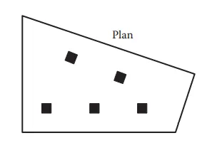
As per the plan dimensions, we can understand that the center of mass will situate on the left side portion of the floor plan, as the area of floor is larger on the left side. So we have to position the lateral load resisting system in such a way their stiffness center should come near to the center of mass. This is mandatory to avoid torsional irregularity.
The suitable Lateral load resisting system: Since the floor plan is an irregular quadrilateral, the influence of X-direction earthquake will also have effect in Y-direction, and vice versa. So a lateral load resisting system which should have bi-directional strength to resist seismic forces. So we can suggest L-shaped corner RC wall arrangement.
For this L-shaped RC wall irregular corner arrangement, we can go with two possible foundation options. One is, isolated footings with tie beam connection. The other is, whole box type foundation.