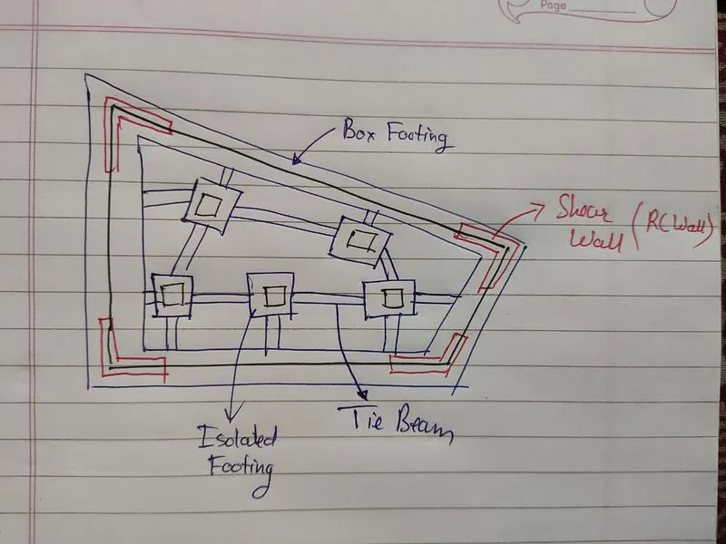
Conceptual design of a building with columns and shear walls
Question 1:
The building shown, 20 × 35 m in plan, has columns on a 5 × 5 m grid and shear walls (with dimensions shown in m, 250 mm in thickness) in three alternative arrangements, (a), (b), (c), all with the same total cross-sectional area of the shear walls. Compare the three alternatives, taking into account the restraint of floor shrinkage, the lateral stiffness and the torsional one with respect to the vertical axis, the vertical reinforcement required for the same total flexural capacity at the base, the static eccentricity, the system’s redundancy, foundation systems, architectural constraints etc.
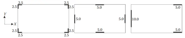
(a) (b) (c)
Restraint of Floor Shrinkage:
(a) All 4 corners are restrained against shrinkage so there is the possibility of more cracks.
(b) Edges of the building are restrained and corners are left free so there is less possibility of generating cracks compare to option (a).
(c) Option (c) is unevenly restrained for shrinkage so it may generate very less cracks.
Lateral Stiffness:
(a) Corner Shear wall will provide good Lateral Stiffness in both X & Y directions.
(b) Edge shear wall will provide more lateral stiffness compared to option (a) in both X & Y directions.
(c) Option (c) has an unevenly placed Shear wall that will provide poor lateral stiffness compared to (a) & (b).
Torsional Stiffness:
(a) Corner wall will offer the best torsional stiffness compared to (c) and (b).
(b) Shear walls at the edges of the building offer good torsional stiffness.
(c) Option (c) offers the worst torsional stiffness because of uneven placements of the shear wall.
Vertical reinforcement required & Total Flexural Capacity:
(a) Corner Walls are subjected to normal moments and heavy twisting so the steel required is more than option (b).
(b) Edge walls are subjected to normal moments and normal twisting so the steel requirement is normal.
(c) Uneven walls are subjected to heavy moments and heavy twisting so the steel requirement is high.
Static Eccentricity:
(a) Structure (a) and (b) are symmetric so there will be no static eccentricity.
(b) Structure (c) is unsymmetric so have static eccentricity.
Systems Redundancy:
(a) Structure (a) and (b) are more redundant because of the Uniform placement of the lateral load in both directions.
(b) Concentrated load support in both directions so less redundant.
Foundation Systems:
(a) Because of L-shaped Walls the design and detailing of the foundation will be difficult and can provide isolated footing or box foundation.
(b) Easy to design and can provide isolated footing or box foundation.
(c) Critical to design can provide peripheral box foundation.
Architectural Constraints:
(a) Only corners of the building are obstructed, most preferable.
(b) Face of the building is obstructed because of the wall at the center.
(c) Passage is been blocked by a vertical wall, least preferable.
Question 2:
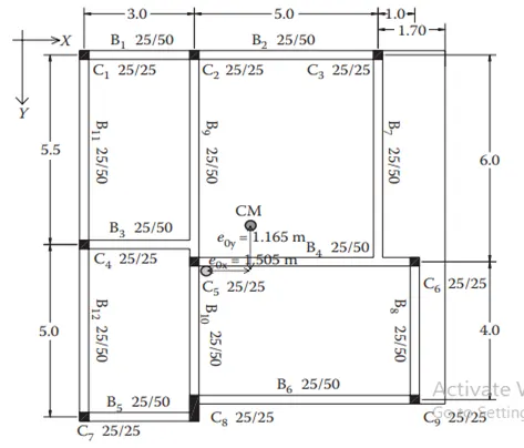
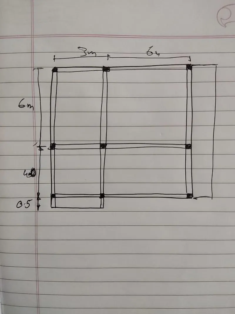
Discuss the suitability for earthquake resistance of the moment resisting framing plan of a three-storey building depicted here (cross-sectional dimensions in cm), the eccentricity of the centre of mass (as centroid of floor plan) to the centre of stiffness (from the moments of inertia of the columns) are shown. Suggest an alternative. Also, is there torsional flexibility? Are the two fundamental translational modes of vibration larger than the fundamental torsional mode of vibration. Discuss qualitatively.
Question 3:
A multi-storey building with basement, with a quadrilateral (non symmetrical floor plan) plan as, has interior columns in an irregular (not in a grid) pattern in plan that serves architectural and functional considerations. Partition walls and interior beams supporting the slab have different layout in different stories. However, there is no constraint to the type, location and size of the lateral force resisting components and sub-systems on the perimeter. Proposals are to be made and justified for the choice of the lateral-load-resisting system and its foundation.
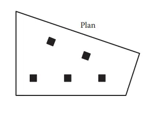
The plan of the building is irregular in shape and the orientation of column is not in the X and Y directions. So the special torsion load resisting moment frame should be accommodated.