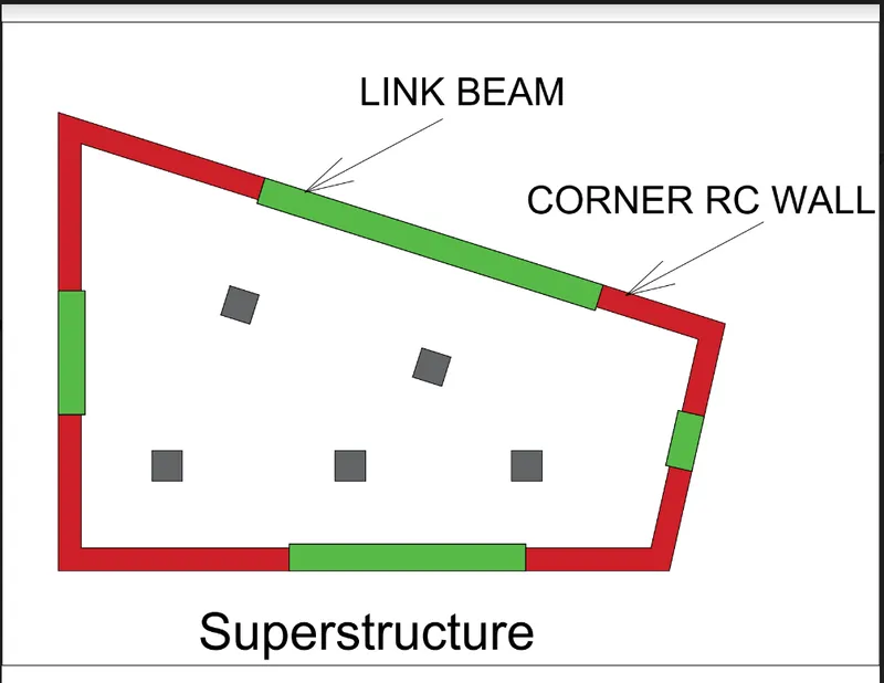
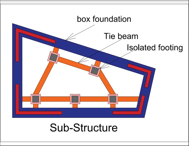
Conceptual design of a building with columns and shear walls
Q1)
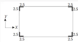
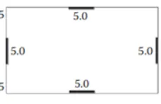
Three different arrangement of shear walls are provided with equal plan cross sectional area of four shear walls and each having a length of 5m. Analysing the system with different arrangement of shear walls ar periphery and finding out the effects in restraint of floor shrinkage, the lateral stiffness and the torsional one with respect to the vertical axis, the vertical reinforcement required for the same total flexural capacity at the base, the static eccentricity, the system’s redundancy, foundation systems, architectural constraints
Case 1
Restrained of floor shrinkage
Shear walls are provided at each corner symmetrically. Since it is placed symmetrically at all corners the structural system is highly restrained to floor shrinkage with variation of temperature or any other shrinking charecters. No shrinkage will occur even Seismic forces will act along both the orthogonal directions. Since it is highly restrained Cracks can be formed at these places. Cracks are formed due to restains hemce they are not structural cracks.
Lateral Stiffness
Shear walls are placed at corners normally dont have the complete lateral stiffness compared to when it is placed at periphery in a symmetrical manner. So in plan it can be summerise that lateral stiffness is comparitively less in both orthogonal X and Y directions.
Torsional resistane
The corners of a floor system undergoes tosion more under loading. In the figure we can see that corners are restrained with shear walls are highly restrained. Hence torsional resistance will be more.
Vertical reinforcement for similar base capacity.
Wall are arranged symmetrically at corners hence eccentricity will be less and redundant. Hence nominal flexural moments are acting on it. But corners are subjected to heavy twisting moment hence more reinforcment are needed for resisting the twisting moments.
Static Eccentricity
Since the structural walls are placed symmetrically, no eccentricity generated.
Structural Redundancy
Structural walls are arranged uniformly, hence the load is shared in equal amounts in both the axes. Load can be transmitted uniformly without any load concentrations.
Foundation System
L shaped walls are present at corners which will cause flexural moments and high twisting moments. Becuase of this reasons and non regular shape (compared to rectangular, square) foundation system is critical and it may be uneconomical. Isolated or strip foundations may not be suitable in this case. We can privide isolated peripheral box foundations for this type of shear walls.
Architectural Constrains.
This arrangement is ideal for any buildings since it will not affect any aesthetic features of a building. No such things seldom see at the corners of a multistory buildings like windows doors etc. It consumes less space also (2.5m each side), hence this can be adopted for buildings.
Case 2
Restrained of floor shrinkage
Edges are restrained to a fair degree but edges are unrestrained
Shrinkage can be occur at corners. It can provide restrains to floor from seismic forces at both orthogonal directions. But over all average degree of restraining against shrinkage cracks due to temperature variations.
Lateral Stiffness
When shear walls are placed at edges symmetrically, the lateral stiffness will be higher than other arrangements. Hence the plan given have higher lateral stiffness in orthogonal X and Y direction than other two plan configurations under pure seismic forces.
Torsional resistane
Torsional resistance of this configuration is fairly good since it is placed symmetrically and no eccentricity generated with respect to X and Y directions. Less compared to configuration 1 since more twisting moment generated at corners and here corners are free .
Vertical reinforcement for similar base capacity.
Walls arranged symmetrically at edges hence flexural moments are less. Corners are not restrained against torsion hence torsional reinforcements are also less. Load paths are uniform since the structure Is redundant. vertical reinforcement needed is lesser among the three combinations.
Static Eccentricity
Since the structural walls are placed symmetrically, no eccentricity generated.
Structural Redundancy
Structural walls are arranged uniformly, hence the load is shared in equal amounts in both the axes. Load can be transmitted uniformly without any load concentrations. Hence we can say that the structural system is redundant.
Foundation System
Walls are arranged in a line and forces are acting is less. Foundation analysis and design procedure may be simple and economical. Construction process will also be simple. Simple isolated footings or strip foundations can be adopted for this structural wall system
Architectural Constrains.
Since walls consumes large area on each faces of the building the architect cannot provide features like windows, door, glazed partitions on those faces which are essential for a multi-storey building in architectural point of view. Hence the arrangement should be discussed with the architect before design processes.
Case 3
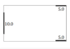
Restrained of floor shrinkage
Non uniform restrains at corners and edges.
Shear walls are provided unsymmetrically. Corners at left side and edge at right side are not restrained, hence shrinkage cracks will not be formed at those parts due to temperature variations and other reasons. Since the system is not restrained, chances of forming shrinkage cracks are less.
Lateral Stiffness
Arrangement of shear walls are unsymmetrical and non-uniform. Hence the behavior of lateral stiffness under seismic action in uneven or non-uniform.
Torsional resistane.
Torsional resistance is very poor in this case since non-symmetrical arrangement of shear walls induces large eccentricity and hence larger is the twisting moment.
Vertical reinforcement for similar base capacity.
Walls are arranged non-uniformly and high eccentricity is generated hence the system is subjected to high flexural moments. Due to high eccentricity and low redundancy torsion generated will also higher and hence large vertical reinforcements are needed.
Static Eccentricity
Structural walls are placed with significant amount of eccentricity. This will cause complex designing process and consumes more amount of reinforcements and hence it becomes uneconomical. Eccentricity in this configuration is highly significant and cannot not be ignored.
Structural Redundancy
Since the walls are placed non-uniformly, load path will not be uniform and lot of load concentrations occurs in each axes. Hence we can say that the structural system is not redundant.
Foundation System
Foundations are arranged in a line hence fixing the geometry and Construction process will also be simple. Simple isolated footings or strip foundations can be adopted for this structural wall system. Since large amount of flexural and twisting moments are generated, analysis and design procedure may be critical and complex. Because of this reason foundation for these walls may be uneconomical.
Architectural Constrains.
Wall on left side consumes almost all the face of the building making it unusable for any kand of access, passages or any kind of opening. Hence this configuration cannot be used in any high rise buildings unless insisting by the authority in charge.
Q2)
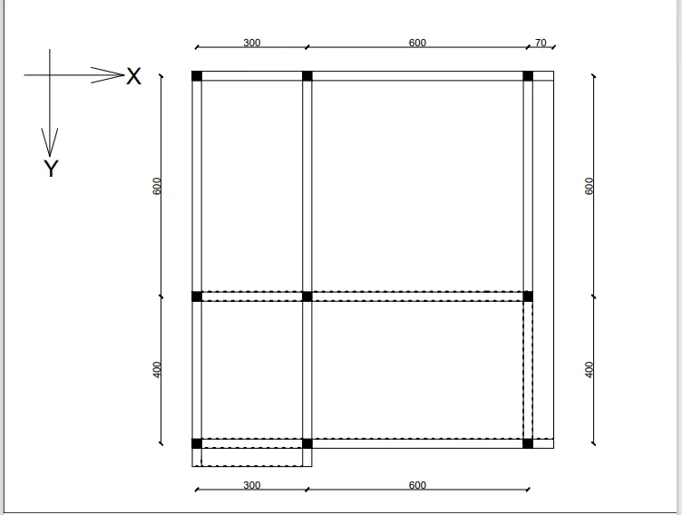
There are some issues with placing of beams in the framing plan which is marked and shown below
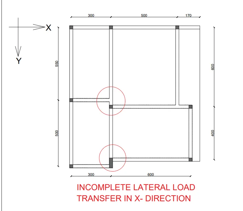
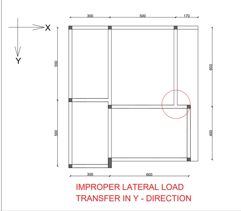
Beams are not connected to the columns directly as in the above sketch. Under static condition it may not create a big problem, but under lateral loading large shear forces induced on primary beams from the secondary beams which will leads to the shear failure of primary beams. primary beams drawn under circle will fail due to this reason. Incomplete lateral load transmission in X and Y directions are shown in above picture.
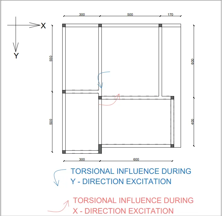
Center of mass and center of rigidity did not coincides or eccentricity developed
If Center of mass and center of rigidity did not coincides at a point eccentricity developed and induces twisting moments. In the plan it can be seen that CG and CR are eccentric both in X and Y axes and induces large twisting moments. In the plan the eccentricity in both direction measures more than 1 m which means larger value of twisting momemts generated under seismic loading.
Possibility of Weak column strong beam philosophy
From the plan it is clear that area moment of inertia of beam(25 cm x 50 cm) is higher than columns (25 cm x 25 cm). Clearly sectional sizes are bigger for beams. If the reinforcement provided not sufficient enough to carry the loaded beams, weak column strong beam condition occurs and under large seismic loading the columns will collapse first and which should not be allowed. This cannot conclude with the plan view alone . We need reinforcemnt details for final conclusion. But it recommended to provide column sections larger than beam sections.
Alternate Frame arrangement is shown below.
As far as possible connect beams directly on columns. Try to avoid placind secondary beams. Avoid the situation where beams are comnnected to the columns eccentrically (Bottom portion of the given plan) and place the columns in a line and connected them with beams concentrically. Eccentric distance can be managed with cantilever beams which are commony adopted in all RC buildings which is safer than beams are connencted eccentrically on columns. Slabs are also resting on cantiliver beams which is also a good way of placing of RC slabs
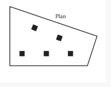
Q3) Plan provided in the problem as shown below
OBSERVATIONS
a) Floor plan
We can see that the floor plan is not symmetrical with respect to both the orthogonal directions. Hence surely under lateral loads large amount of twisting moments are generated. This system is very much uncertain in bidirectional stiffness mechanisms. Hence we need special lateral load resisting system to carted this large twisting and bending moments generated during seismic action.
b) Random arrangement of internal columns
As we can see the columns are arranged in random manner with respect to spacing and orientation. So it is clear that we cannot trust these columns are going to act efficiently against lateral loads. Also beam layouts are changing along the stories upward. Hence they unable to transfer lateral loads efficiently and effectively. Hence the columns and beams should only designed for gravity load cases not the lateral load cases. Special laterla load resisiting systems should be provided for this. Non linear dynamis analysis should also be done.
c) Partition walls and beam arrangements are changing with floor to floor
Partition walls are controlling the mass distribution of a building to a large extend. If it is uneven we need to consided and refer the codes for non uniform mass irregularities. Beams are also playing important roles in shear load transfer mechanism and act as a bridge between columns and slabs for the load transfer. These two important elements are arranged non-unifomly along the height in each floor this will cause high variations and distortions in lateral load carrying mechanism
SUGGESTIONS ON LATERAL LOAD RESISITING SYSTEM AND FOUNDATIONS.
- Heavey trosional forces will develop on the corners of the building, which can be resisted by corner lateral resisting systems like corner shear walls. Dimensions of the corner shear walls at left side will be more than that of right side since CG of the system is concentrated towards lest due to building is in the form of irregular Quadrilateral.
- Since the shape is irregular, it is difficult to place isolated or strip footings under the wall. So it preferable to use box foundation under the walls and also must provide tie (connection beams for efficient and proper load transfer. Internal columns can be supported over isolated or combined footings but they must be connected to shear walls using tie beams.
- Shear walls themselves connected with link beams inorder to transfer the base shear force in each floor level.
Above suggestions are shown in the picture below