2D CFD analysis of methane air combustion in a constant volume combustion chamber.
Aim –
- Volumetric combustion simulation in a 2D combustor model using Ansys Fluent.
- Studying the impact of water addition in the fuel inlet on pollutants (NO and Soot).
Introduction –
In this work, a combustion simulation has been performed on a 2D combustor model using Ansys Fluent. Steady state temperature, mass fractions of species and pollutants has then been calculated.
As an extension, the impact of water addition along with the fuel on NO, soot and other species has also been studied.
Modelling and Solving approach –
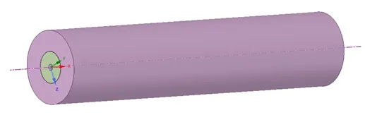
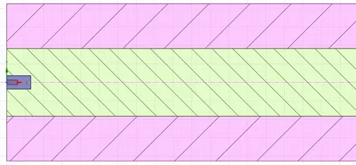
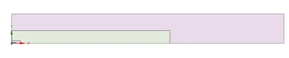
Solid Model – A 3D model of the combustor was provided. Modelling the complete combustor in 3D is computationally expensive. Thus, a 2D surface has been obtained from the 3D model. The model has been split along the xy and xz plane. The faces of the remaining geometry is then copied and pasted in a new design. After this, the share topology feature of Spaceclaim is then used to share all the edges of the geometry. This design is then saved and is used for analysis.
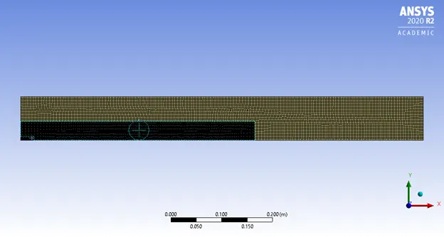
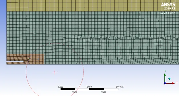
Meshing – Quadrilateral mesh has been utilized to mesh the 2D geometry using different face sizing in different regions to accurately capture the combustion phenomenon near the inlet.. Named selections are also created.
|
Method |
Tetrahedral |
|
Global Element size |
1 mm |
|
Capture curvature |
Yes |
|
Capture Proximity |
Yes (2 cells) |
|
Face Sizing (closest to inlet) |
0.5 mm |
|
Face Sizing 1 (next from inlet) |
0.5 mm |
|
Face Sizing 2 (outermost region) |
1 mm |
|
Number of elements |
~104000 |
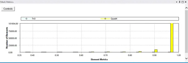
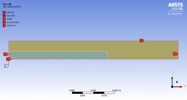
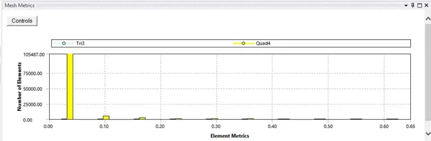
Solver Settings – Ansys Fluent was used as the solver and steady state simulations have been performed using a pressure based solver.
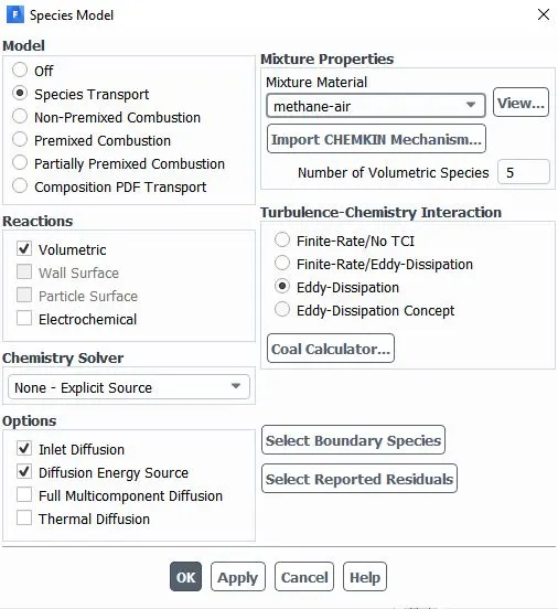
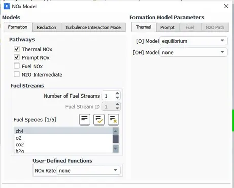
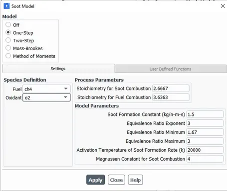
Computational model – Standard k – epsilon model with standard wall functions has been used for turbulence modelling. Species transport model is then used. Volumetric reactions have been considered with inlet diffusion and diffusion energy source consideration. Eddy dissipation TCI model has been used due to computational limitations. Methane-air is used as a mixture for Case 1 while methane-air (2 step) has been used for case 2. Thermal and Prompt NOx has also been modelled along with soot modelling (one step).
Boundary conditions and materials –
|
Named Selection |
Boundary condition - Momentum |
Boundary condition - Species |
|
Air Inlet |
Velocity inlet (0.5 m/s) |
O2 mass fraction = 0.23 |
|
Fuel Inlet |
Velocity inlet (80 m/s) |
Refer below table |
|
Outlet |
Pressure outlet (0 Pa gage) |
- |
|
Axis (always along x axis) |
Axisymmetric |
- |
|
Top wall |
Wall |
- |
Species boundary condition (mass fractions) for case 1 and case 2 –
As per the problem, water is added to the fuel and is varied from 5% to 30% by mole. The same has been converted to mass fraction at fuel inlet and is used. The below table gives the values of mass fractions of the species. The mass fraction of species not mentioned in the table has been assumed to be 0.
|
|
Case 1 (No water in fuel) |
Case 2 (Water in fuel) |
|
CH4 (Fuel Inlet) |
0.95 |
Varied from 0.944 to 0.675 |
|
O2 (Fuel Inlet) |
0.05 |
Varied from 0.056 to 0.325 |
|
O2 (Air Inlet) |
0.23 |
0.23 |
The mass fraction of CH4 and H20 has been considered as input parameter while average static temperature at outlet has been considered as output temperature for the parametric study. The parametric study method has been adopted for case 2.
Spatial Discretization – Coupled Pressure velocity coupling scheme was used to solve the Navier Stokes Equations. The default solution controls and methods have been used.
|
Gradient |
Least Squares Cell Based |
|
Pressure |
Second Order |
|
Momentum |
Second Order Upwind |
|
Turbulent kinetic energy |
First order upwind |
|
Turbulent dissipation rate |
First order upwind |
The solution has been initialized using the Hybrid Initialization method and has been run for 250 iterations for each design point.
Results and Discussion –
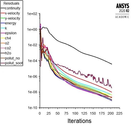
A known limitation of Ansys Fluent is that it gets stuck at updating solution stage in a parametric study if either any graphics window is open in fluent. To avoid this, none of the plots (residuals and average temperature at outlet) have been plotted in fluent.
After the study is complete, the residual plots can be extracted. To check if convergence has been reached the files of average outlet static temperature have been checked for convergence during the end of iterations.
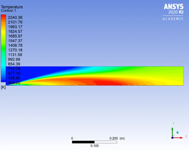
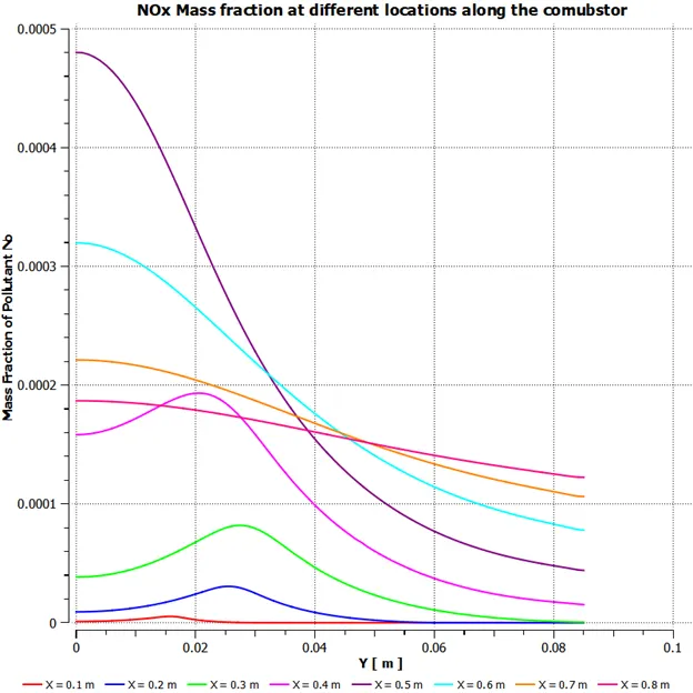
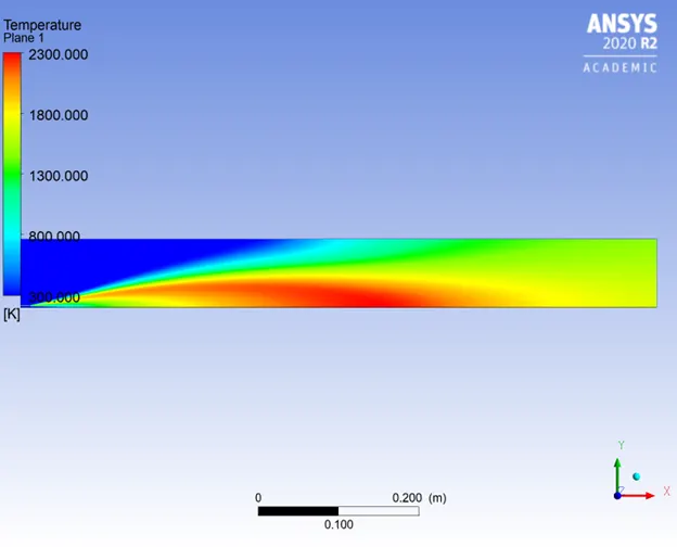
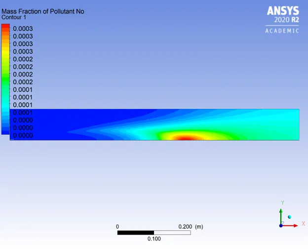
From the design point study it can be clearly observed that the average temperature at the outlet decreases with increase in mass fraction of water in fuel inlet. This lower temperature then results to lower NO production. This technique is now being adopted by major engine manufacturers in the industry.
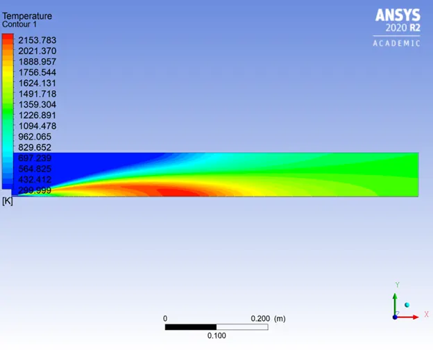
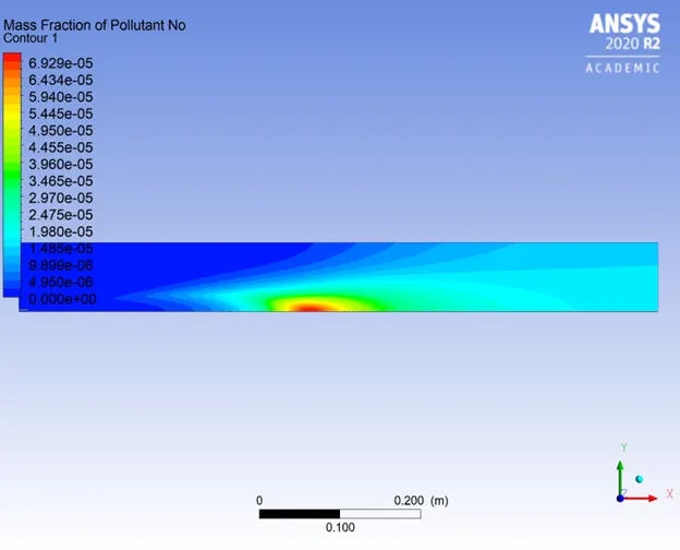
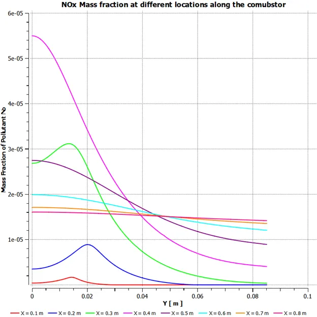
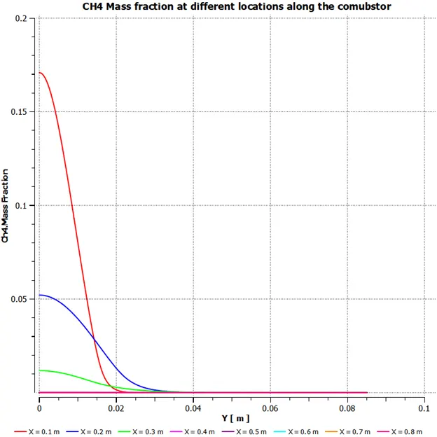
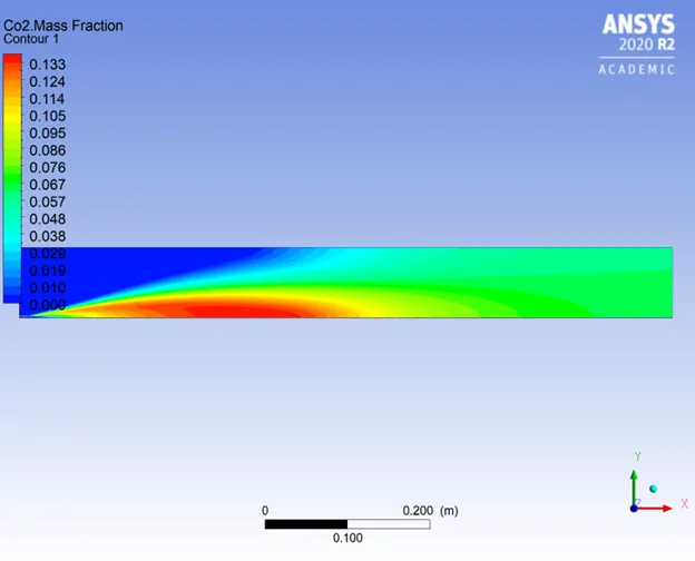
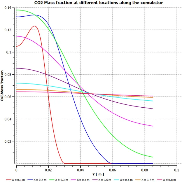
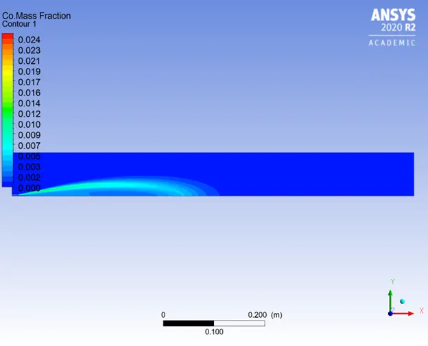
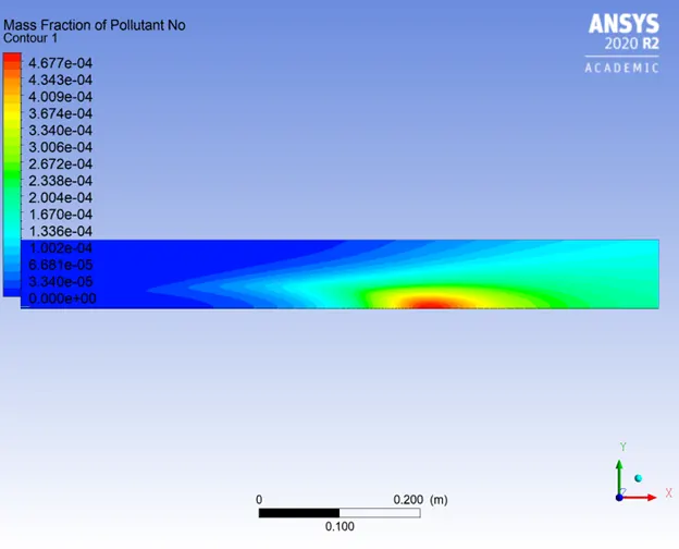
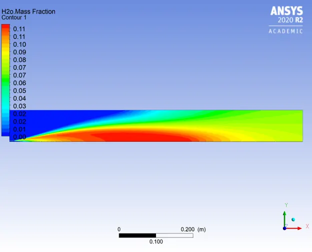
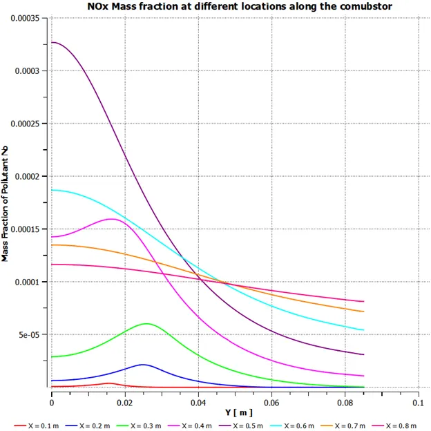
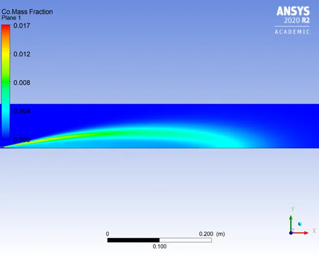
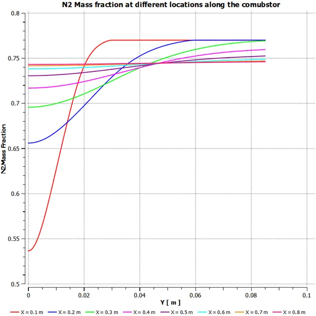
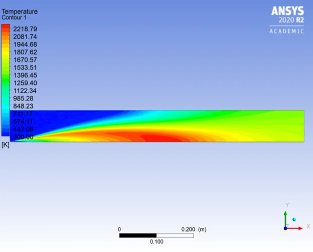
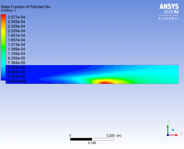
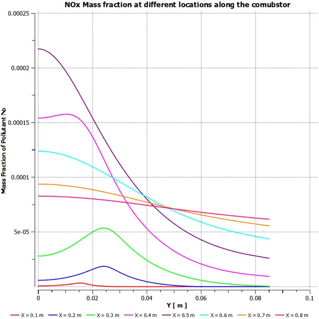
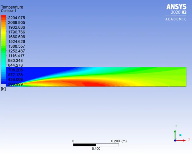
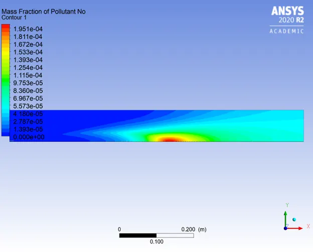
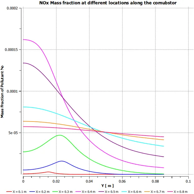
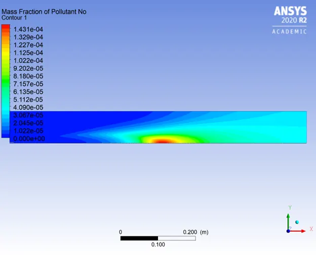
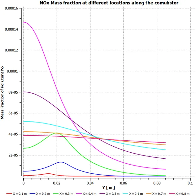
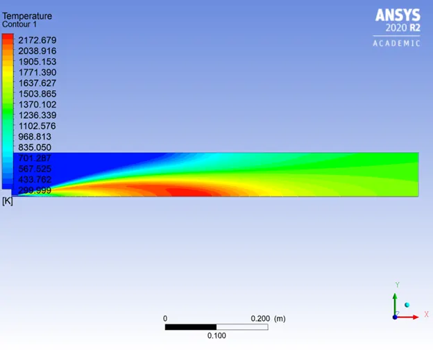
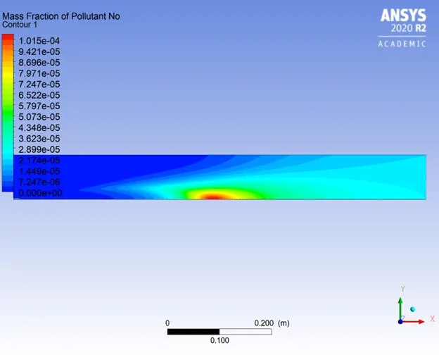
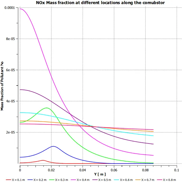
Upon comparing the temperature and NO mass fraction contours it can be concluded that NO formation takes place in the region of high temperature.
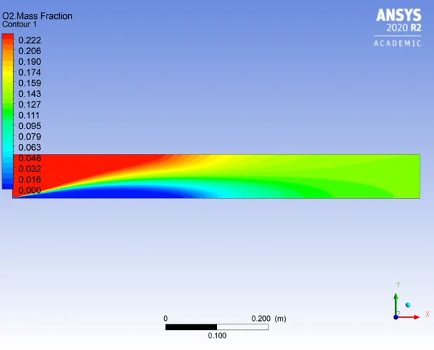
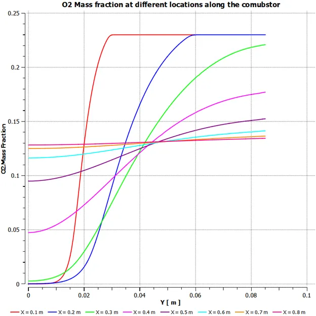
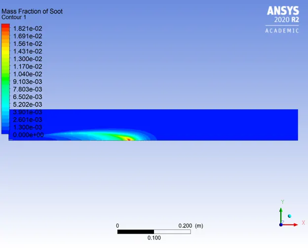
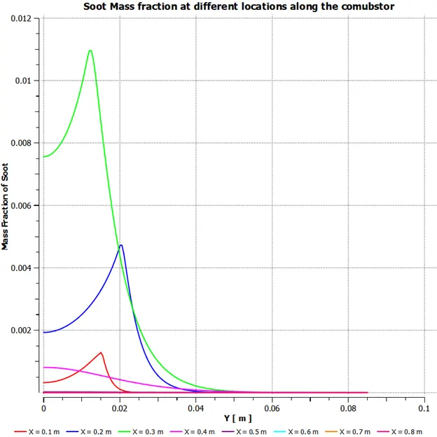
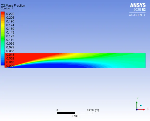
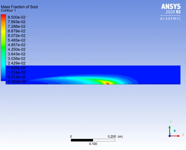
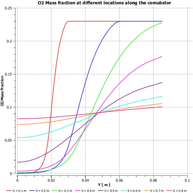
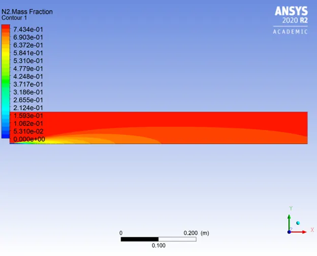
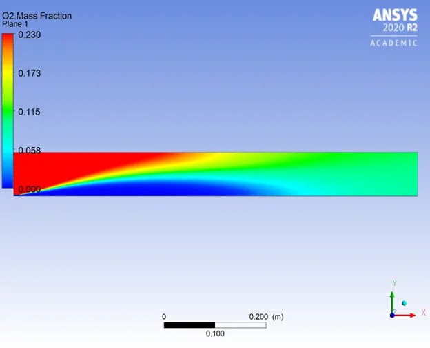
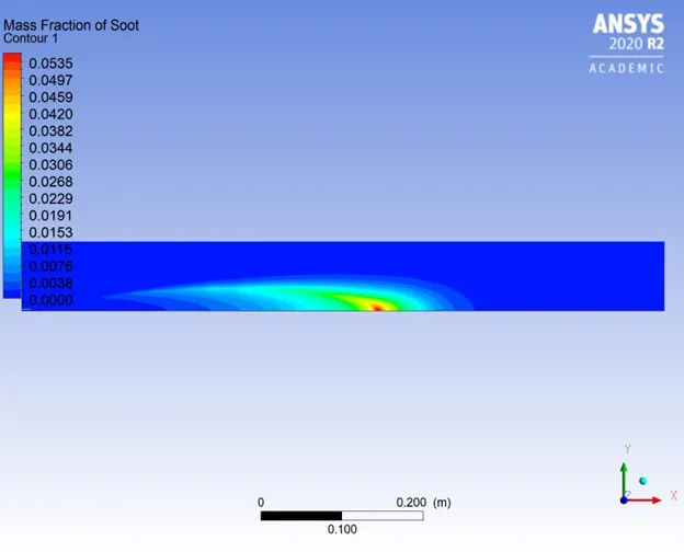
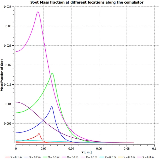
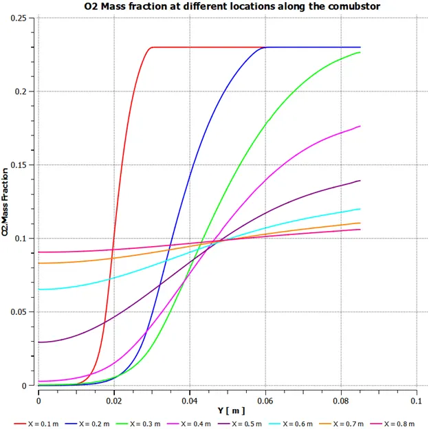
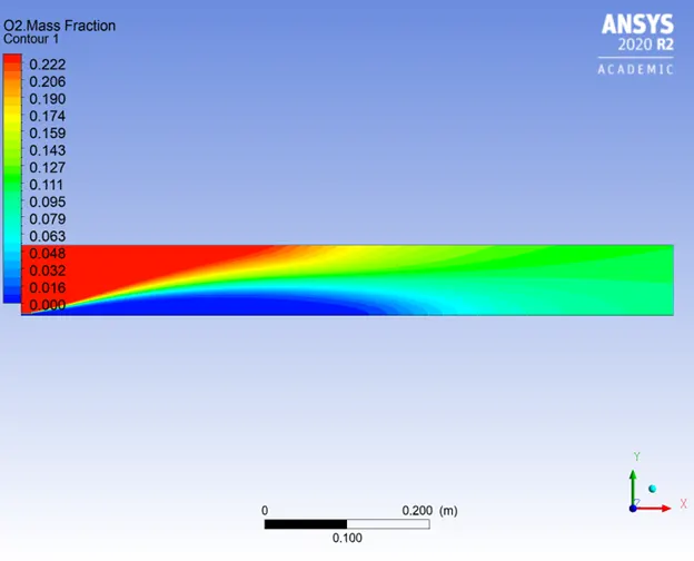
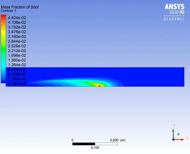
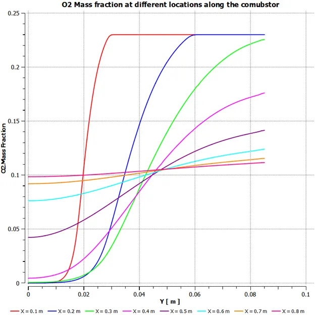
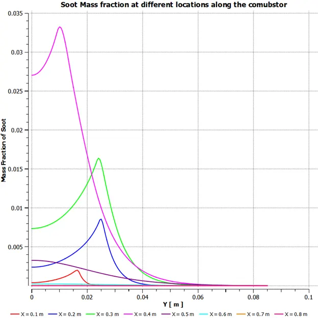
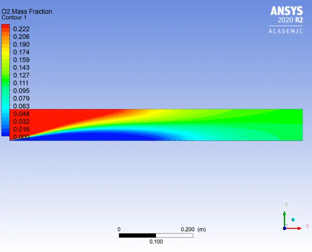
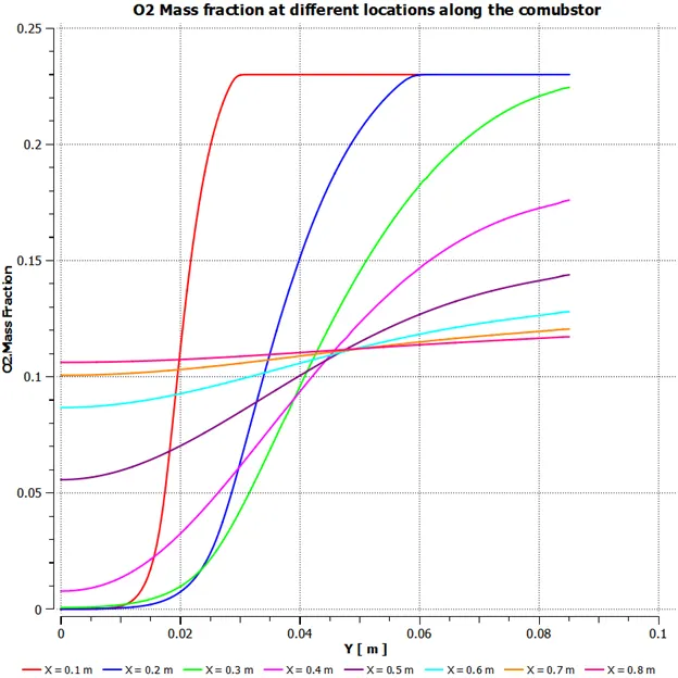
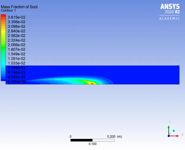
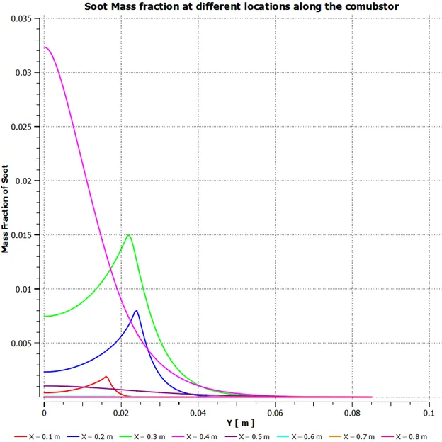
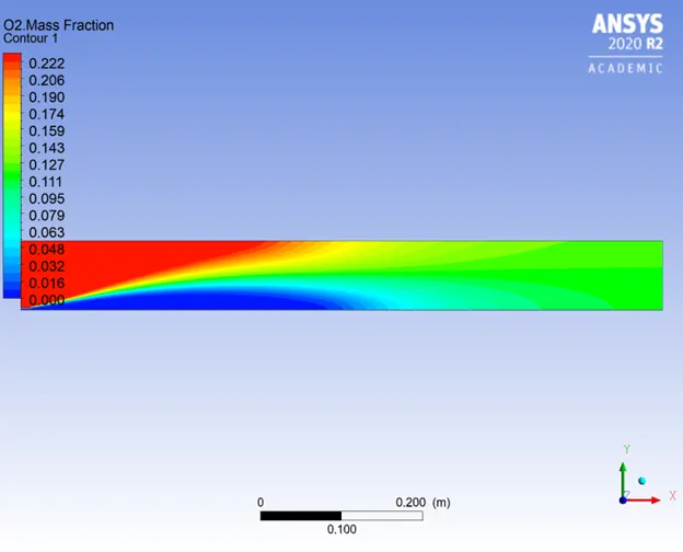
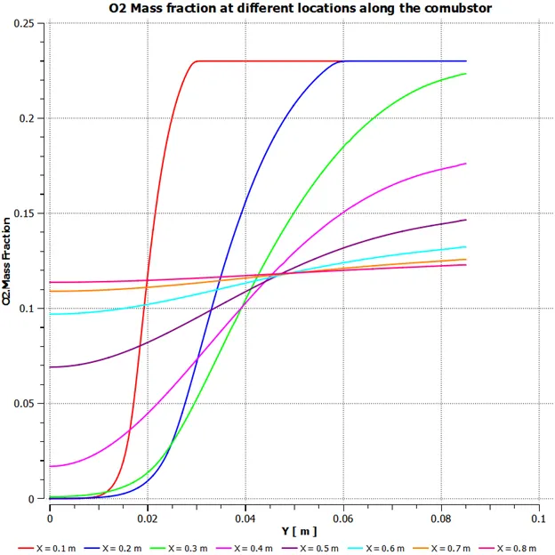
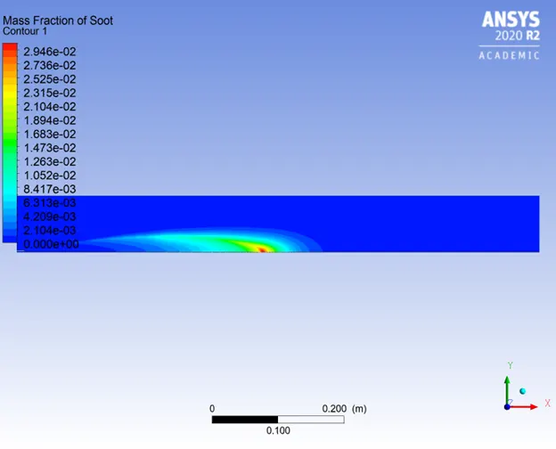
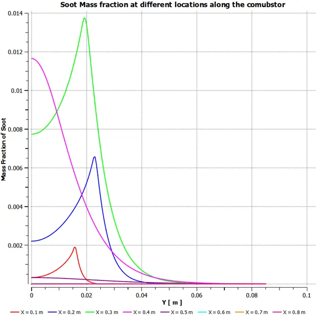
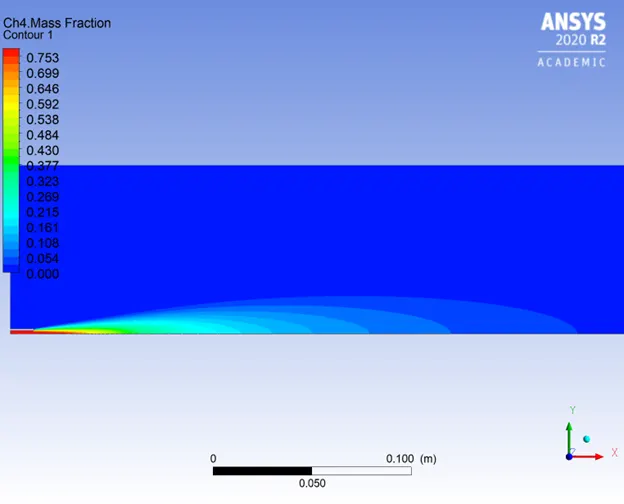
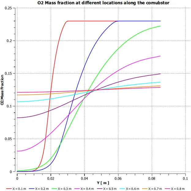
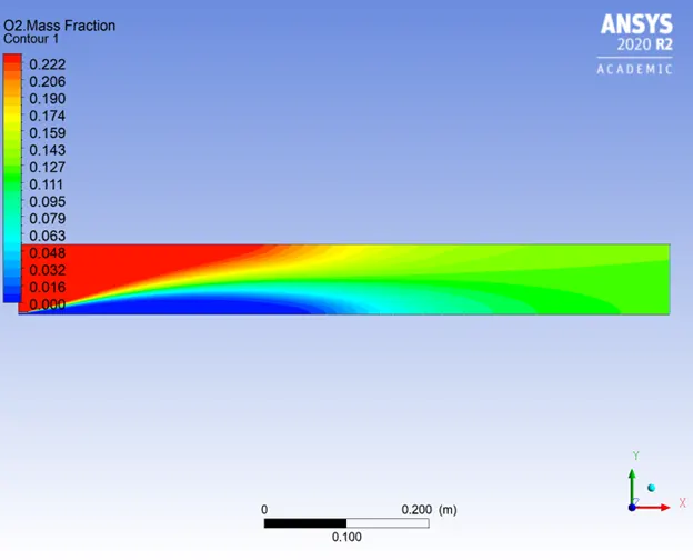
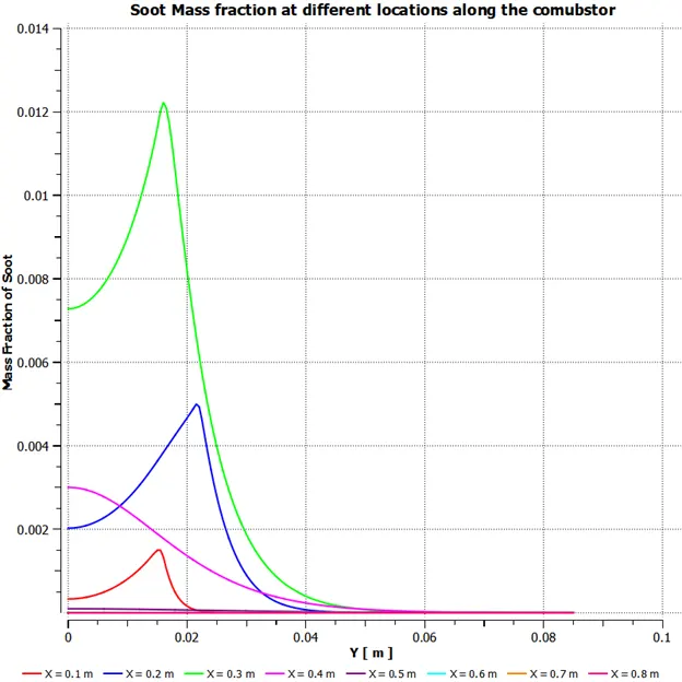
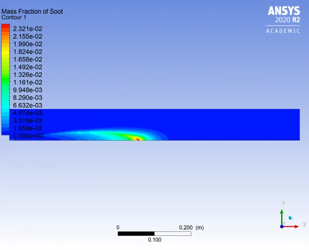
When contours of Oxygen mass fraction and soot mass fraction are compared, it is evident that soot formation takes place in the zone where oxygen is low and temperatures are high, thus the combustion is incomplete and soot is formed.
The below table highlights the important results of this study.
| Water mole fraction | Fuel Mole fraction | Water mass fraction | Fuel Mass fraction | Max NO mass fraction | Max Soot mass fraction | Max Temp (K) |
| 0 | 1 | 0.000 | 1.000 | 0.000484 | 0.088098 | 2309.68 |
| 0.05 | 0.95 | 0.056 | 0.944 | 0.000342 | 0.055443 | 2300 |
| 0.1 | 0.9 | 0.111 | 0.889 | 0.000270 | 0.045840 | 2287.33 |
| 0.15 | 0.85 | 0.166 | 0.834 | 0.000202 | 0.037453 | 2273.02 |
| 0.2 | 0.8 | 0.220 | 0.780 | 0.000148 | 0.030535 | 2257.16 |
| 0.25 | 0.75 | 0.273 | 0.727 | 0.000105 | 0.024053 | 2239.57 |
| 0.3 | 0.7 | 0.325 | 0.675 | 0.000072 | 0.018870 | 2219.99 |
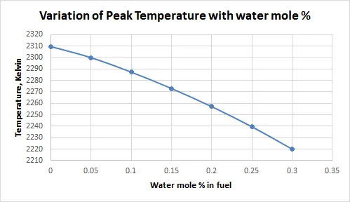
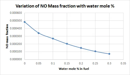
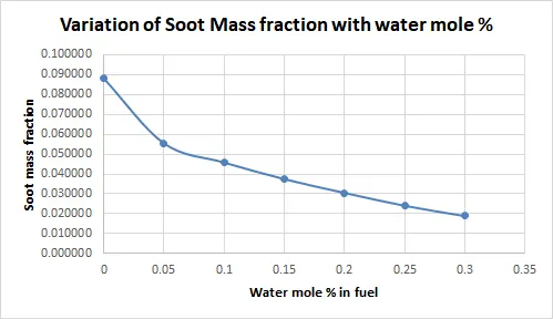
Below is the graphical representation of the above tabular data highlighting the impact of water addition in fuel.
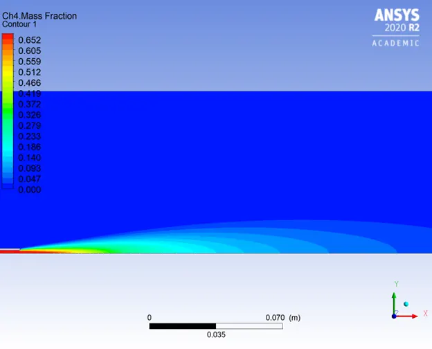
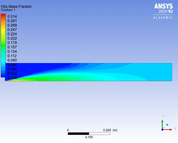
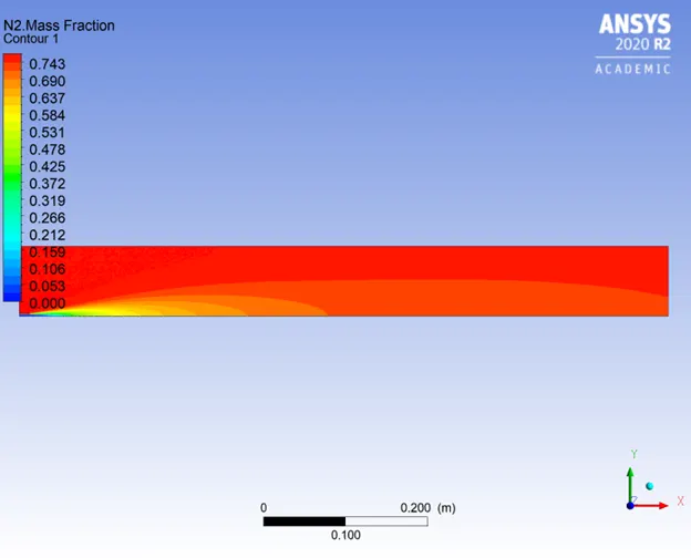
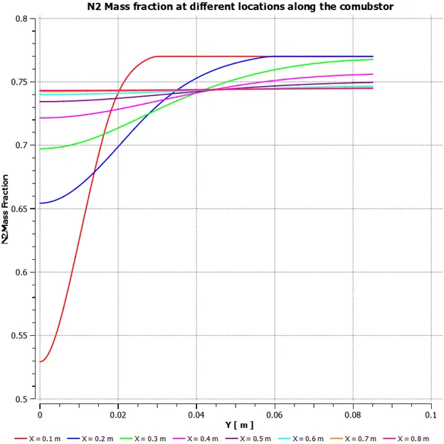
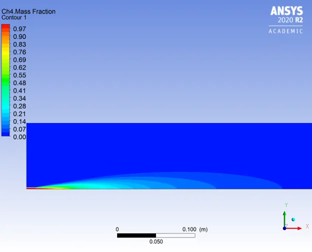
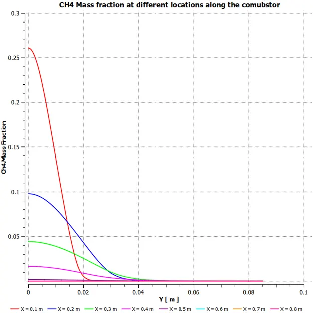
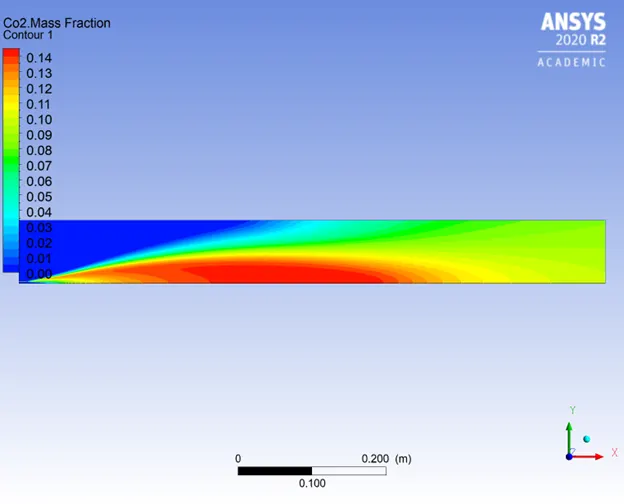
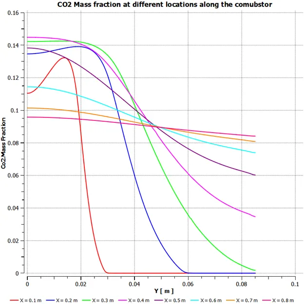
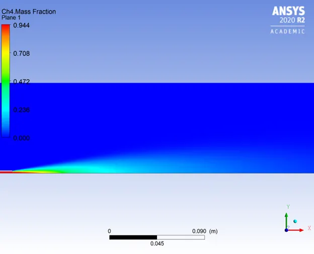
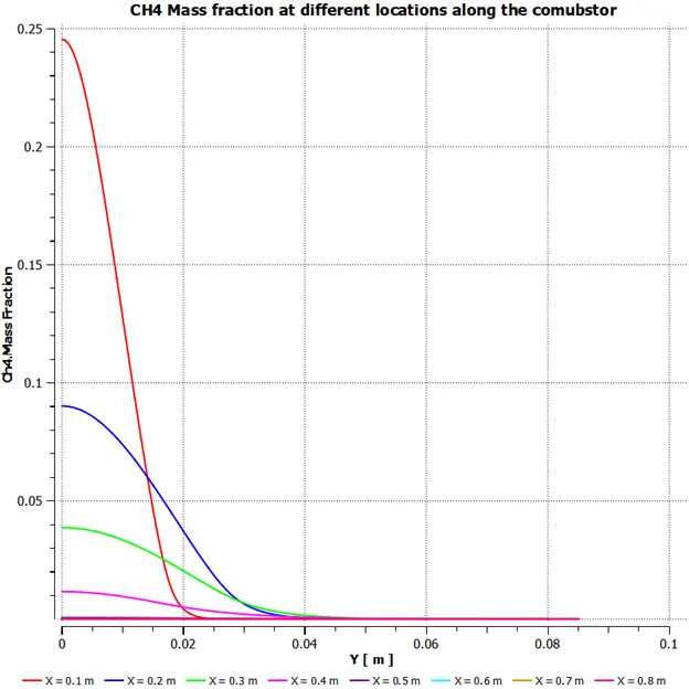
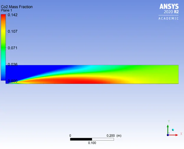
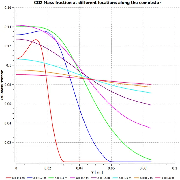
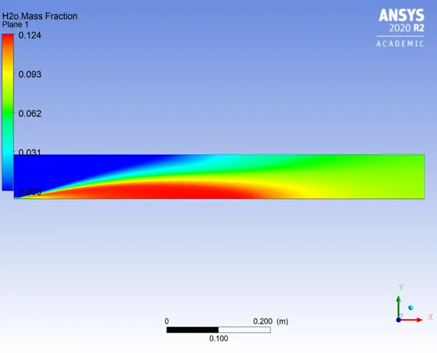
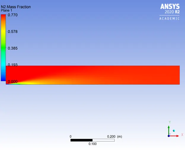
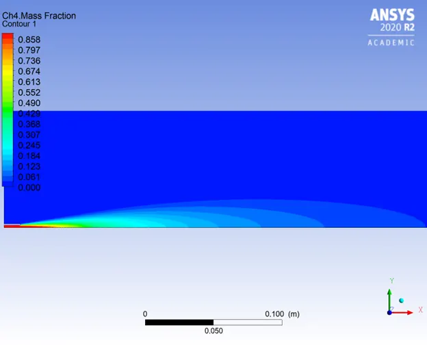
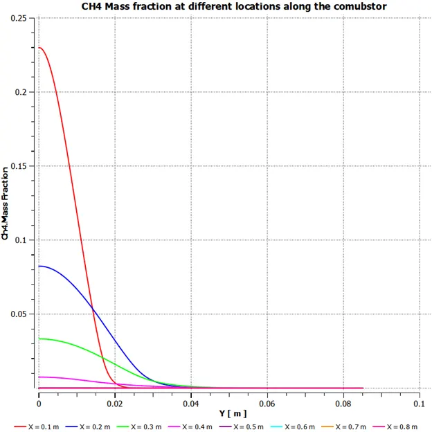
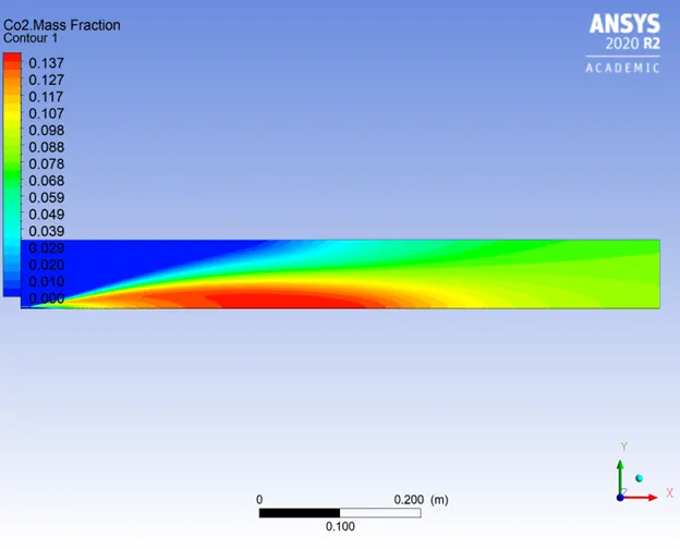
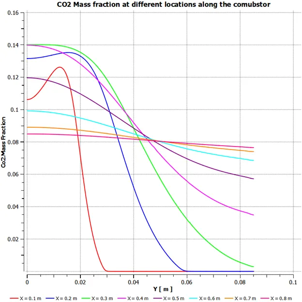
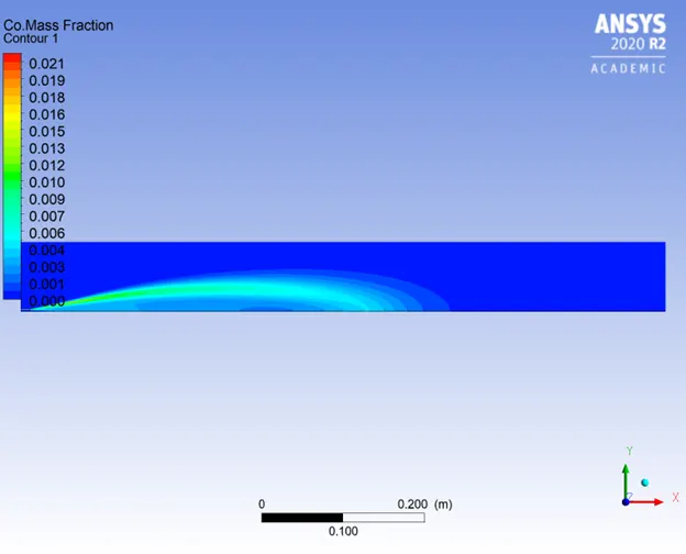
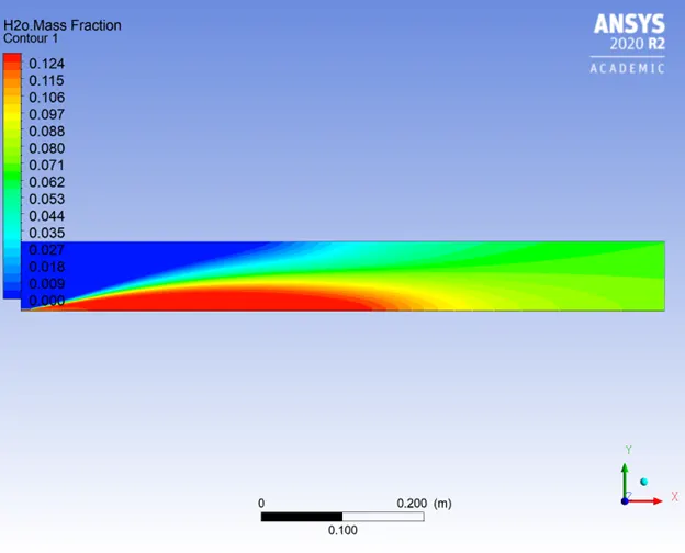
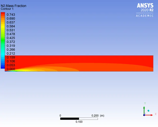
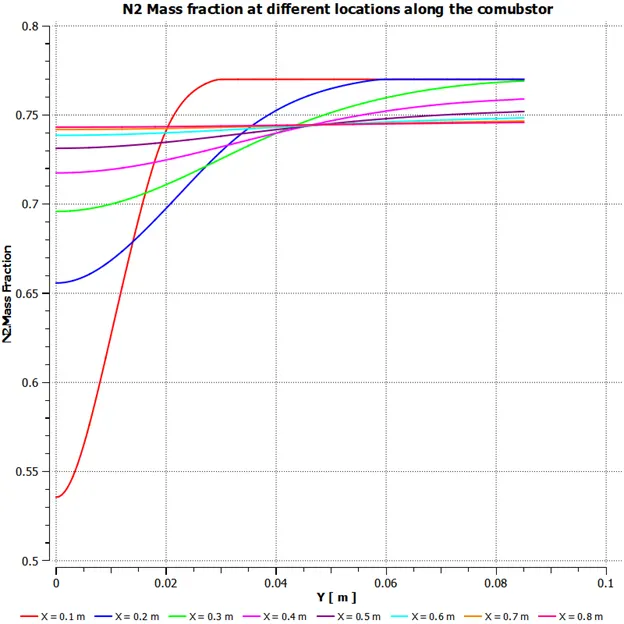
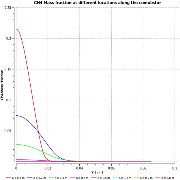
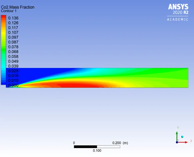
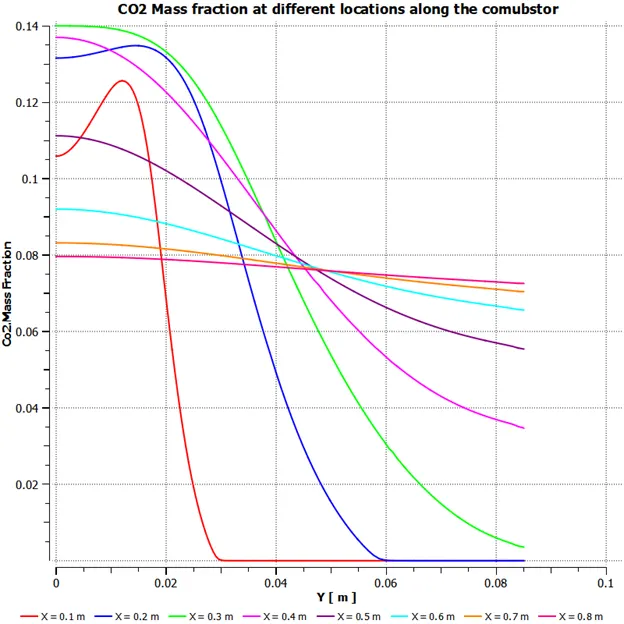
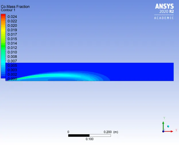
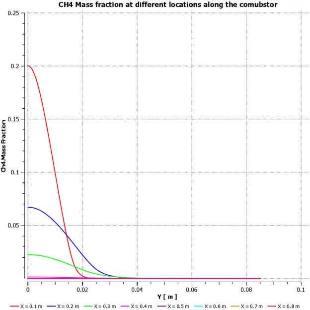
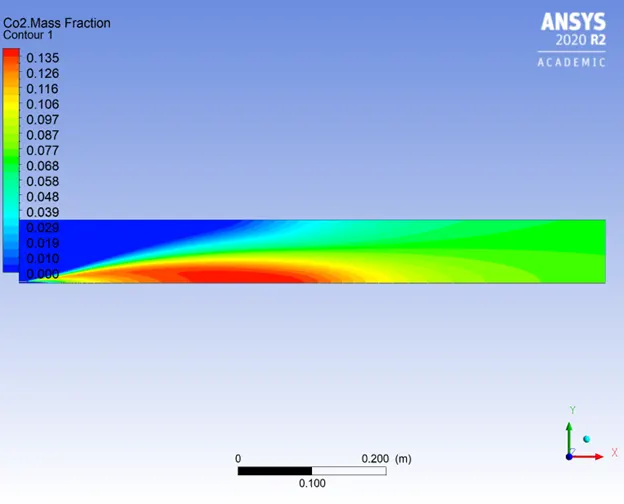
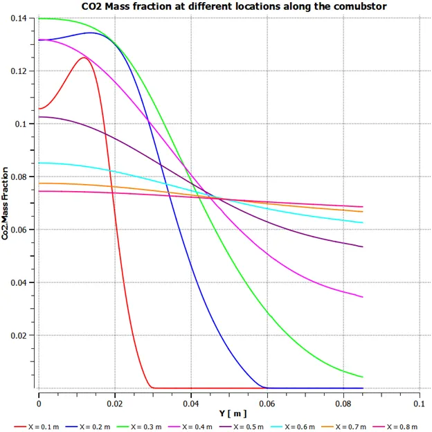
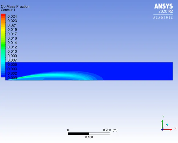
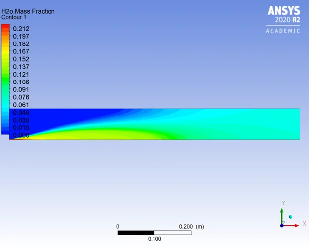
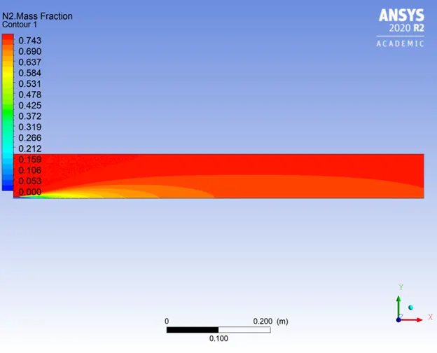
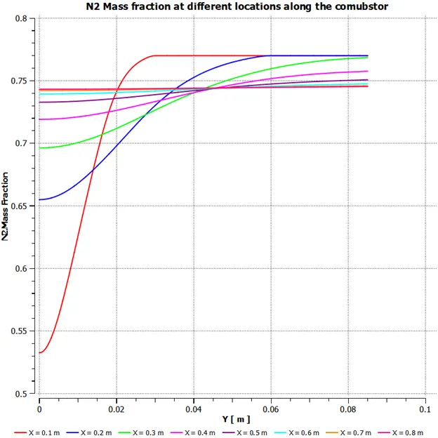
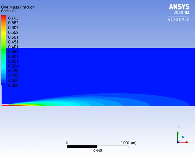
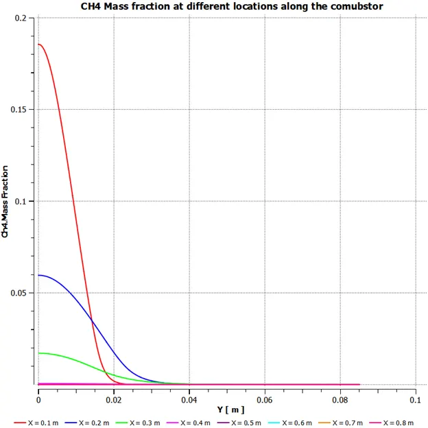
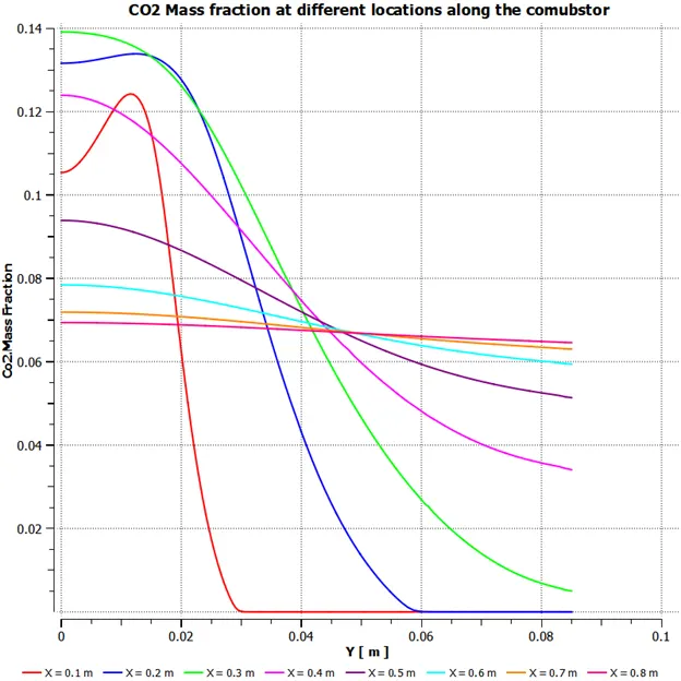
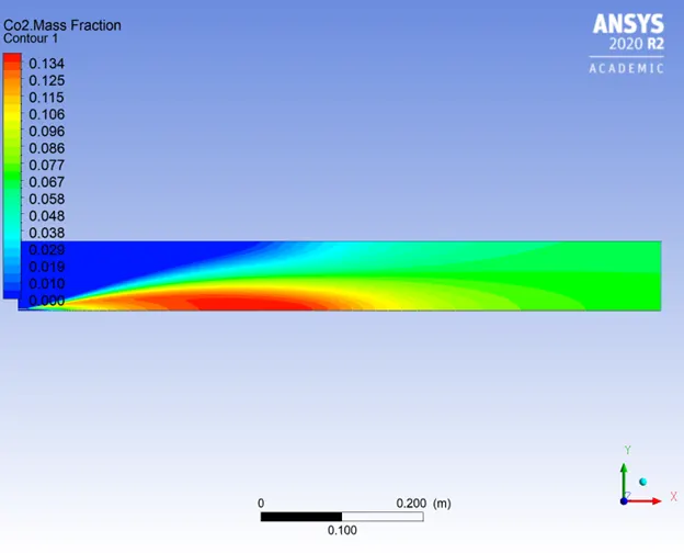
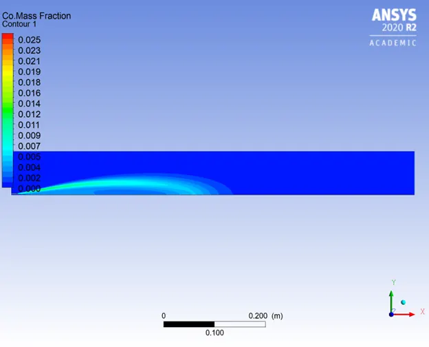
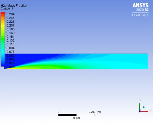
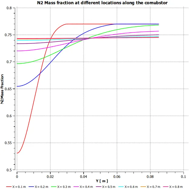
The relevant images of results of all the design points have been attached herewith.
Water – 0 %
Water 5 %
Water 10 %
Water 15 %
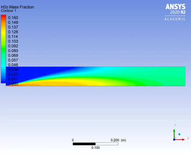
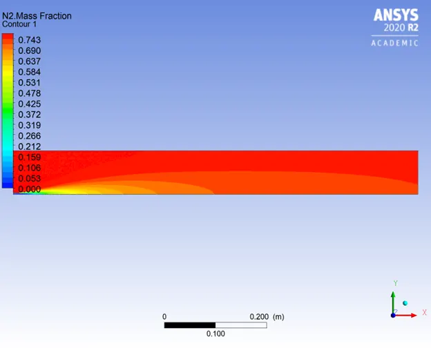
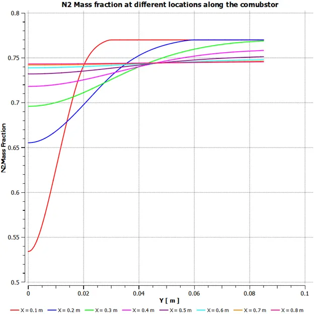
Water 20 %
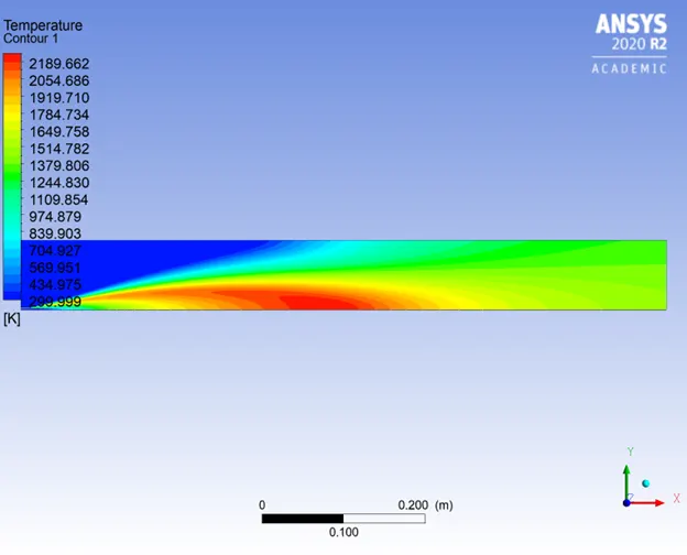
Water 25 %
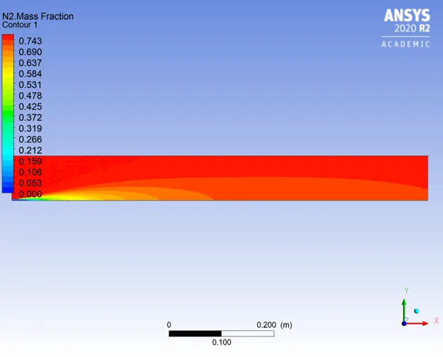
Water 30 %