Challenge on Combustion
COMBUSTION SIMULATION USING ANSYS FLUENT
AIM: To study the Combustion simulation of a non-premixed model using Ansys Fluent.
OBJECTIVE:
- To perform the combustion simulation on the combustor model and to plot the variation fraction of various species using different line probes at various locations of the combustor. (CO2, H20, CH4, N2, O2, NOx emissions and SOOT formation)
- By adding water content in the fuel from 5%-30%by mole, show the effect of the NOx and soot particles formed at the outlet of the combustor.
- Prove the study by plotting necessary plots and contours.
DESCRIPTION:
The combustion is defined as the chemoical process in which substances mix with oxygen in the air to produce heat & light. Combustion reactions happen at a very high temperatures.The methane reacts with oxygen to produce products of compounds of oxygen called oxides. Since methane is made up of atoms of carbon and hydrogen, the products of its combustion reaction are oxides of carbon and hydroge. Hence form carbon dioxide and water. The amount of a substance present in a sample is indicated by its mass or by the number of moles of the substance. A mole is defined as the mass of a substance equal to its molecular mass or molecular weight.
There are various of types of combustion simulations based on the mixing parameter i.e. Non-premixed Combustion, Pre-Mixed Combustion and Partially Pre-Mixed Combustion. In a Non-premixed Combustion, fuel and the oxidizer enter the reaction zone in various streams. Here the reactants are mixed at the molecular level before burning. For a premixed-combustion, they mix at the molecular level prior to the ignition. The combustion occurs as a flame front propagation into the unburnt reactants. Whereas for the partially premixed combustion, the fuel mixture is done during the compression stroke. Hence the premixied charge is too lean to ignite during the compression stroke, the charge will ignite after the last fuel injection ends near TDC. The partially premixed charge burns clean.
Here the combustion simulation on a combuster model is carried out using methane-air mixture by eddy dissipation model using Ansys Fluent. The rate of the reaction is bascially controlled by turbulent mixing, later part the mass fractions of different species are captured including Nox emissions and soot formation. As we know that soot particles and the NOx effects the environment, to reduce this we add water content in the fuel from 5%-30% by mole to the fuel and inspect the effects on the obtained results.
PROCEDURE:
Geometrey:
The geometry is imported to spaceClaim. Simulating the entire geometry considers more time as well as expensive and hence assuming that the flow is Axisymmetric. Here we have two important considerations i.e. fuel injector and air inlet. 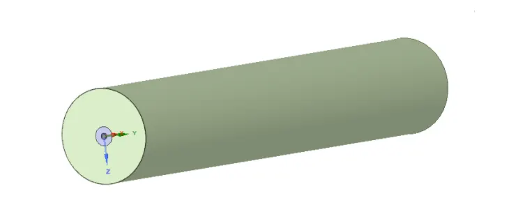
Now, the 3D geometry is converted to 2D and it is solved under Axisymmetric condition to save computational time. Here split the body into 1/4th of the entire geometry. On extracting the fluid volume we get the perfect 2D representation. Finally copy the final generated 2D representation to anaother window and delete the previous.
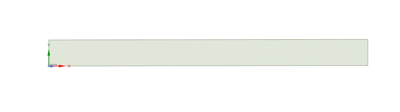
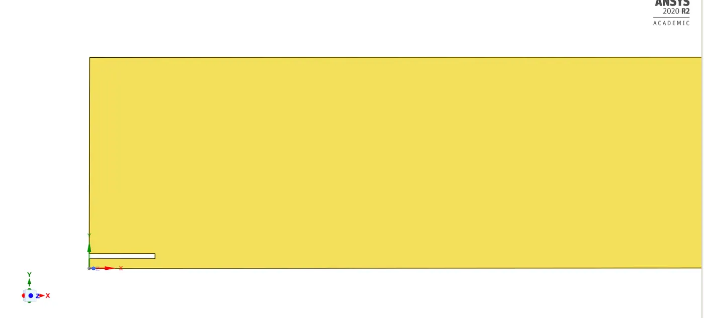
Meshing:
In this case for better results we need finer refinement of mesh. Hence element size is considered as 1.e-003m. Also select Capture proximity=ON.
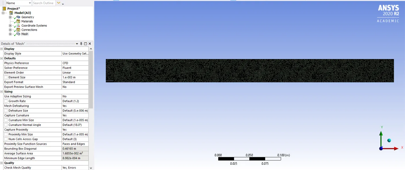
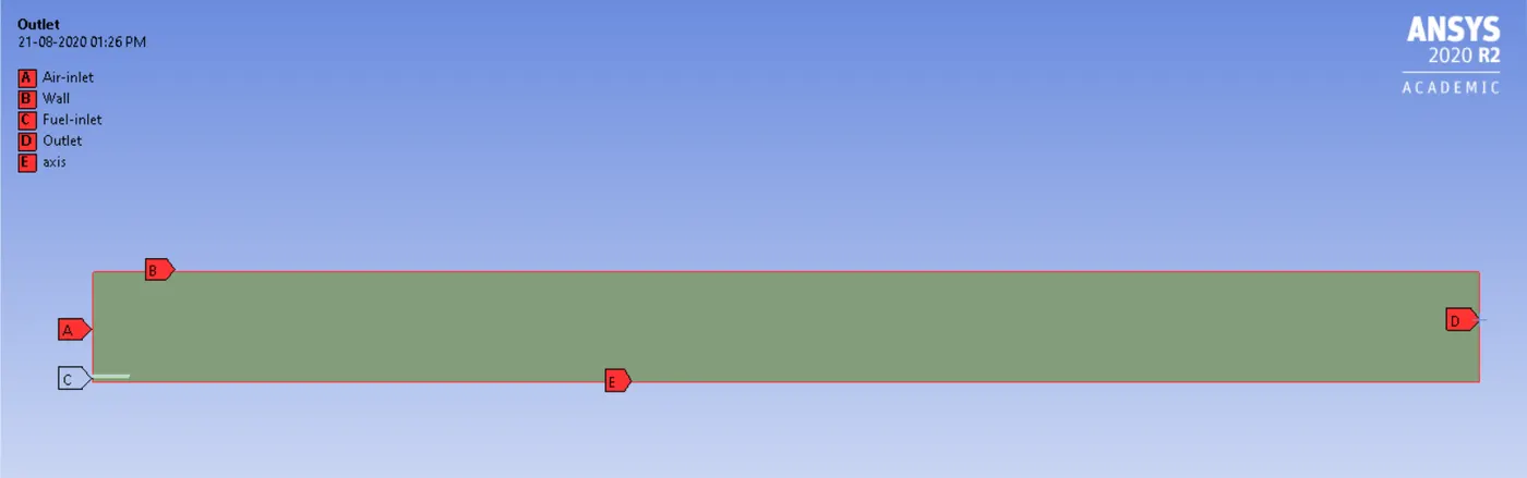
Named Selections:
Setting up Fluent:
- Go to Physics > Viscous model > K-epsilon - standard model - near wall treatment= standard wall functions.
- Select solver=Pressure-Based, Velocity Formulation=Absolute, 2Dspace=Axisymmetric, Time=Steady state.
- Go to Models > Species(species model) > select Model=Species Transport, Reactions=Volumetric, Options= select both Inlet Diffusion and Diffusion Energy Source, Turbulence Chemestry Interaction=Eddy-Dissipation. Also select Mixture Properties for part-1 is "methane-air" and for part-2 "methane-air 2-step" > Apply.
- In Material Selection
> for fuel without water select- 'methane-air'.
> for adding water content to fuel select - 'methane-air 2-step'.
- For setting up BC for part-1, go to Zones > Boundaries > select Air-Inlet > velocity magnitude=0.5 m/s, temperature=300k, species= {ch4=1,o2=0,co2=0,h2o=0} > click Apply.
- Similarly, go to Zones > Boundaries > select Velocity Inlet > velocity magnitude=80m/s, temperature=300k, species= {ch4=0,o2=0.23,co2=0,h2o=0} > click Apply.
- Where as for part-2; go to Zones > Boundaries > select Air-Inlet > velocity magnitude=0.5 m/s, temperature=300k, set species as per the table below-
| CH4 | H2O | |
| CASE-1 | 0.95 | 0.05 |
| CASE-2 | 0.9 | 0.1 |
| CASE-3 | 0.8 | 0.2 |
| CASE-4 | 0.7 | 0.3 |
- Again in Fluent > go to Models > select NOx=ON > select SOOT Model=One-Step.
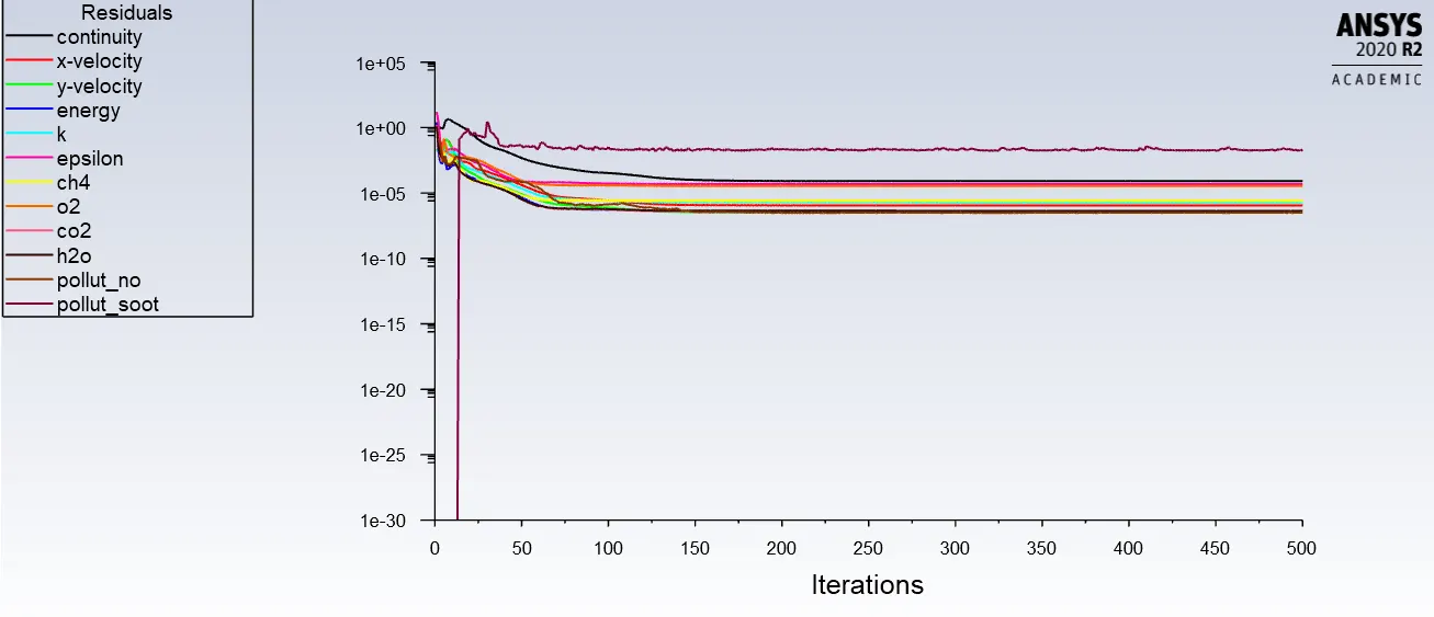
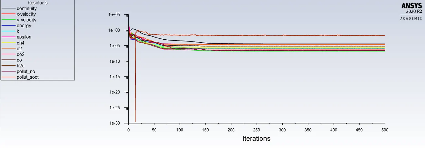
- Go to Solving > select Hybrid Initialization > Run the calculation for 500 iterations.
- Create necessary contours, planes to show the Mass fraction of CO,O2,H2O,CH4,NO,SOOT etc.
- For all the parameters generate charts so that for each case average value is generated and the results are compared.
Points for Line probes at different locations:
| x | y | z | |
| Line No 1 | |||
|
Point-1 Point-2 |
0.018 0.018 |
0 0.0365706 |
0 0 |
| Line No 2 | |||
|
Point-1 Point-2 |
0.1 0.1 |
0 0.0365706 |
0 0 |
| Line No 3 | |||
|
Point-1 Point-2 |
0.2 0.2 |
0 0.0365706 |
0 0 |
| Line 4 | |||
|
Point-1 Point-2 |
0.35 0.35 |
0 0.0365706 |
0 0 |
| Line 5 | |||
|
Point-1 Point-2 |
0.45 0.45 |
0 0.0365706 |
0 0 |
Observations:
(Part-1 Mixture Methane-Air)
Case 1:
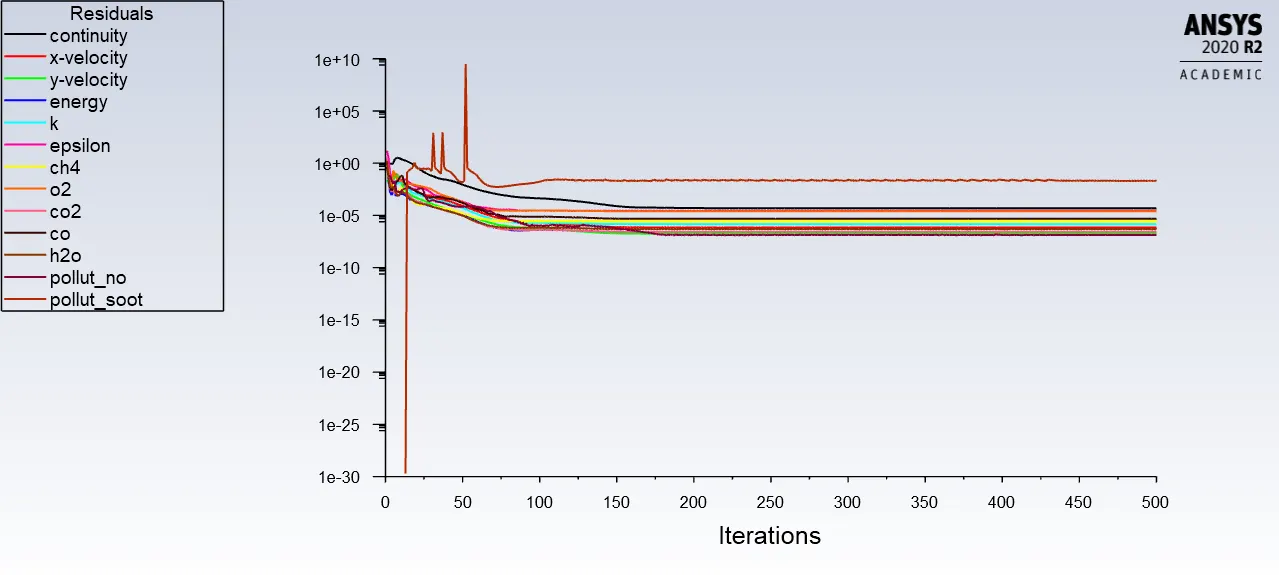
Residuals:
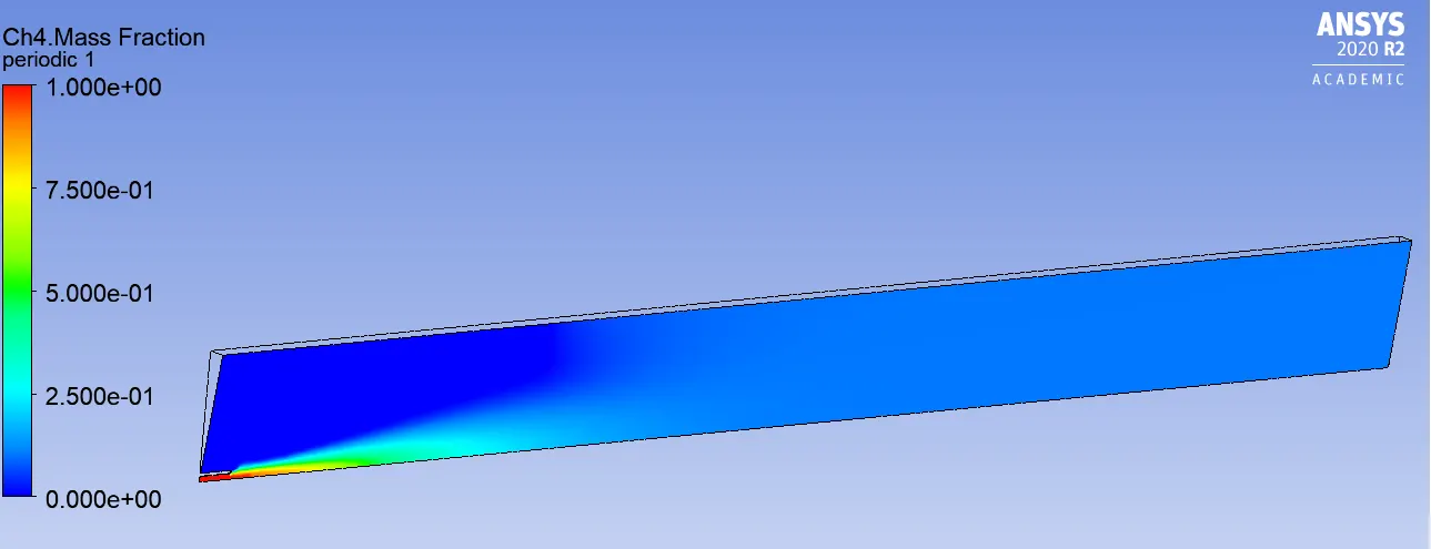
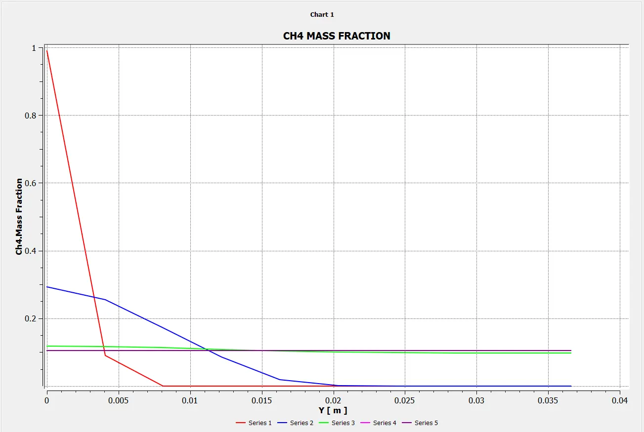
Mass Fraction of CH4
Line probes at different locations:
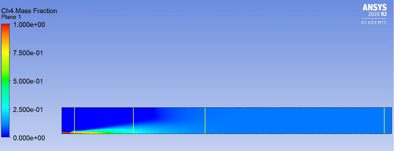
Chart:
Mass Fraction of CO2
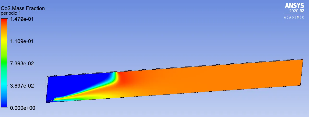
Line probes at different locations:
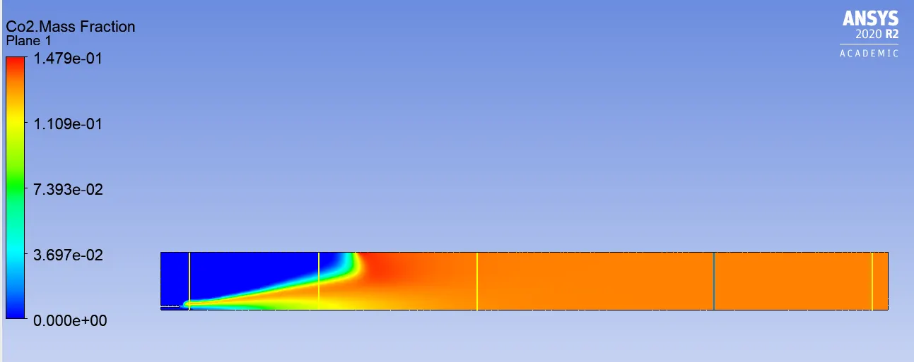
Chart:
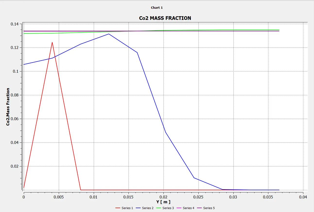
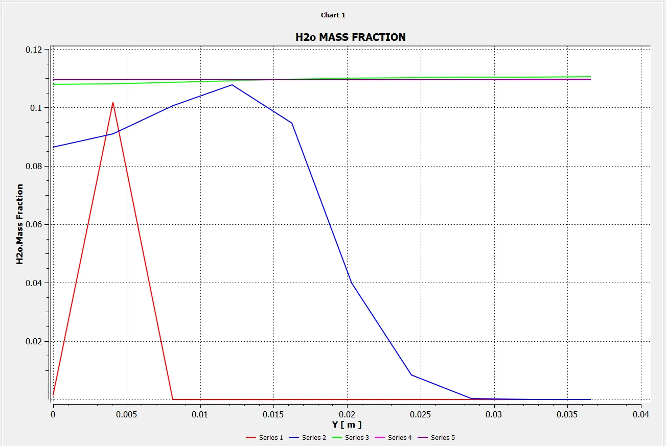
Mass Fraction of H2O
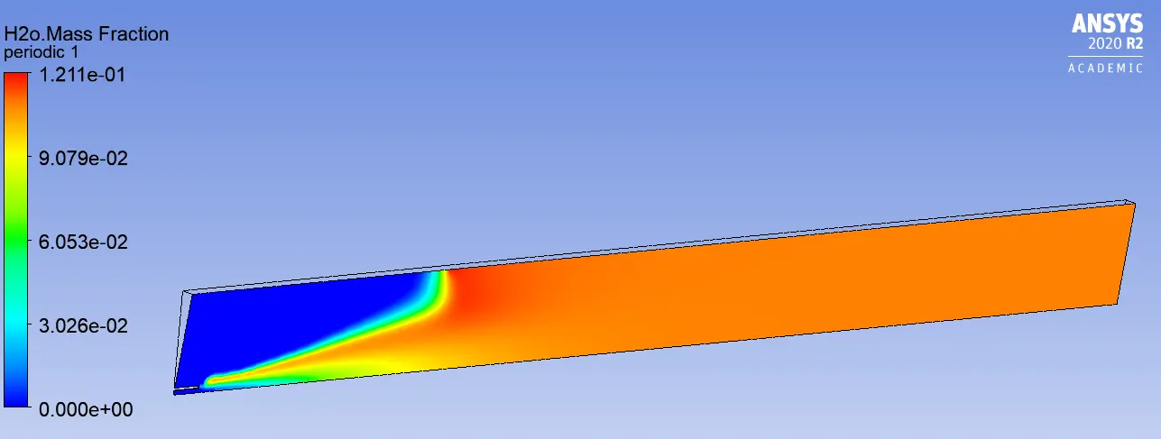
Line probes at different locations:
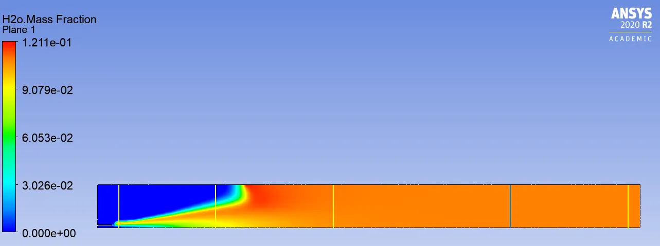
Chart:
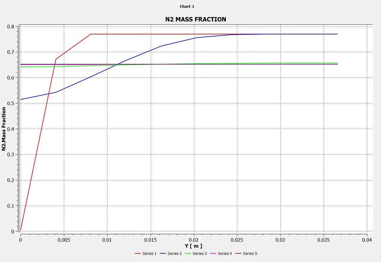
Mass Fraction of N2
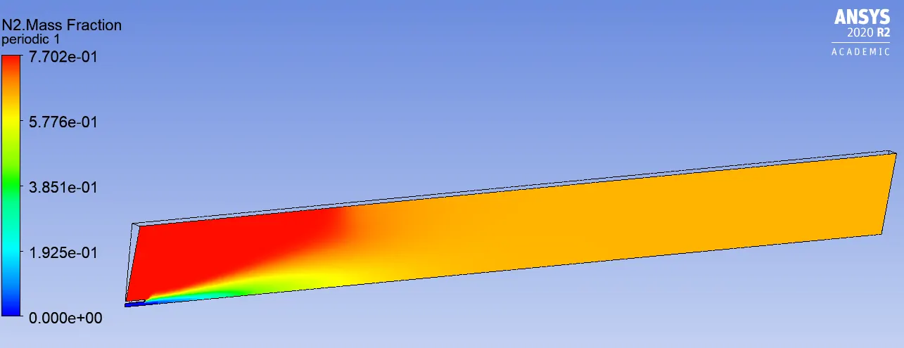
Line probes at different locations:
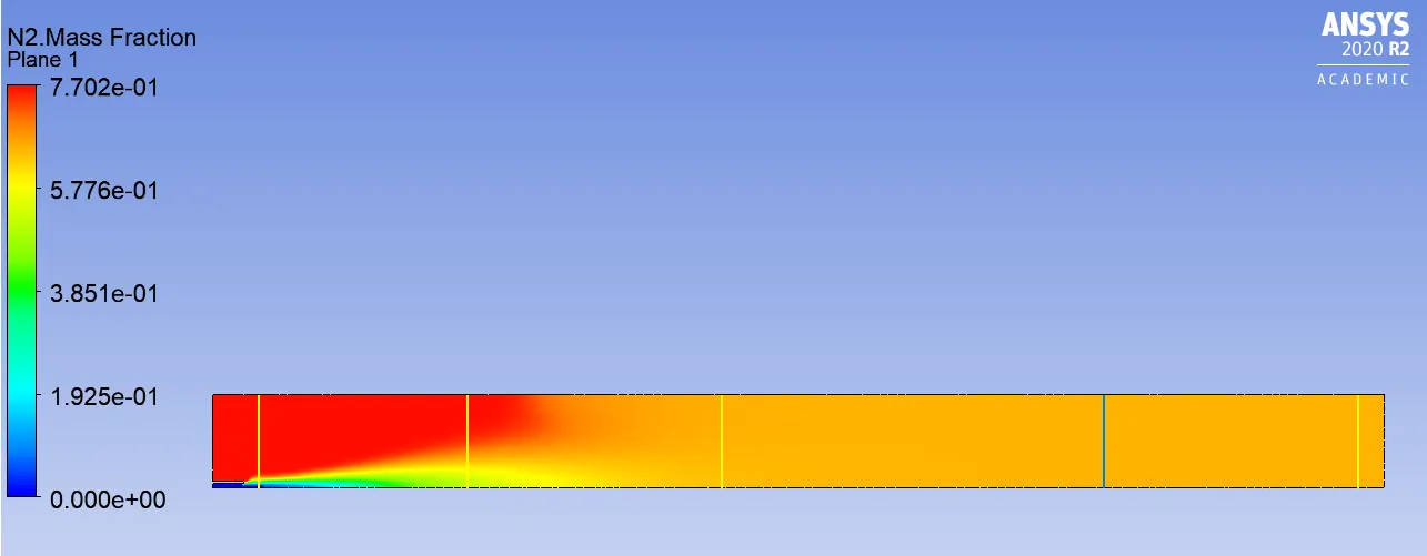
Chart:
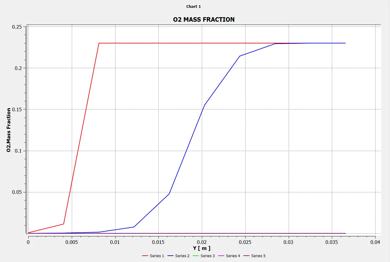
Mass Fraction of O2
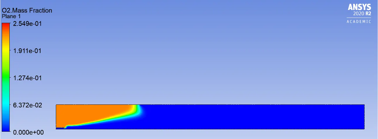
Line probes at different locations:
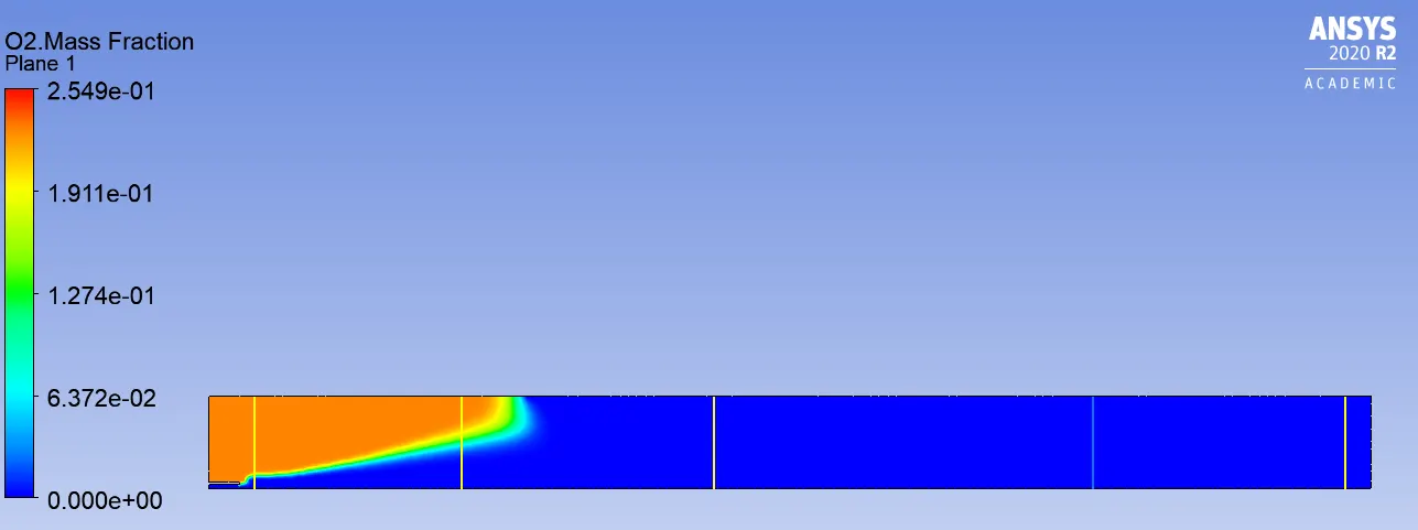
Chart:
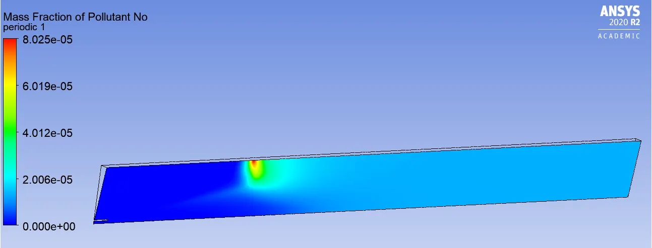
Mass Fraction of NOX:
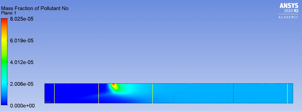
Line probes at different locations:
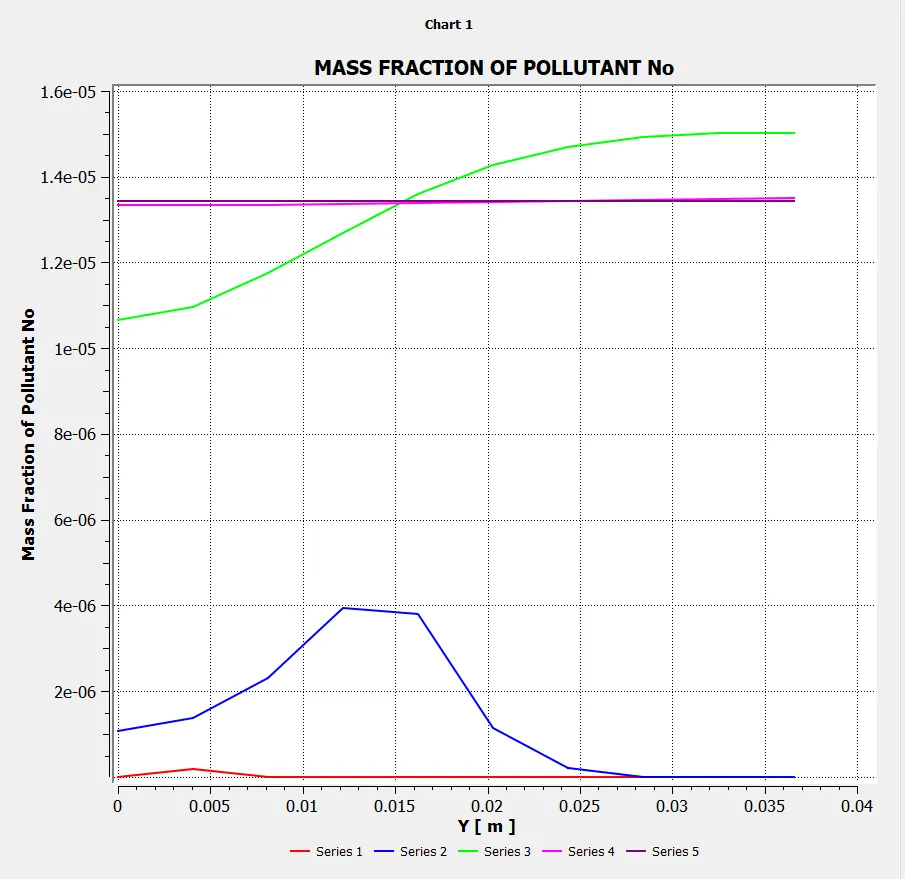
Charts:
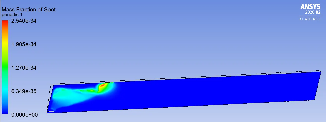
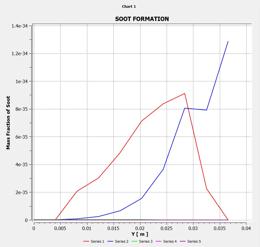
Mass Fraction of SOOT
Line probes at different locations:
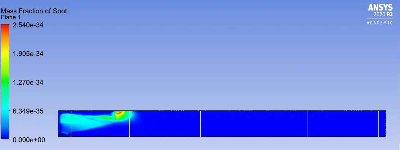
Chart:
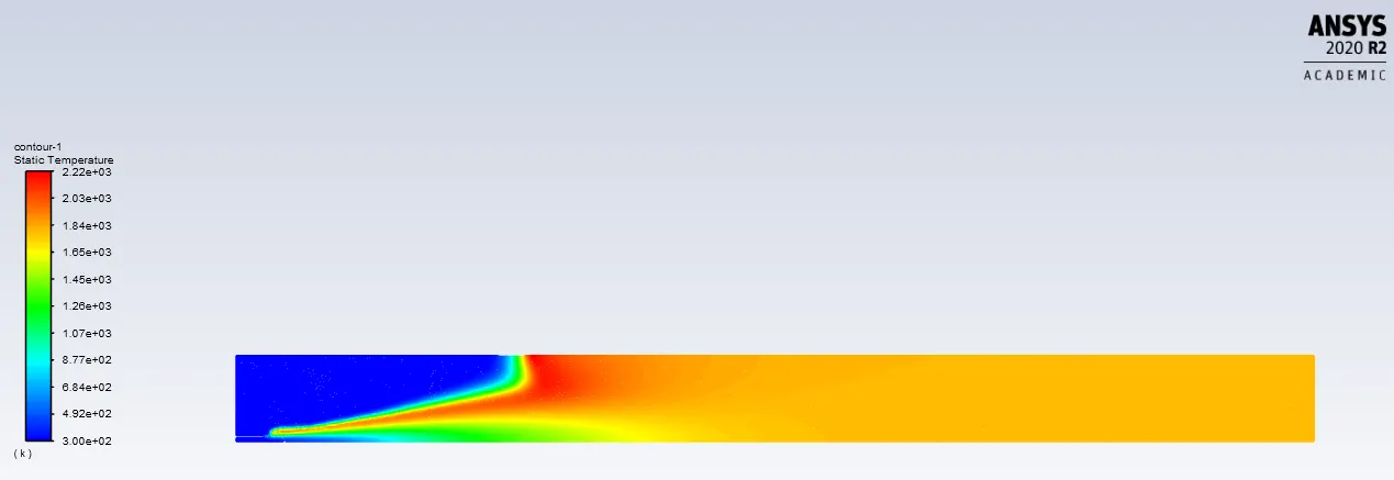
Temperature:
Animation:
Hero no additionl H2O is added the mixture.
Mass Fraction No(NOX) = 1.07E-05
Mass Fraction of SOOT = 8.76E-36
Observations:
(Part-2 Mixture Methane -Air-2step)
Adding the water content in the fuel from 5% to 30% by mole.
Boundary Conditions-
In setting up Physics > Boundary Conditions > go to Fuel-Inlet > move to Species > here for all the cases add the water content in the fuel from 5% to 30% by mole i.e. change values of CH4 & H2O.
Case-1: (CH4=0.95 & H2O=0.05)
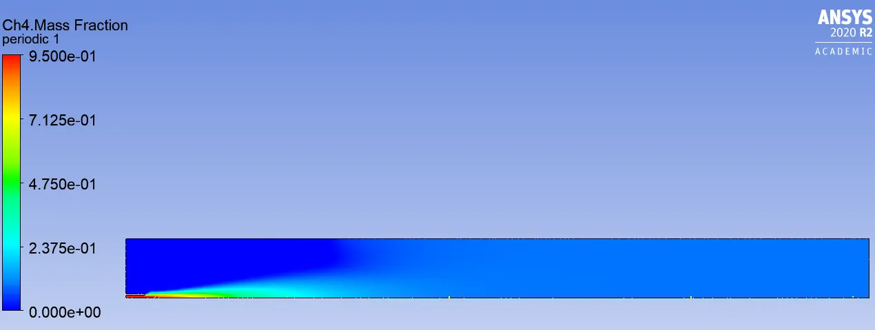
Mass Fraction of CH4
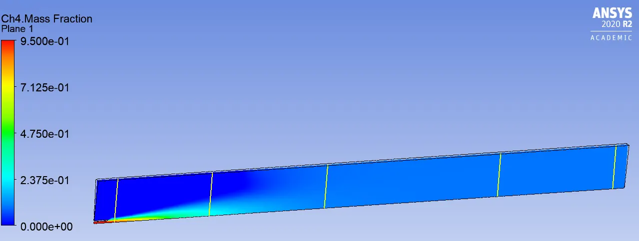
Line probes at different locations:
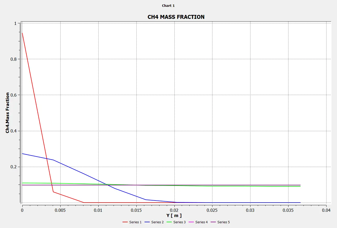
Charts:
Mass Fraction of CO2
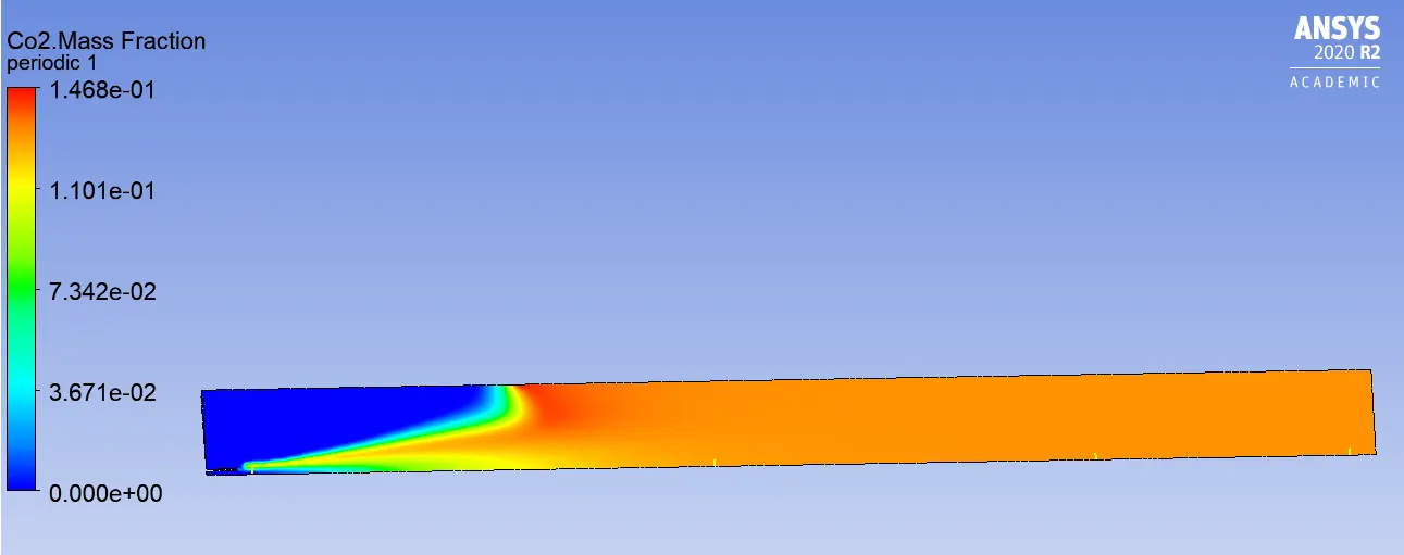
Line probes at different locations:
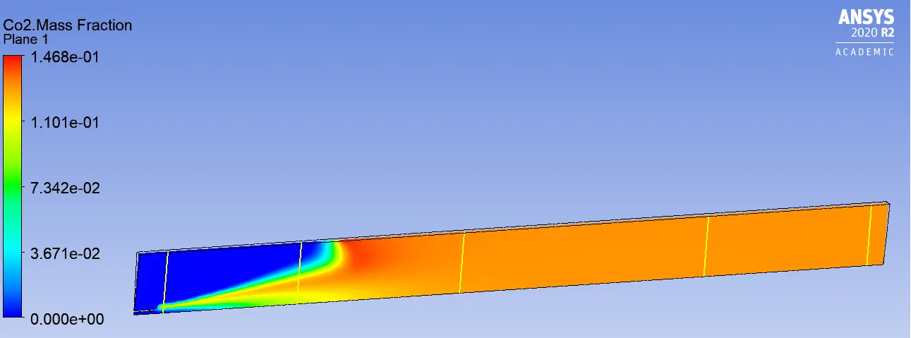
Charts:
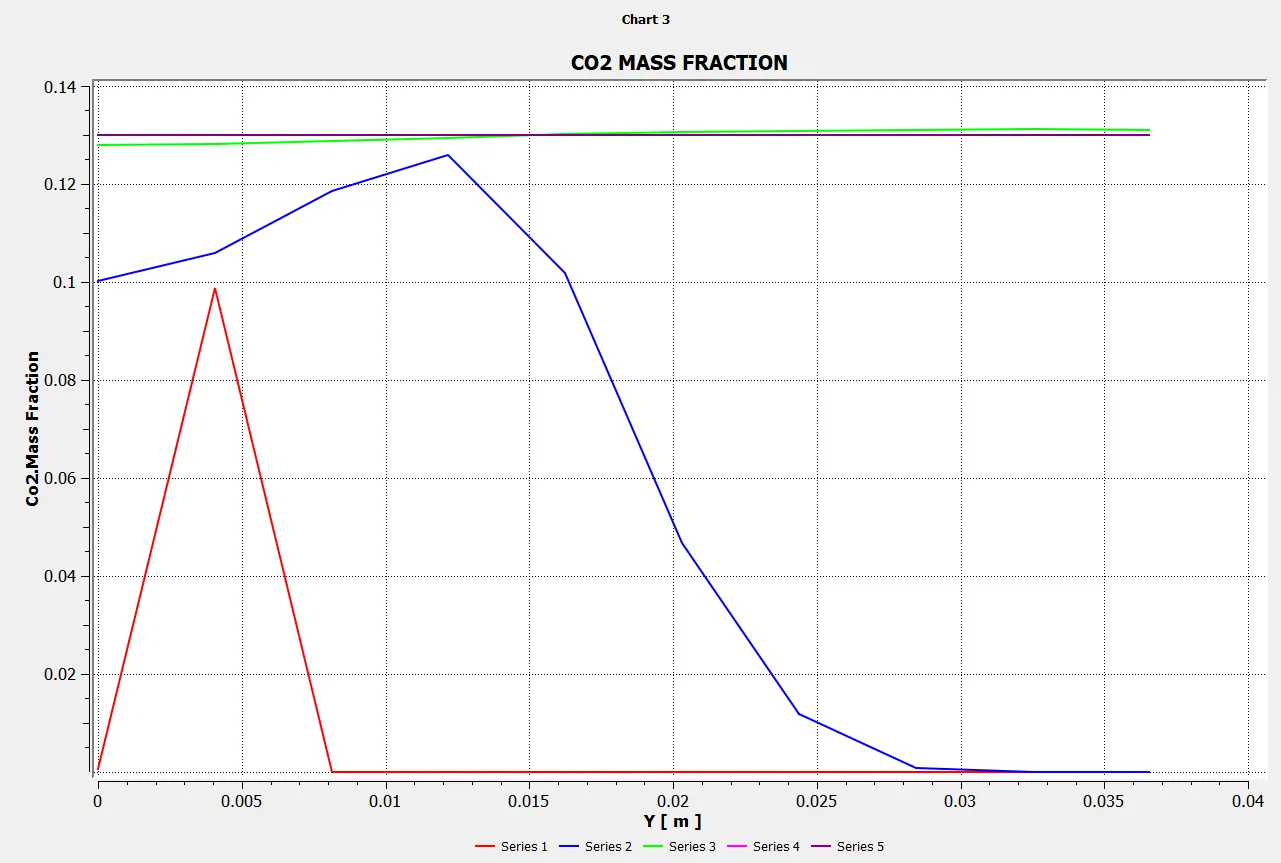
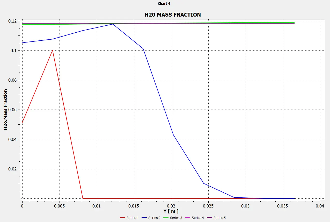
Mass Fraction of H2O
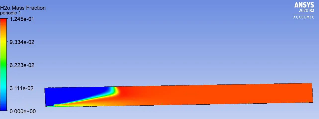
Line probes at different locations:
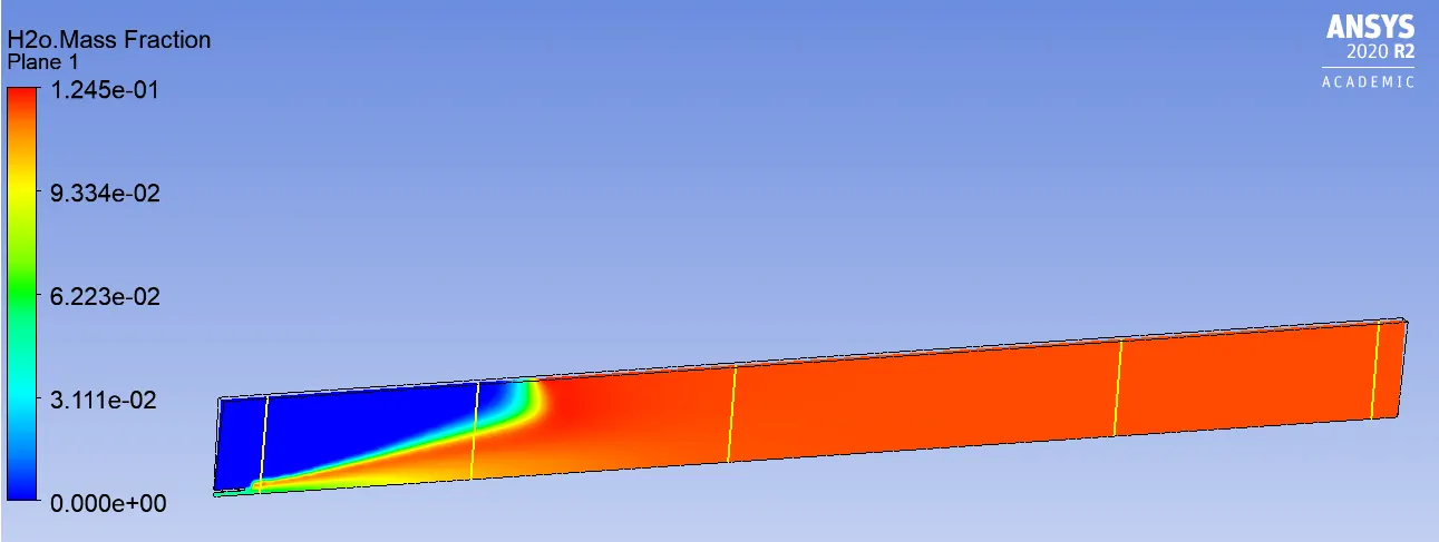
Chart:
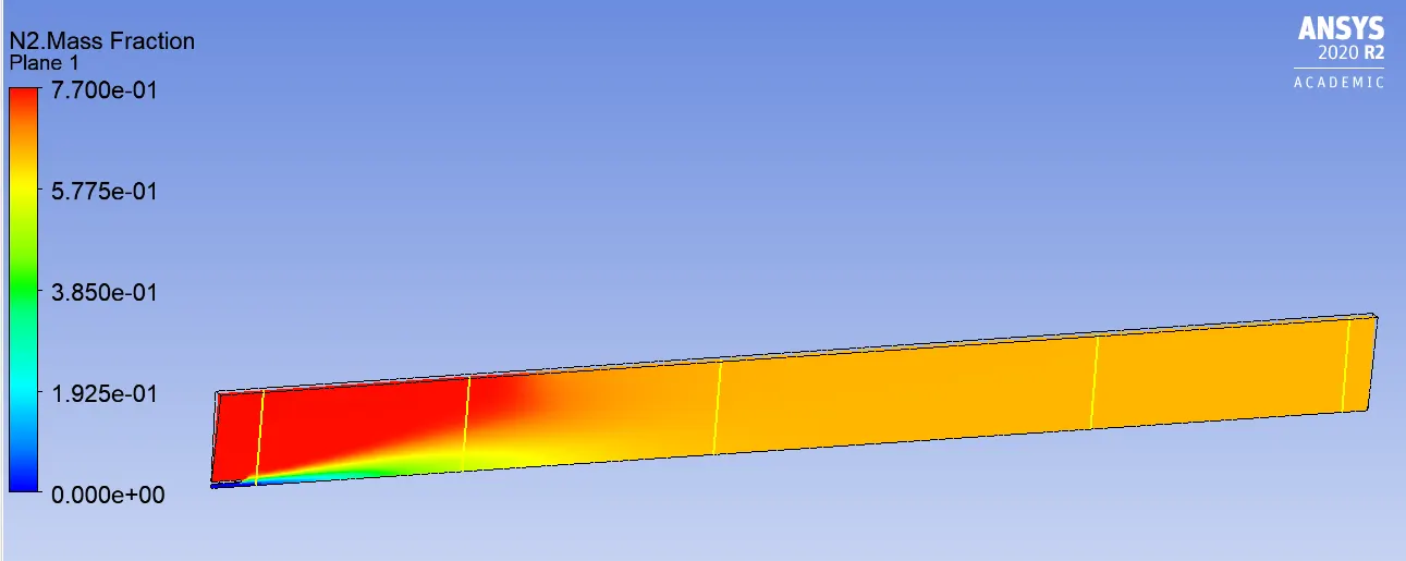
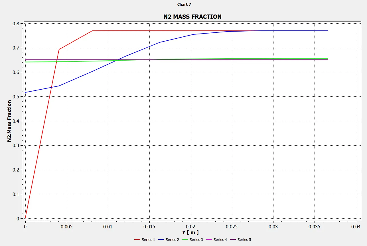
Mass Fraction of N2
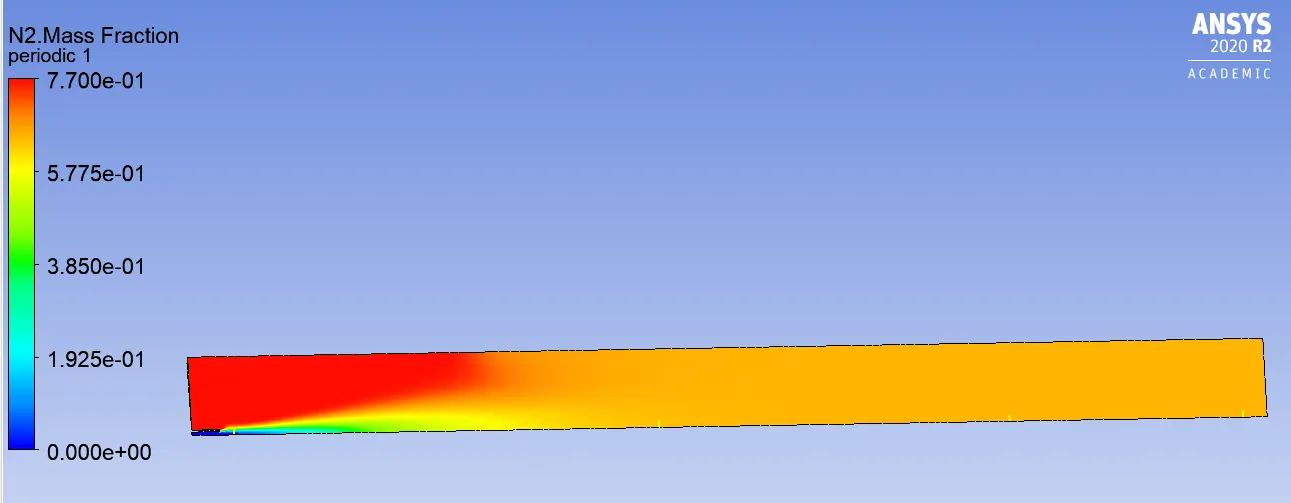
Line probes at different locations:
Charts:
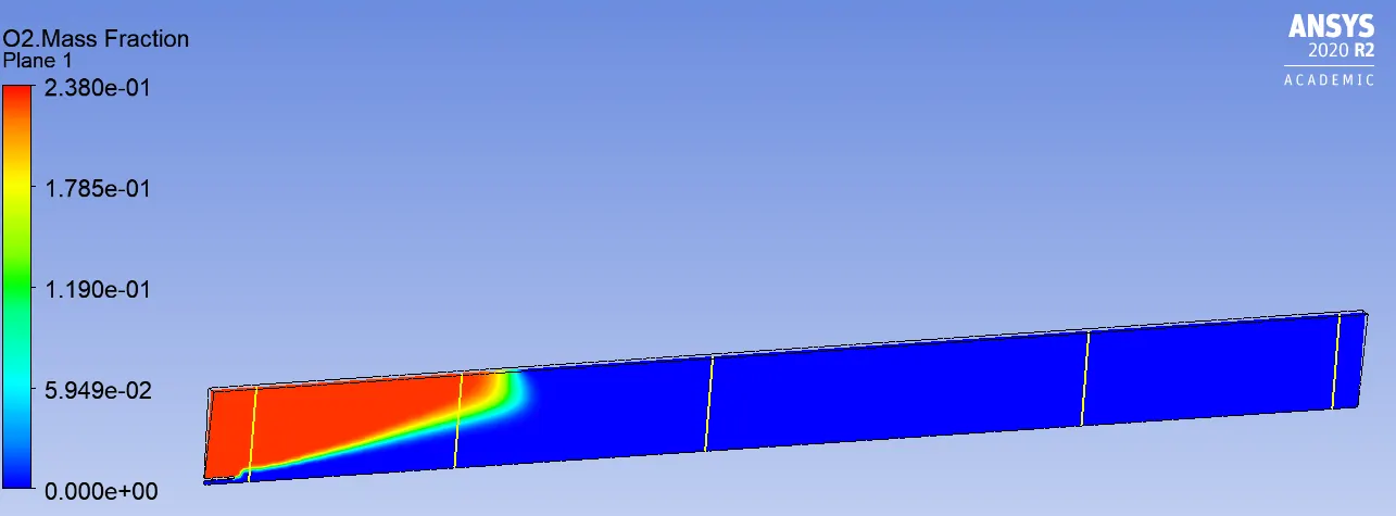
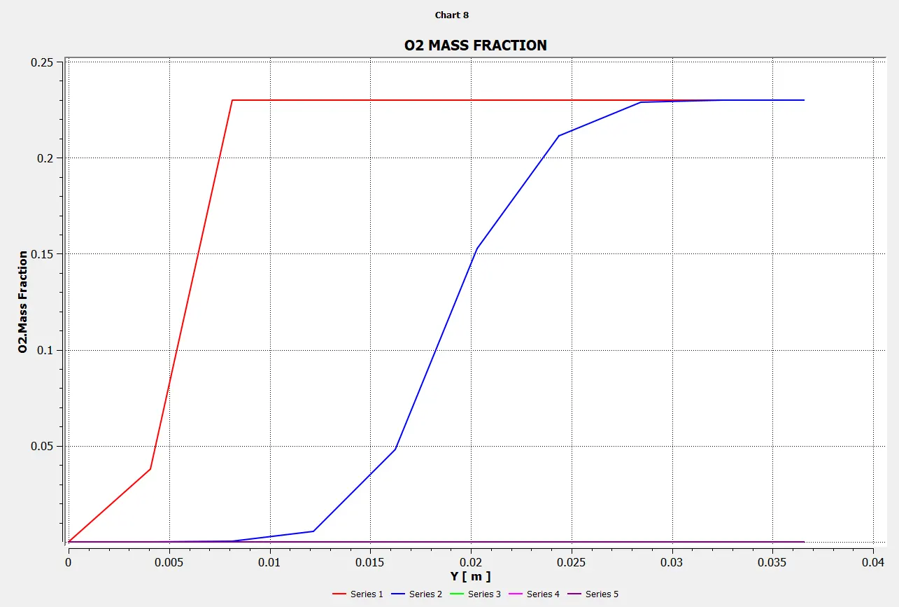
Mass Fraction of O2
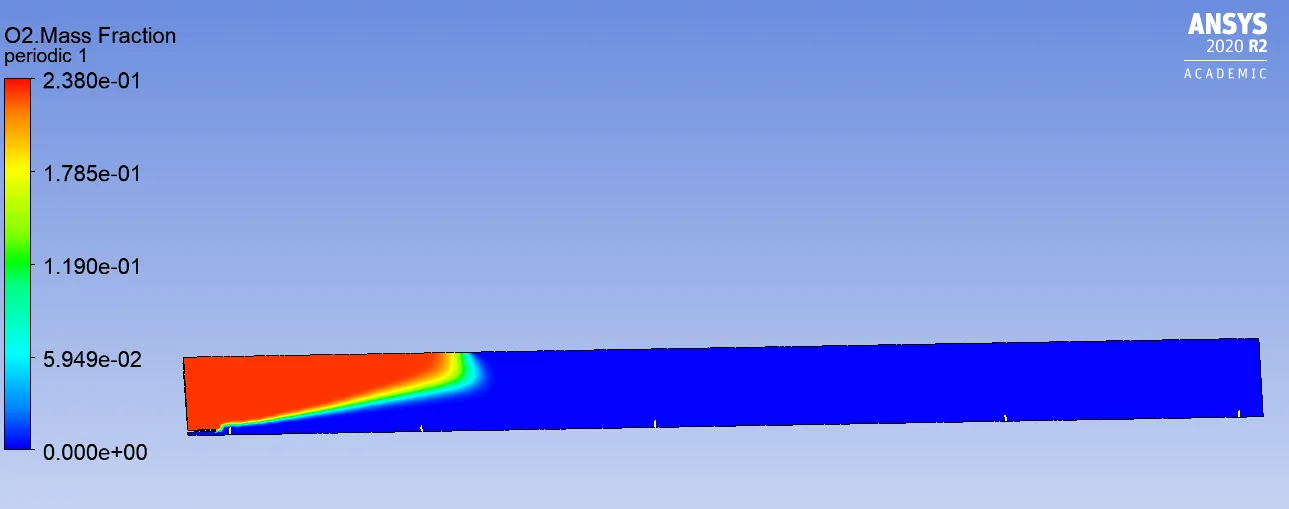
Line probes at different locations:
Charts:
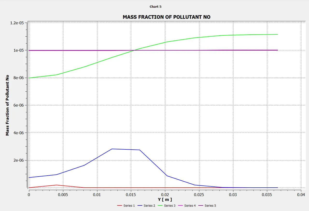
Mass Fraction of NOX
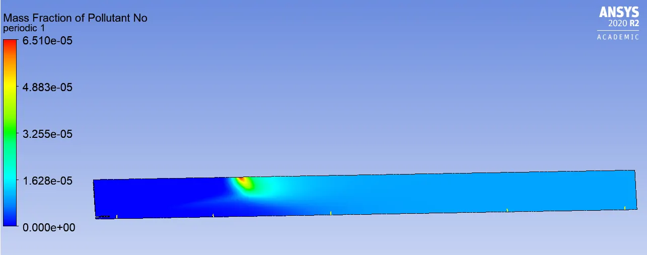
Line probes at different locations:
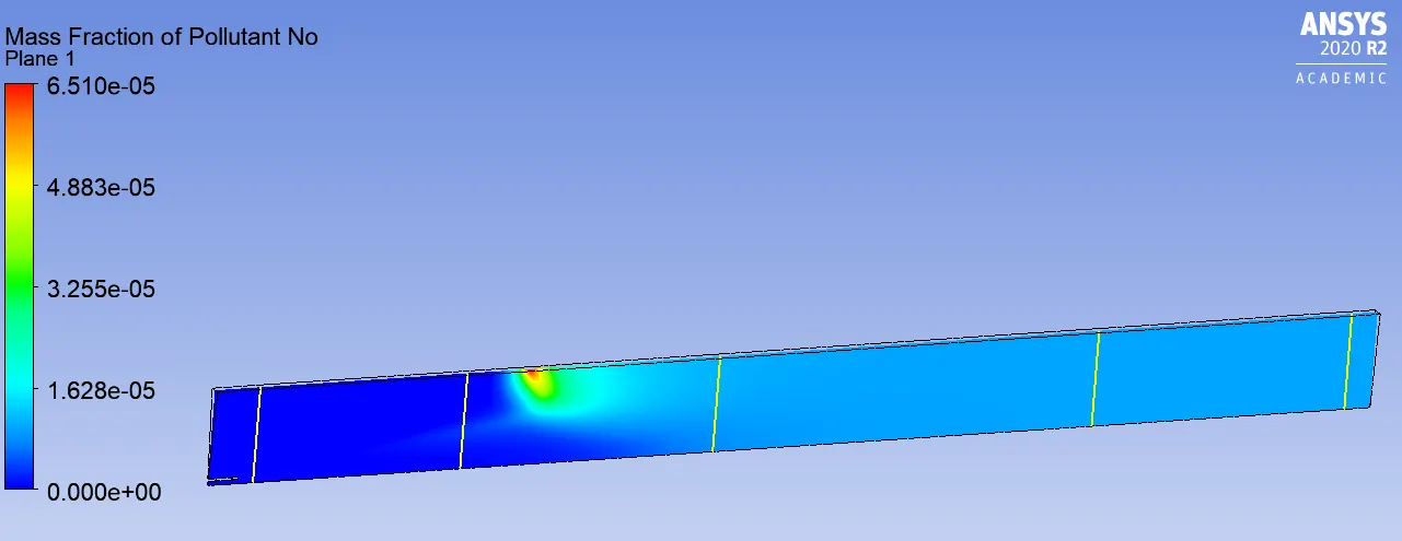
Charts:
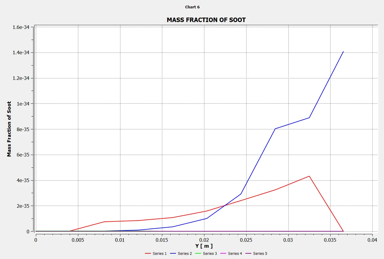
Mass Fraction of SOOT
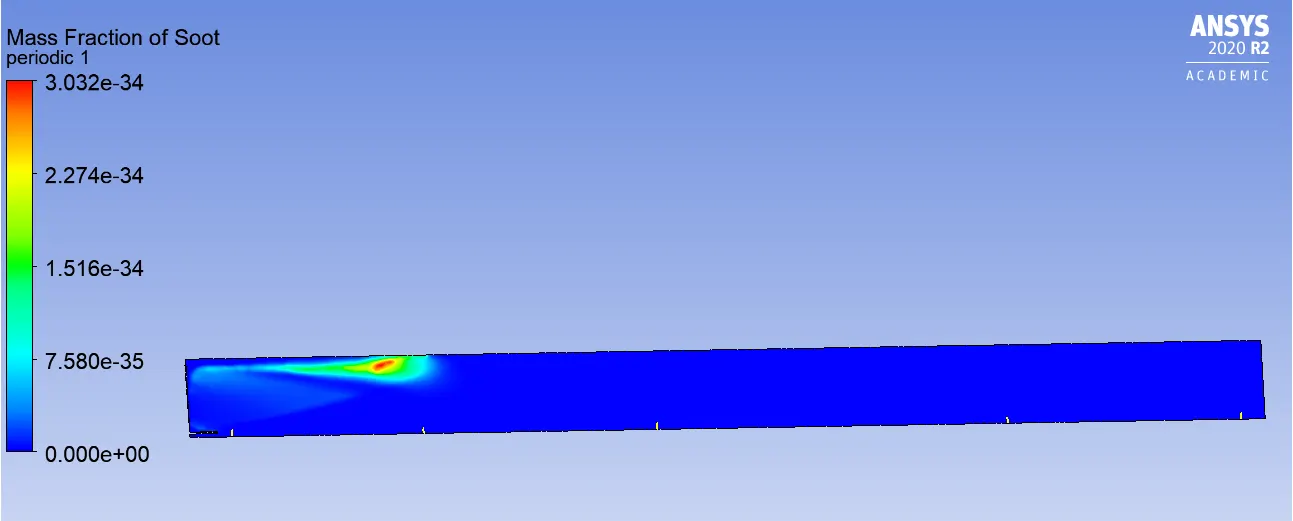
Line probes at different locations:
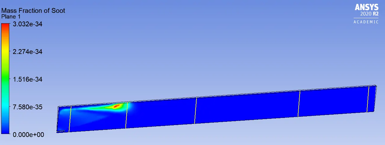
Chart:
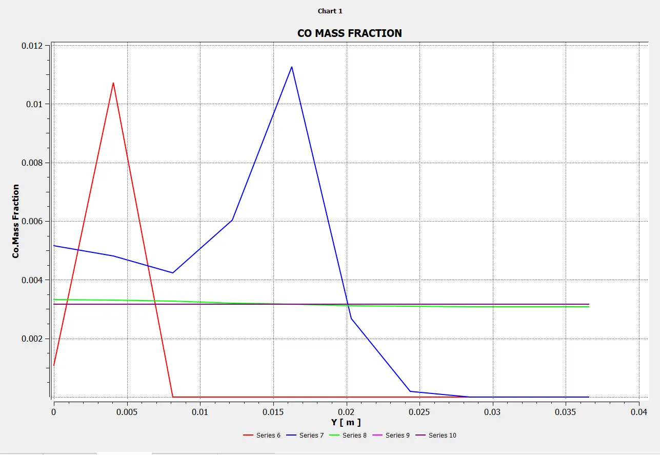
Mass Fraction of CO
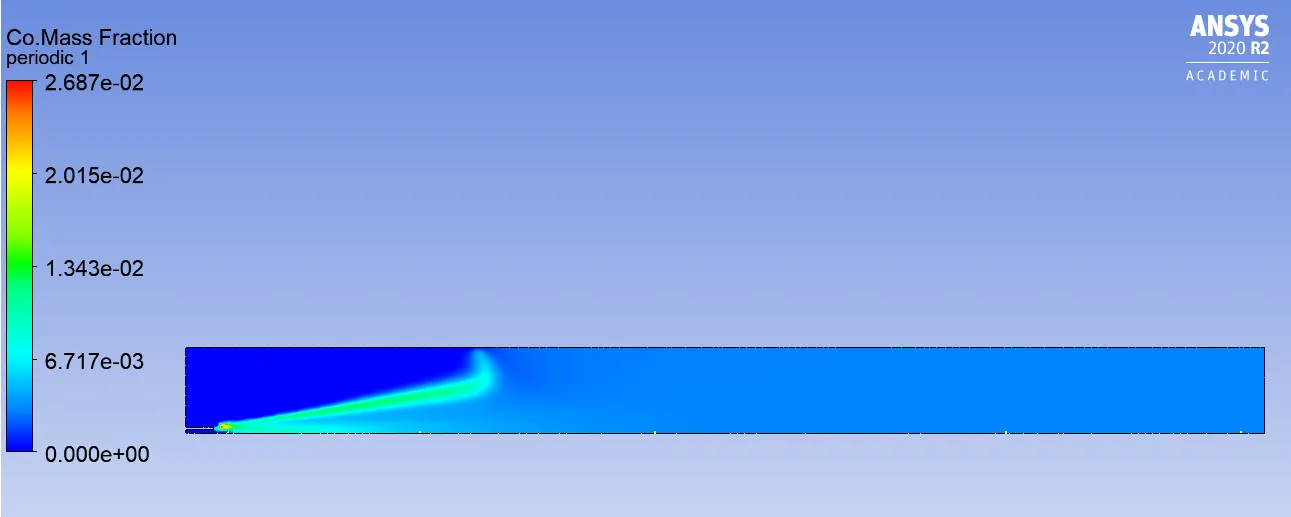
Line probes at different locations:
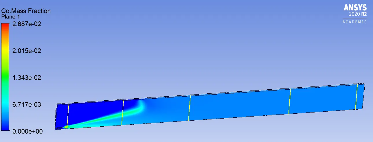
Chart:
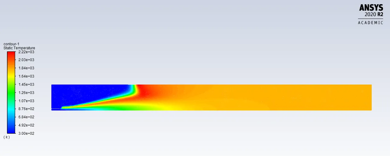
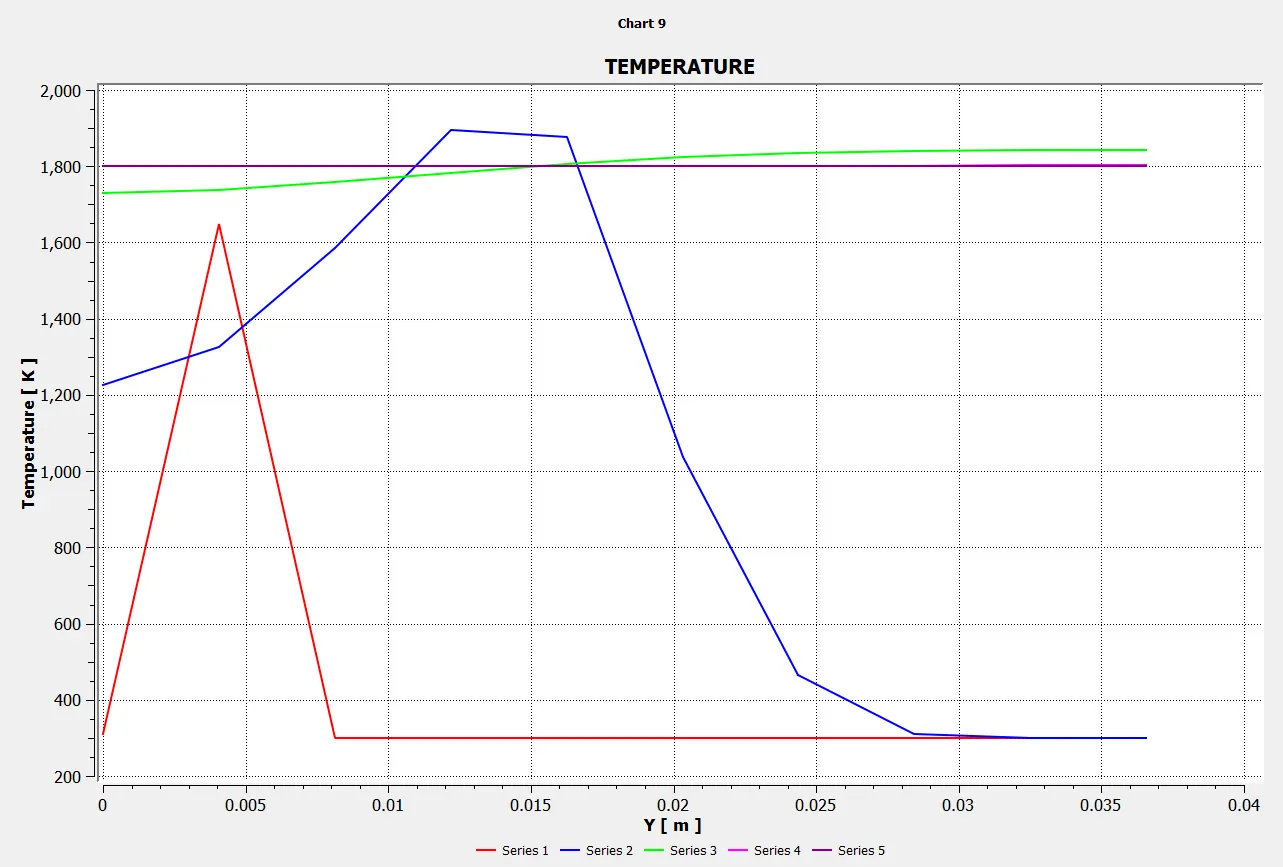
Temperature:
Animation:
Case-2: (CH4=0.9 & H2O=0.1)
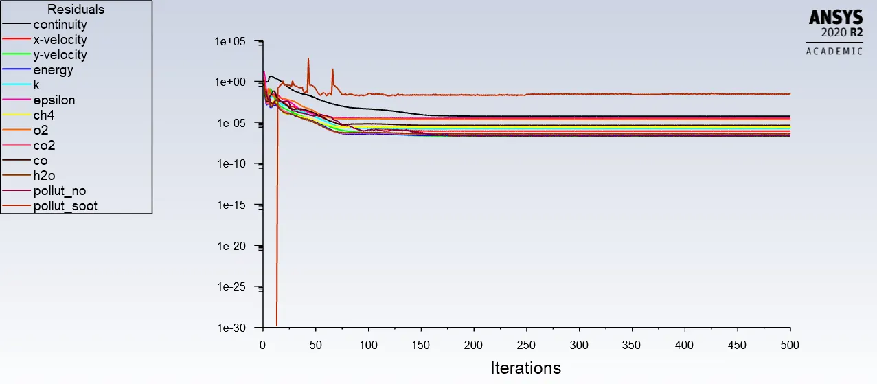
Mass Fraction of CH4
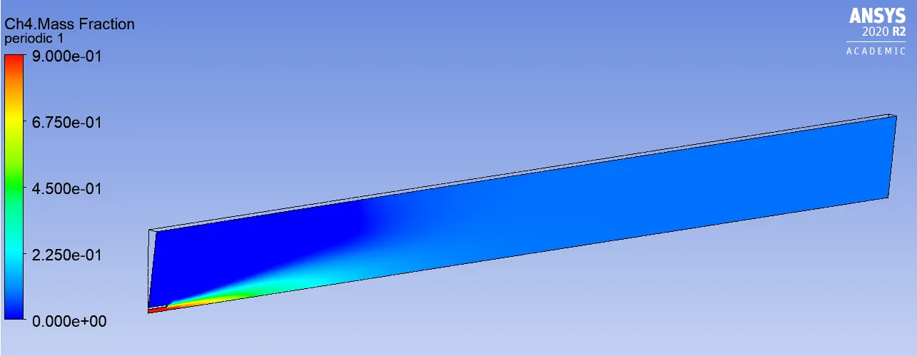
Line probes at different locations:
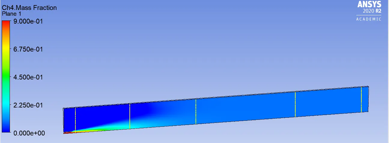
Chart:
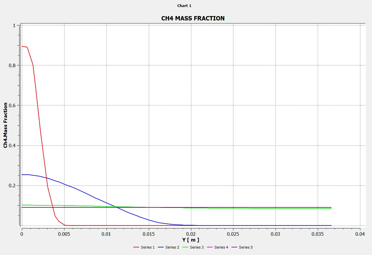
Mass Fraction of CO2
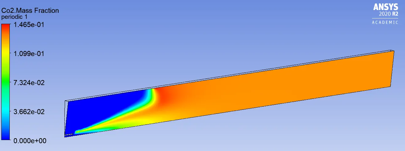
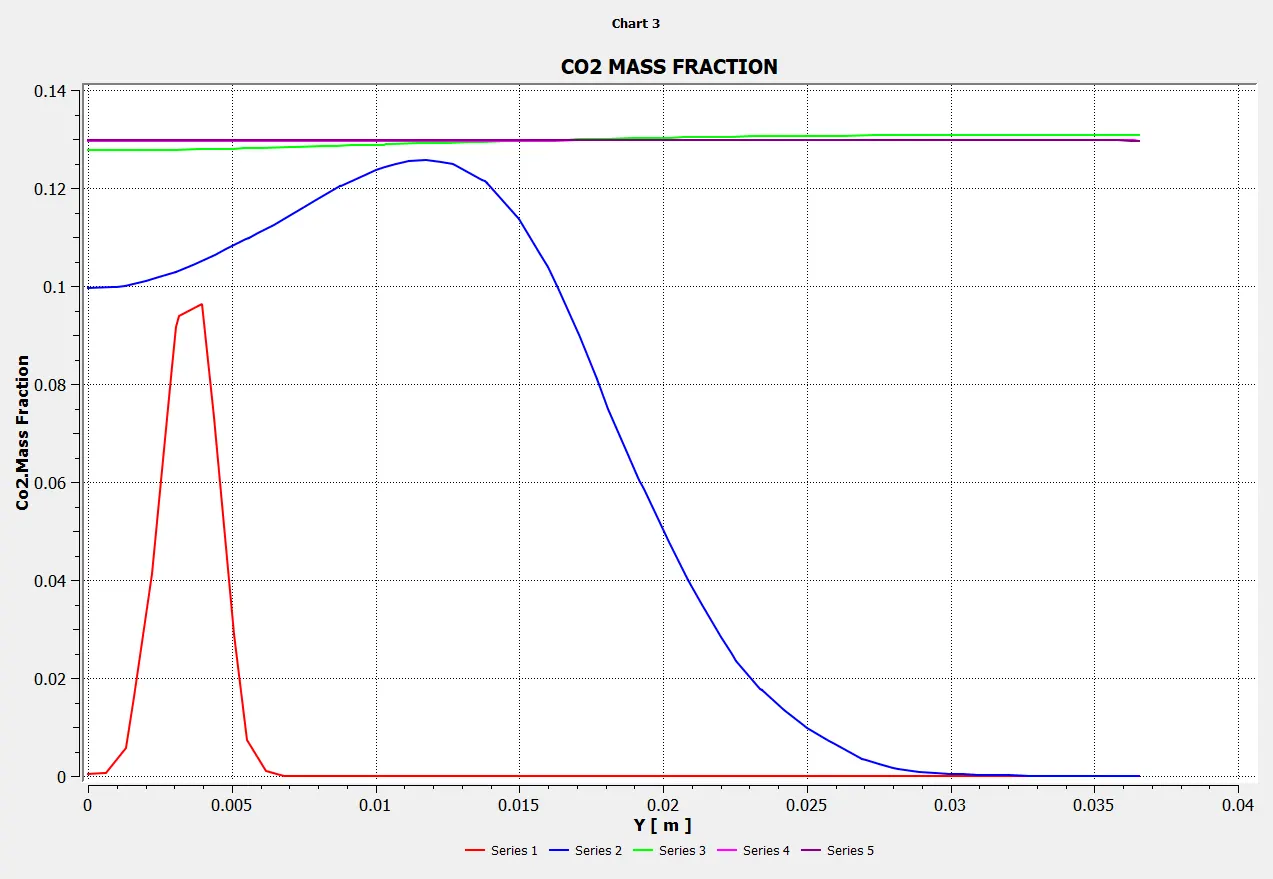
Line probes at different locations:
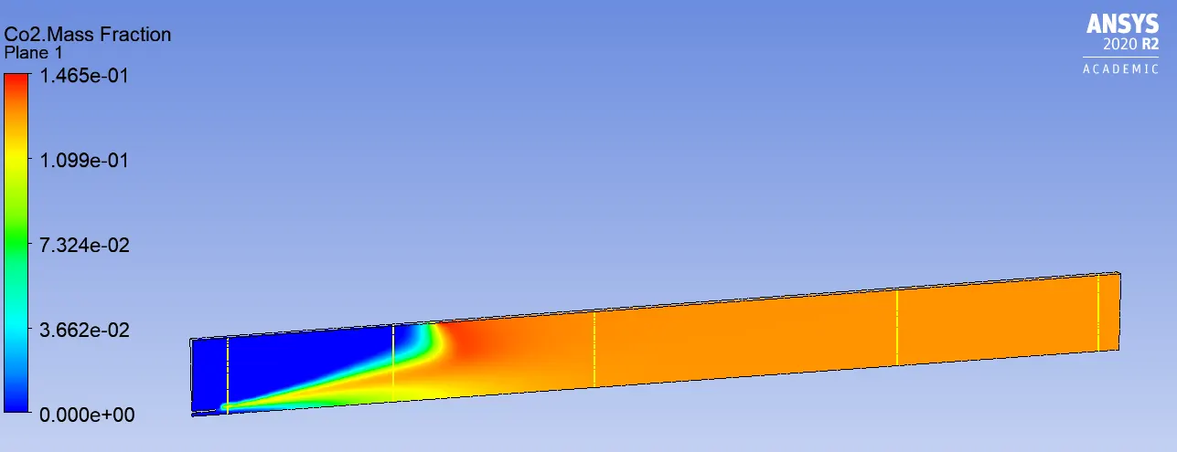
Chart:
Mass Fraction of H2O
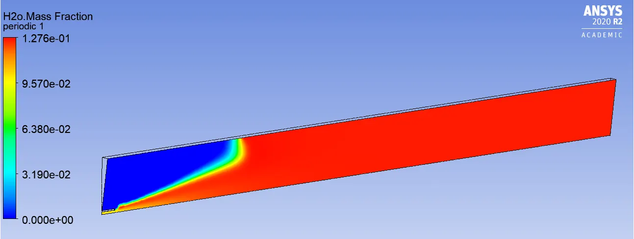
Line probes at different locations:
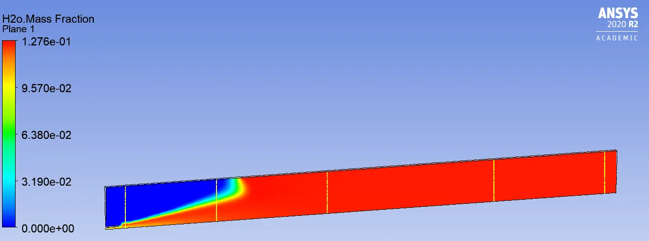
Chart:
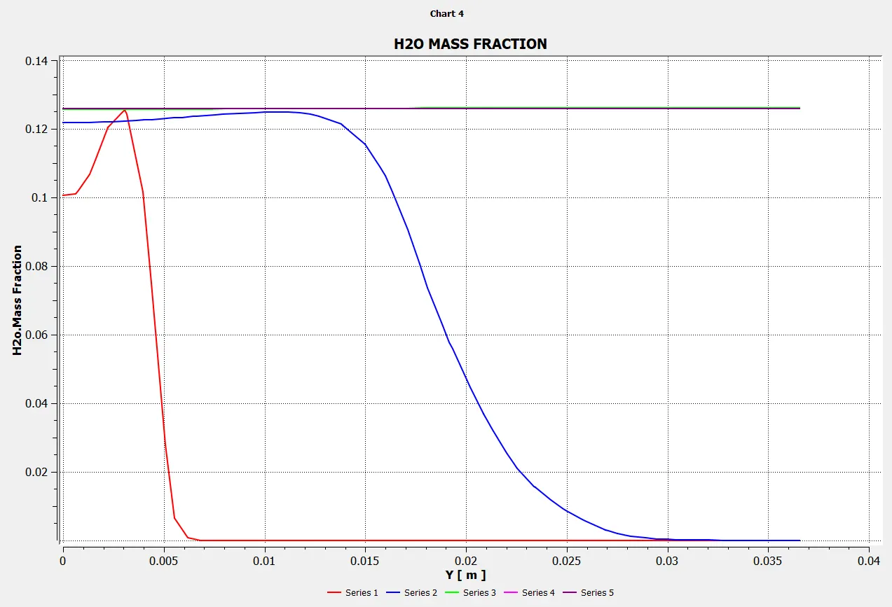
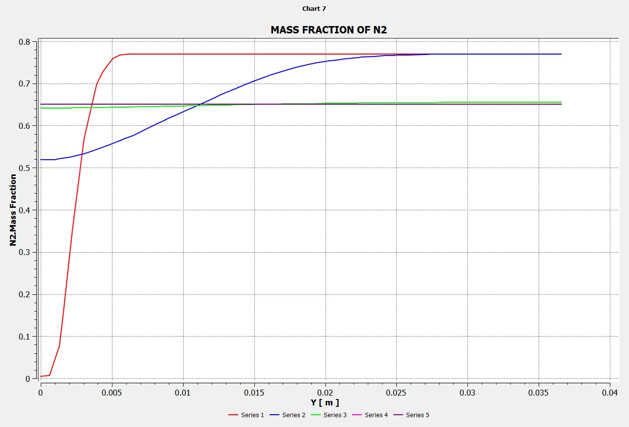
Mass Fraction of N2
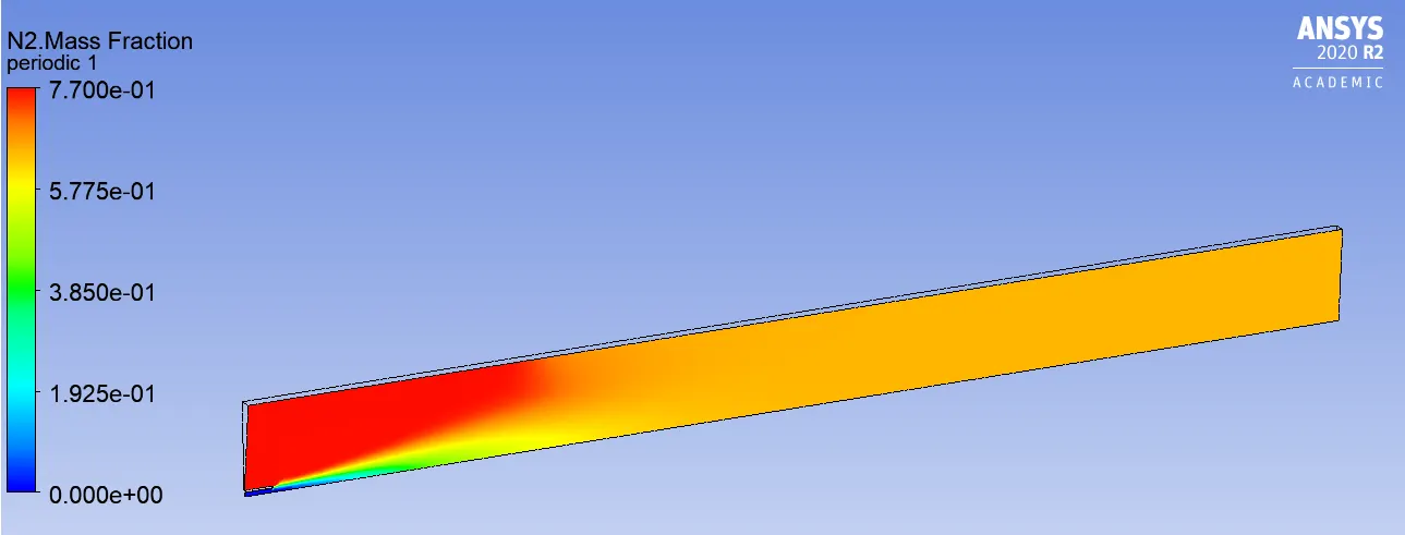
Line probes at different locations:
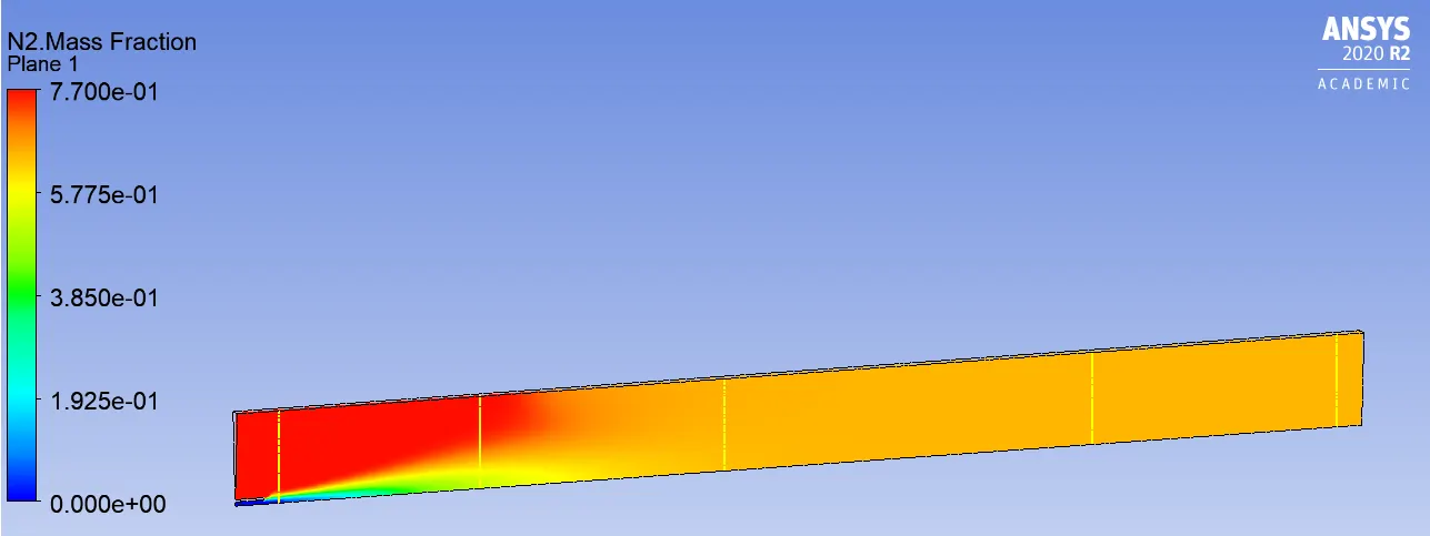
Chart:
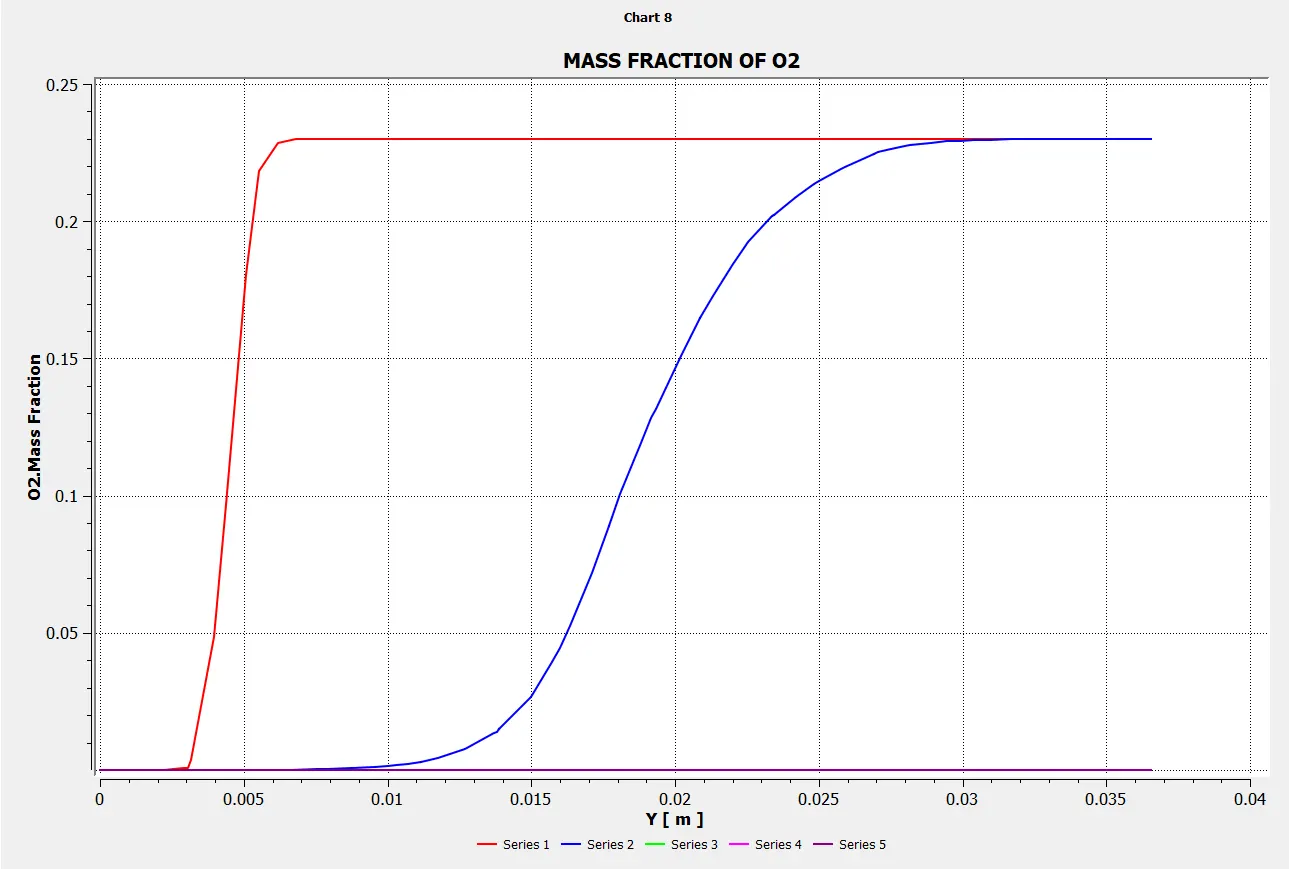
Mass Fraction of O2
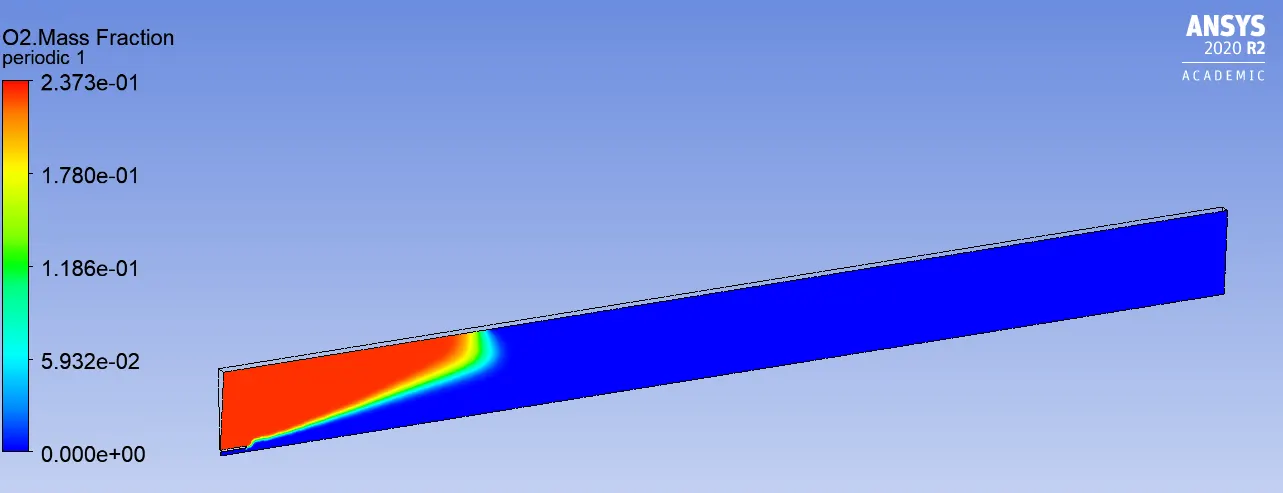
Line probes at different locations:
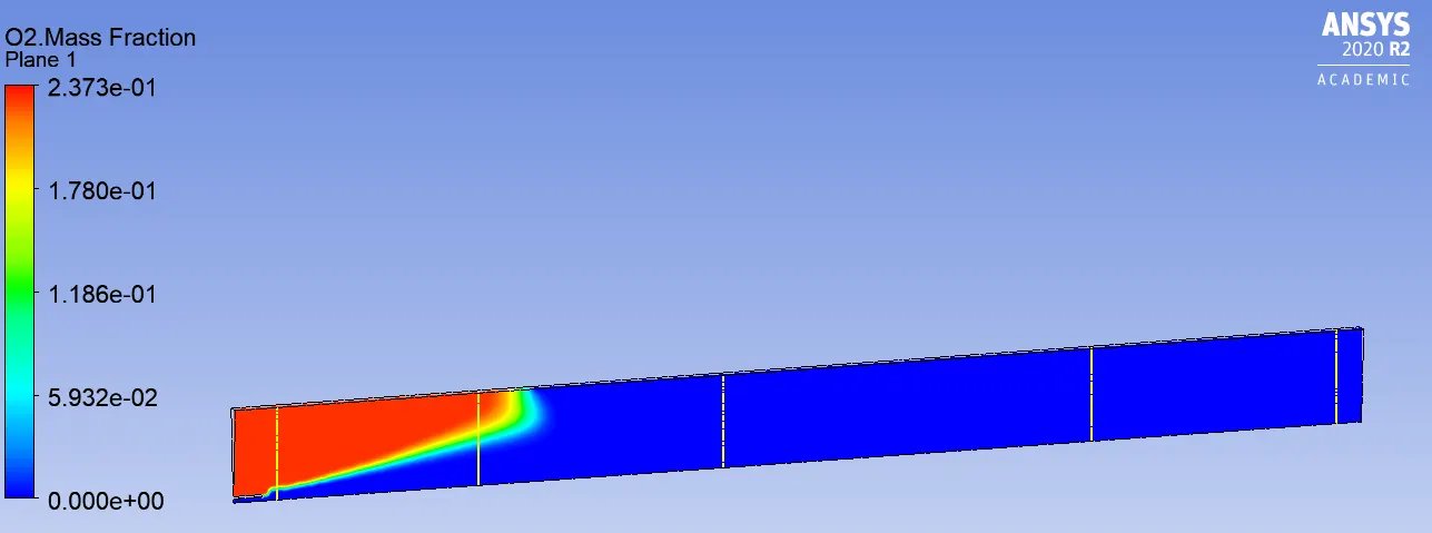
Chart:
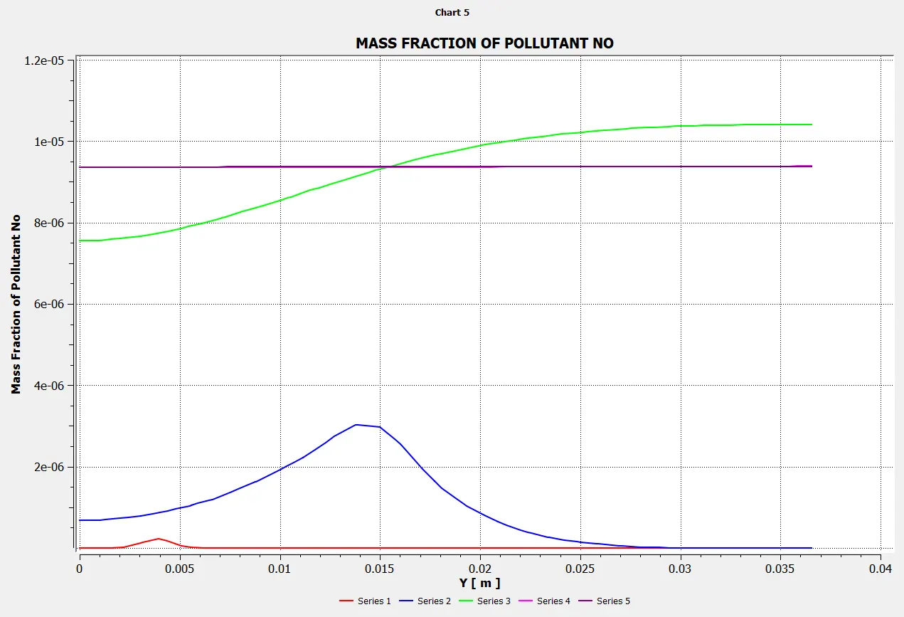
Mass Fraction of NOX
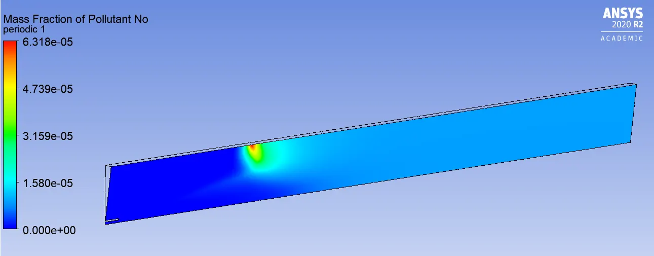
Line probes at different locations:
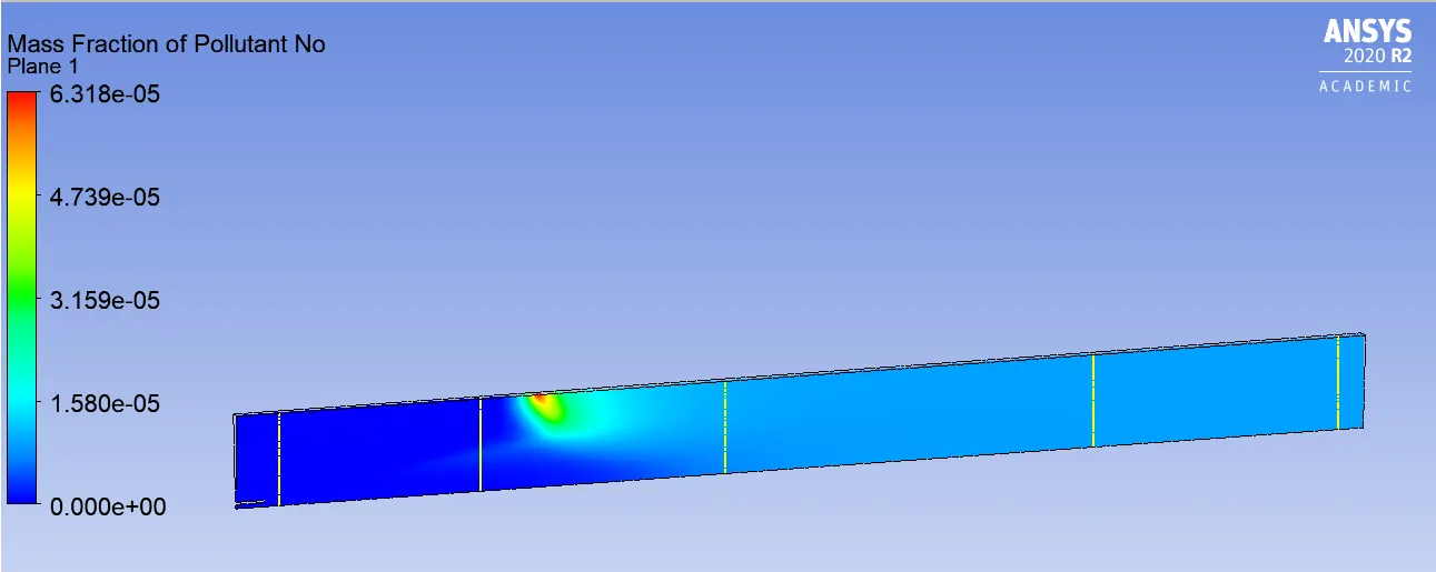
Chart:
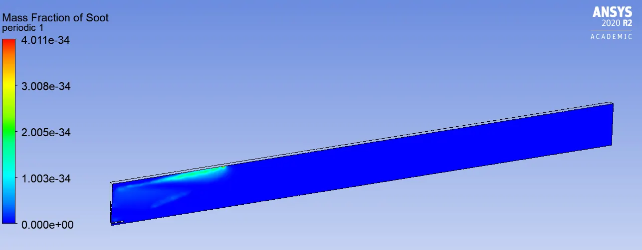
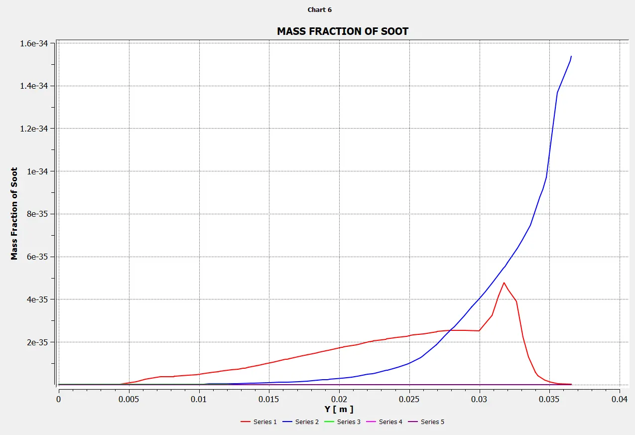
Mass Fraction of SOOT
Line probes at different locations:
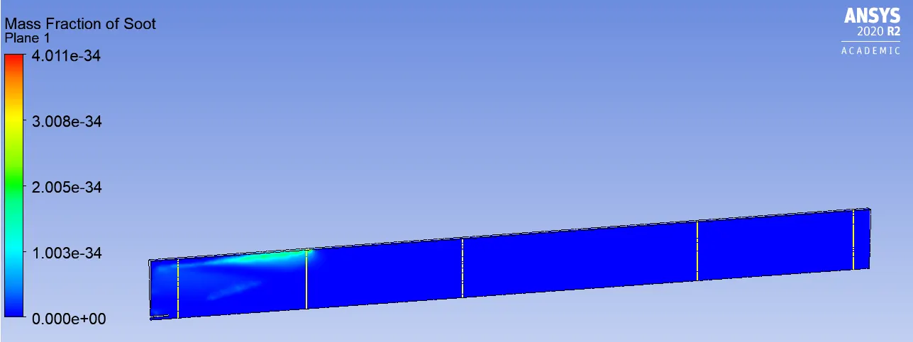
Chart:
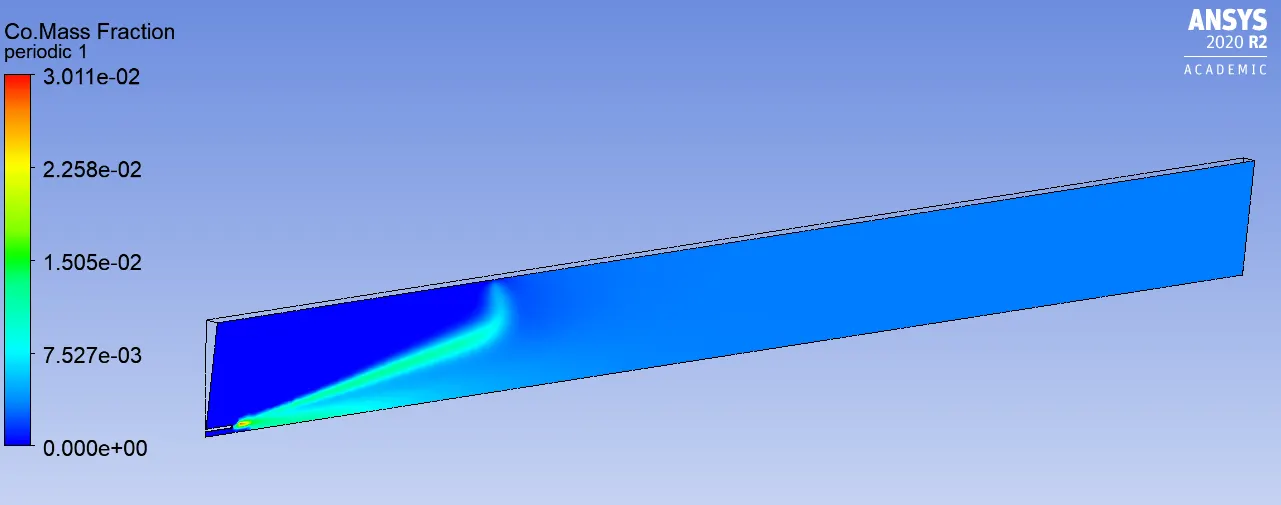
Mass Fraction of CO
Line probes at different locations:
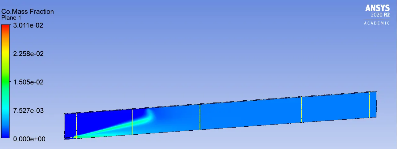
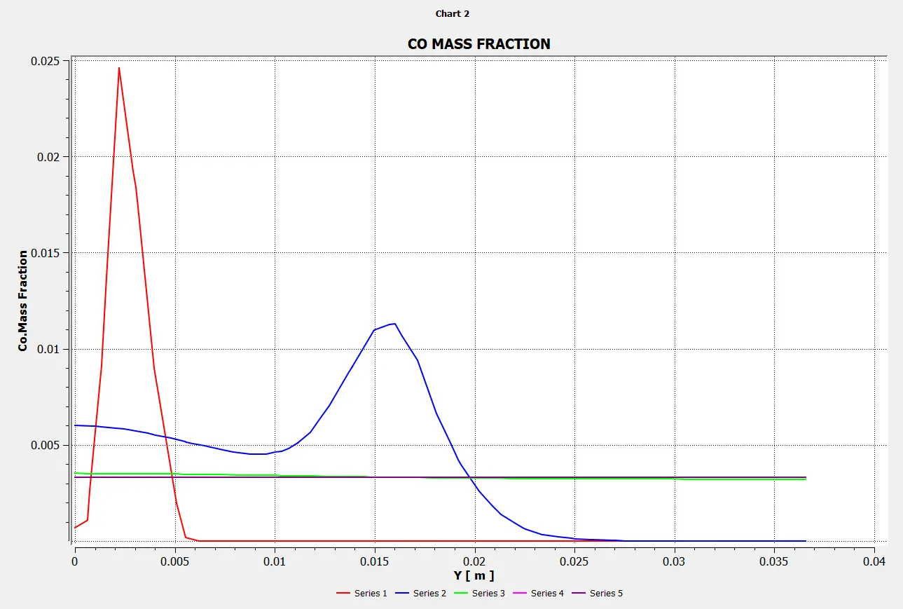
Chart:
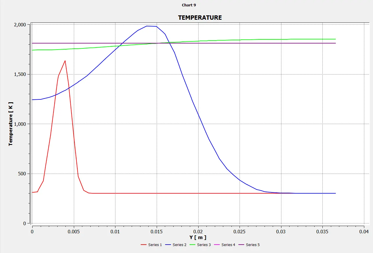
Temperature:
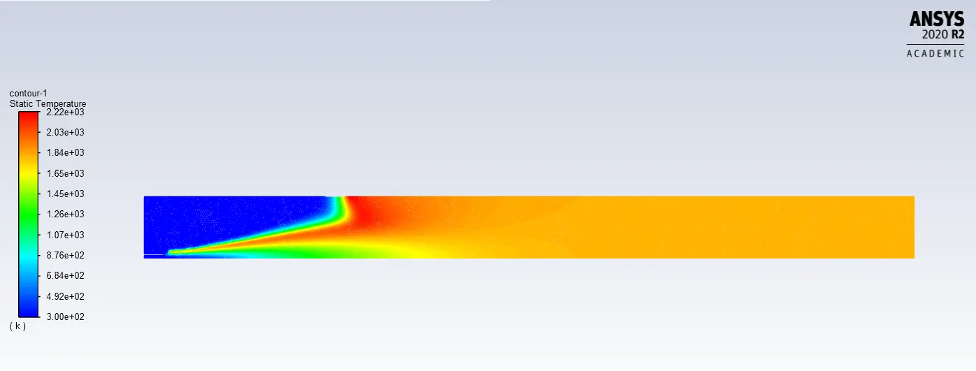
Chart:
Animation:
Case-3: (CH4=0.8 & H2O=0.2)
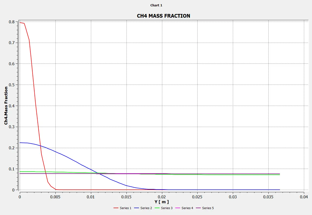
Mass Fraction of CH4
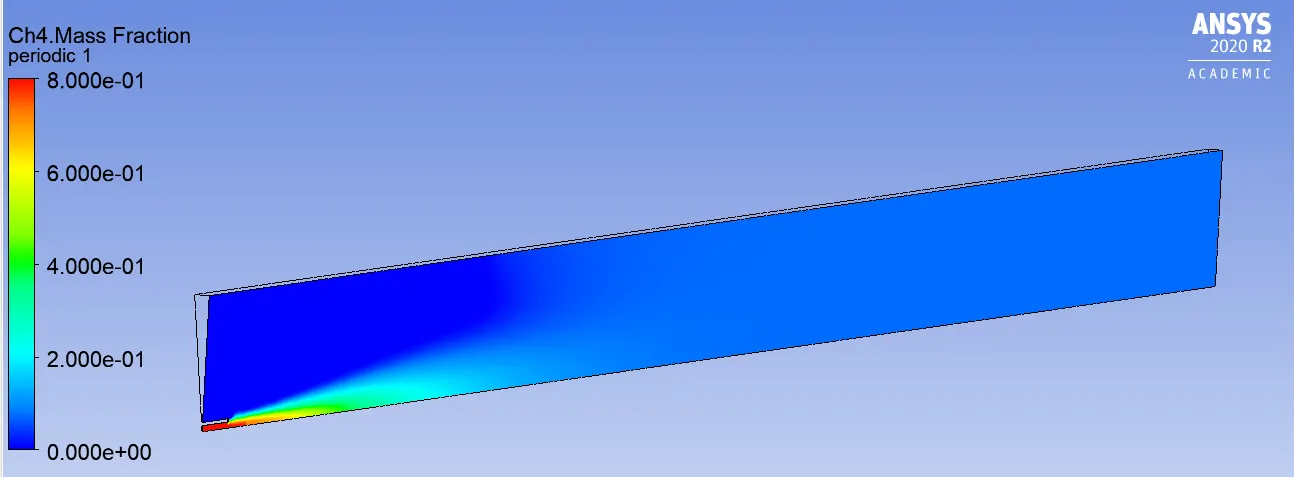
Line probes at different locations:
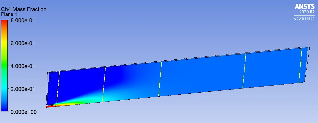
Chart:
Mass Fraction of CO2
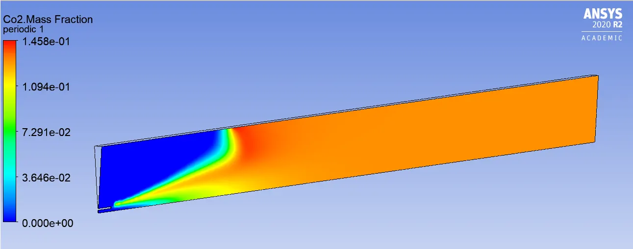
Line probes at different locations:
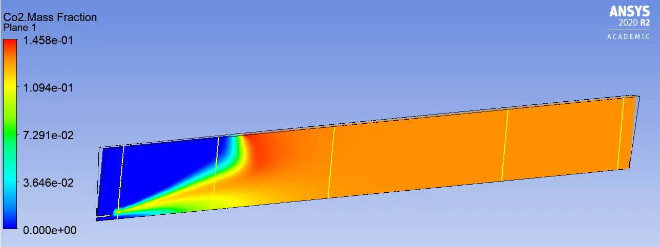
Chart:
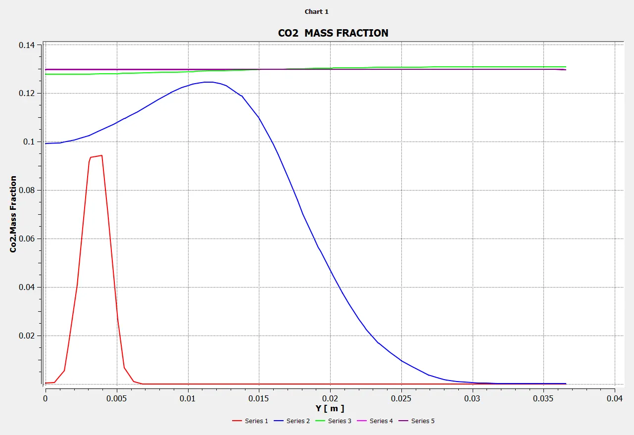
Mass Fraction of H2O
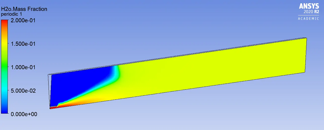
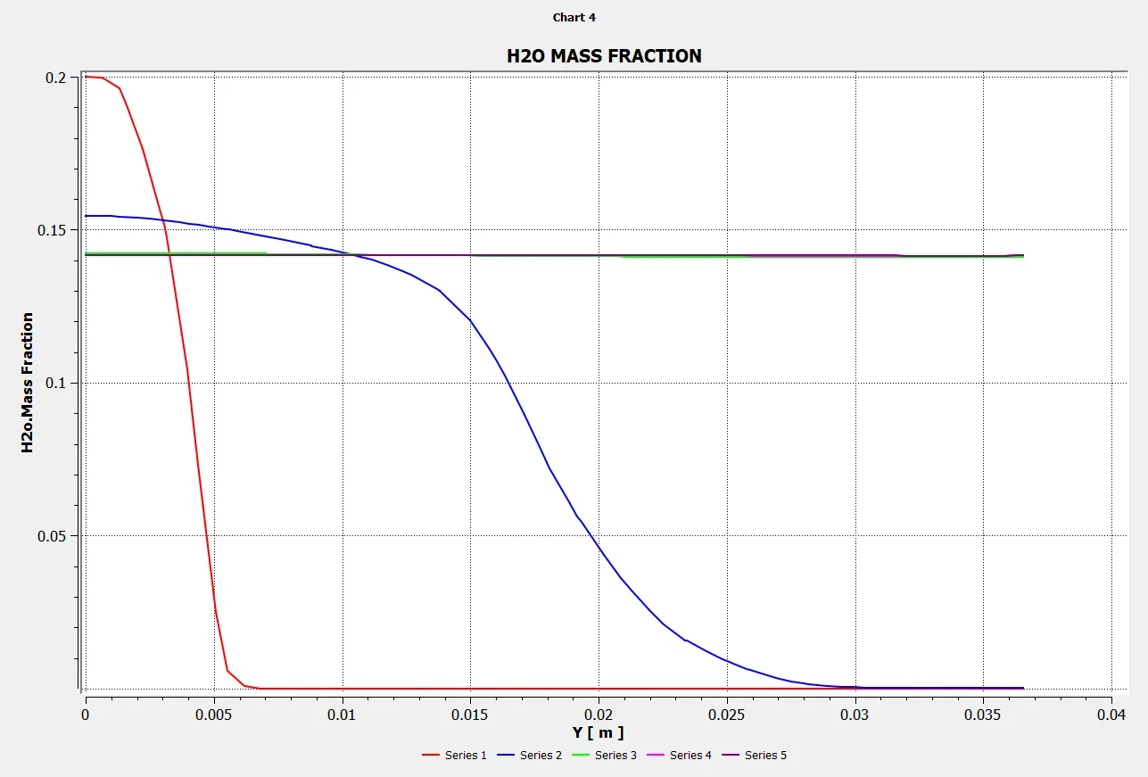
Line probes at different locations:
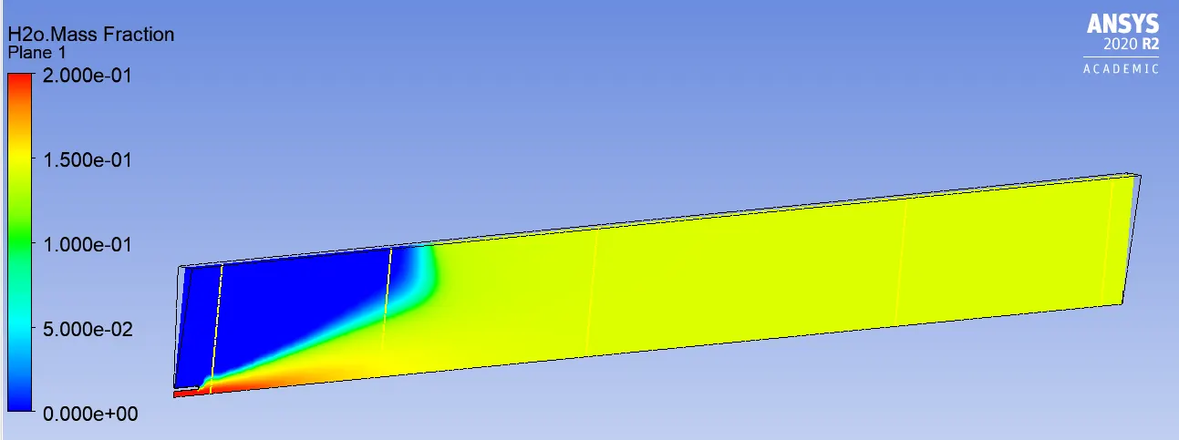
Charts:
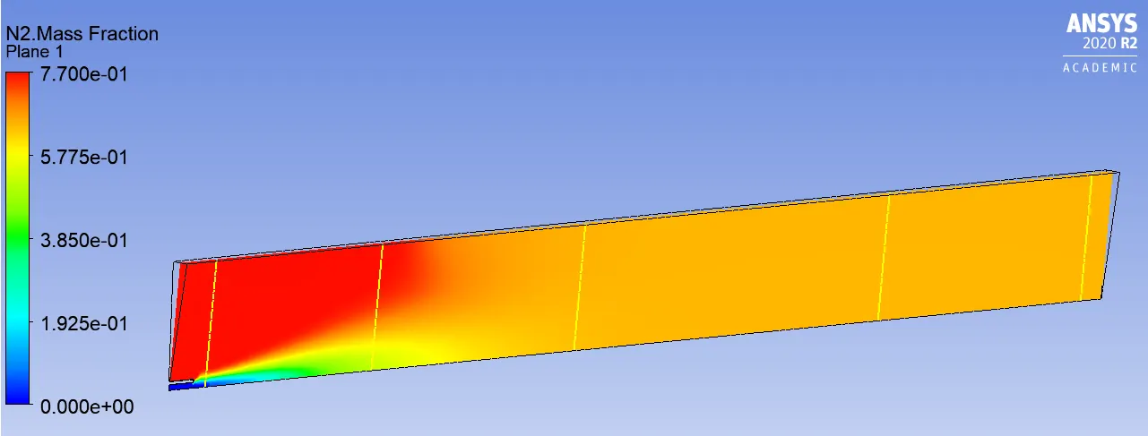
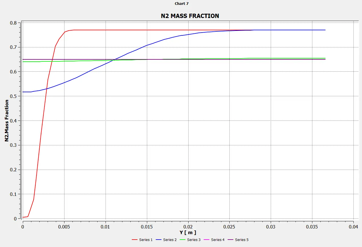
Mass Fraction of N2
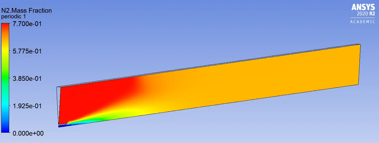
Line probes at different locations:
Charts:
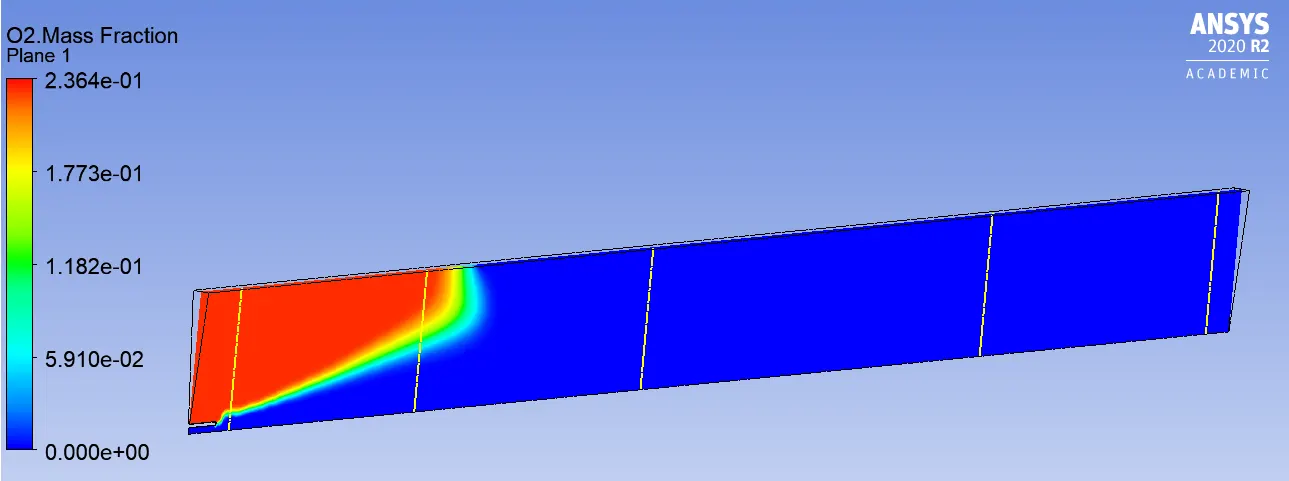
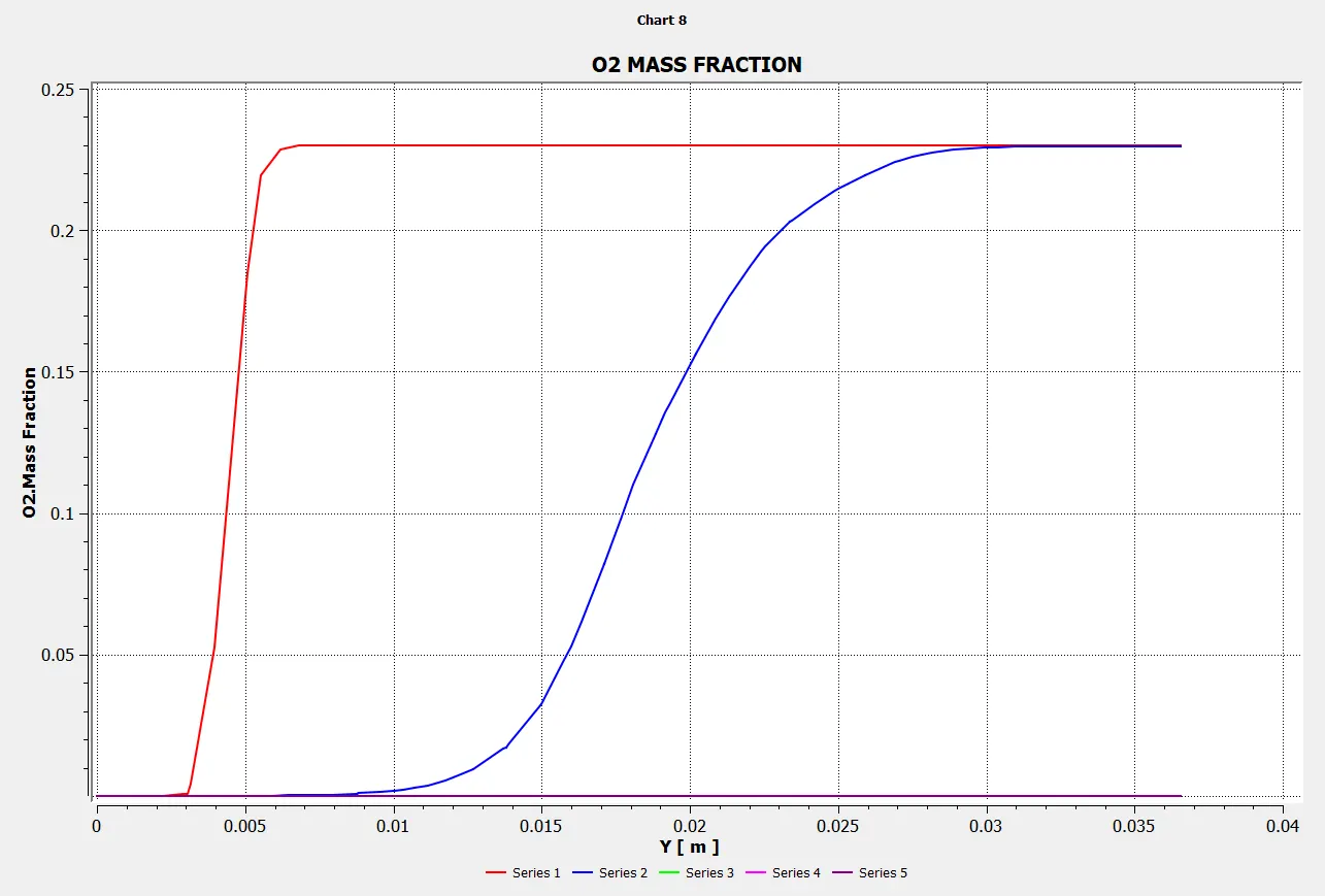
Mass Fraction of O2
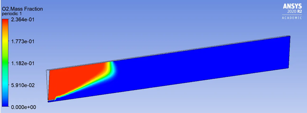
Line probes at different locations:
Charts:
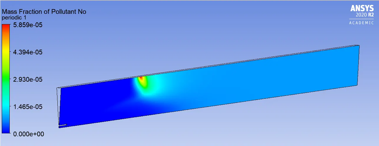
Mass Fraction of NOX
Line probes at different locations:
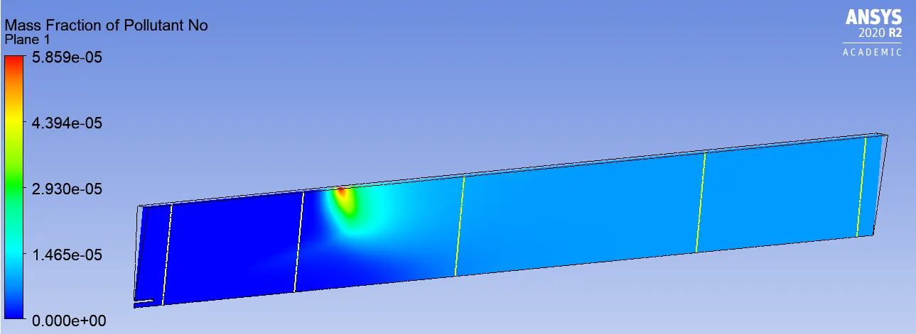
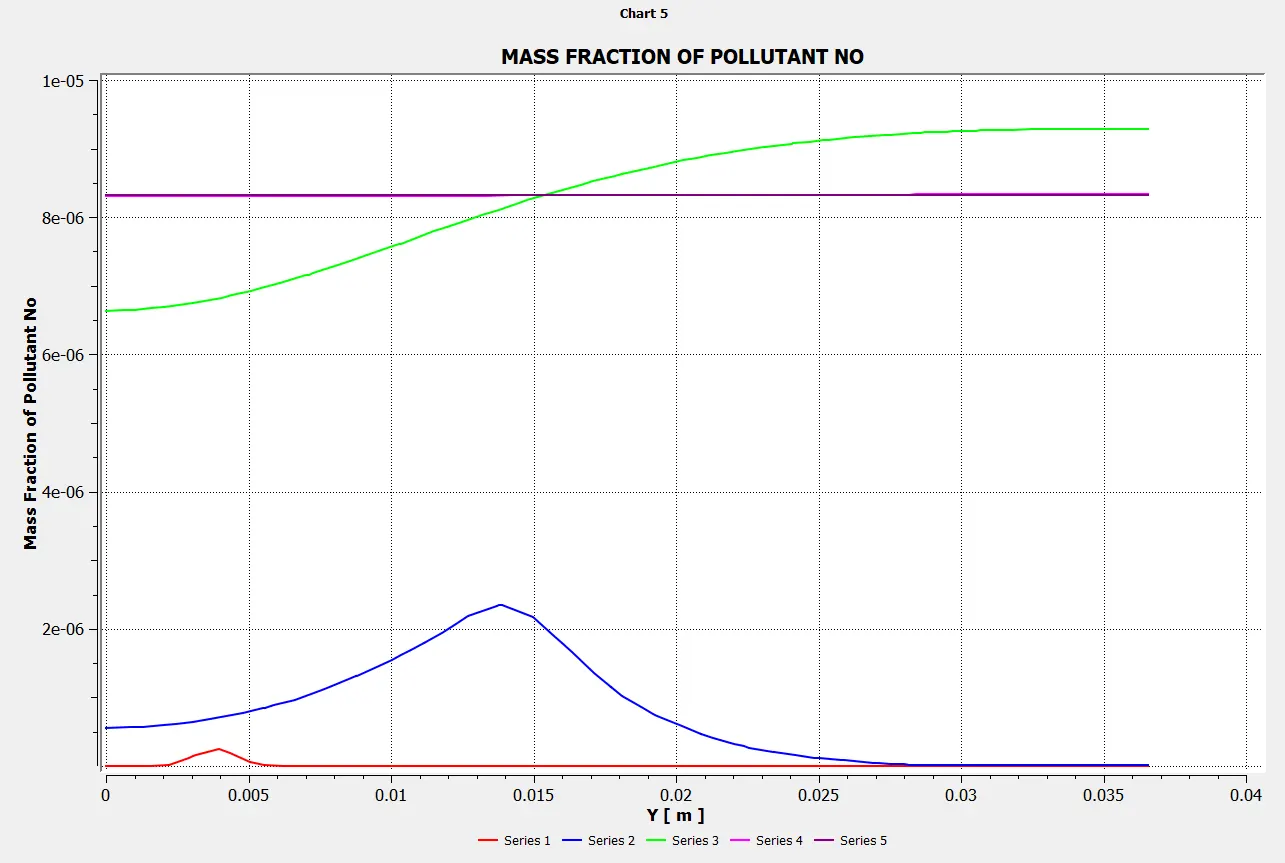
Chart:
Mass Fraction of SOOT
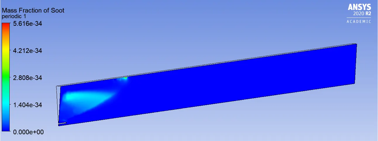
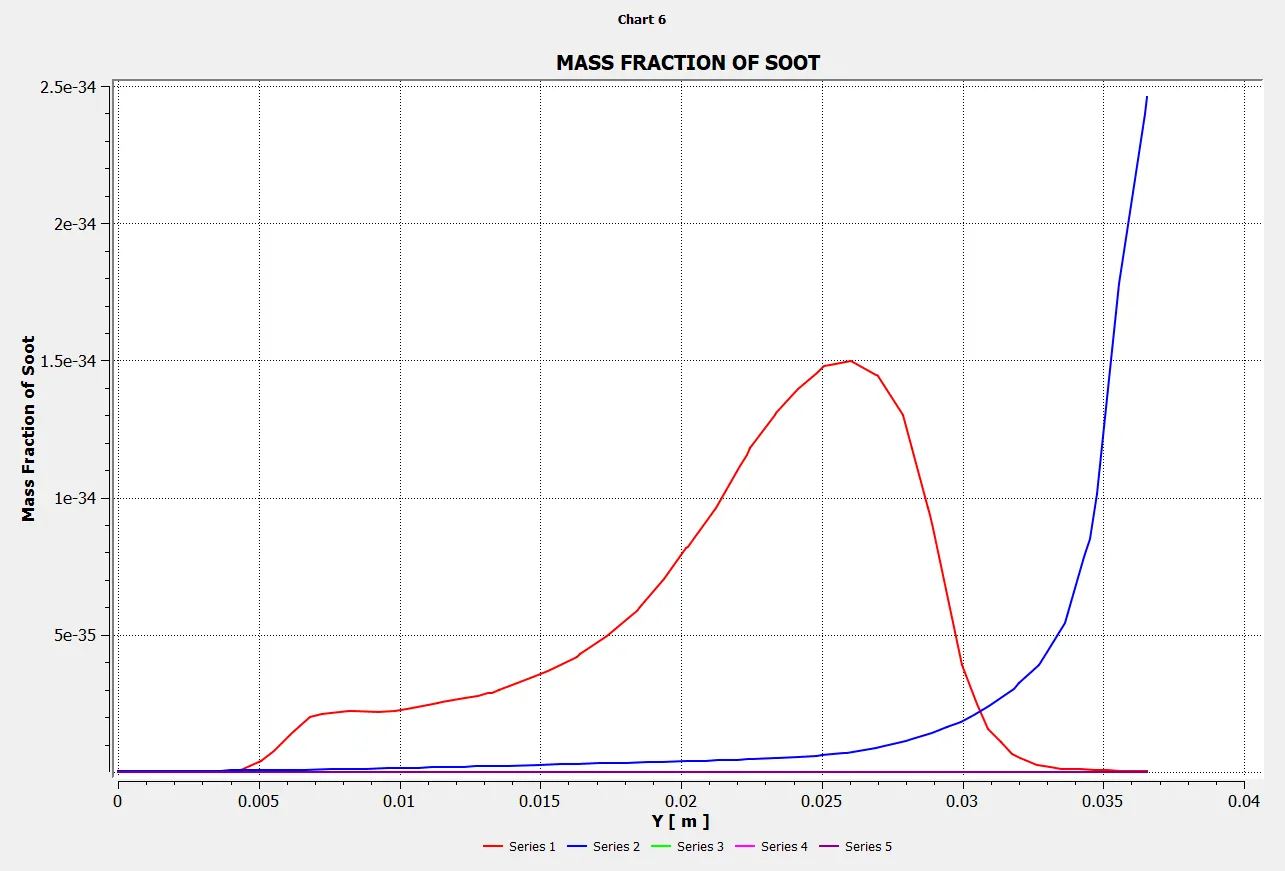
Line probes at different locations:

Chart:
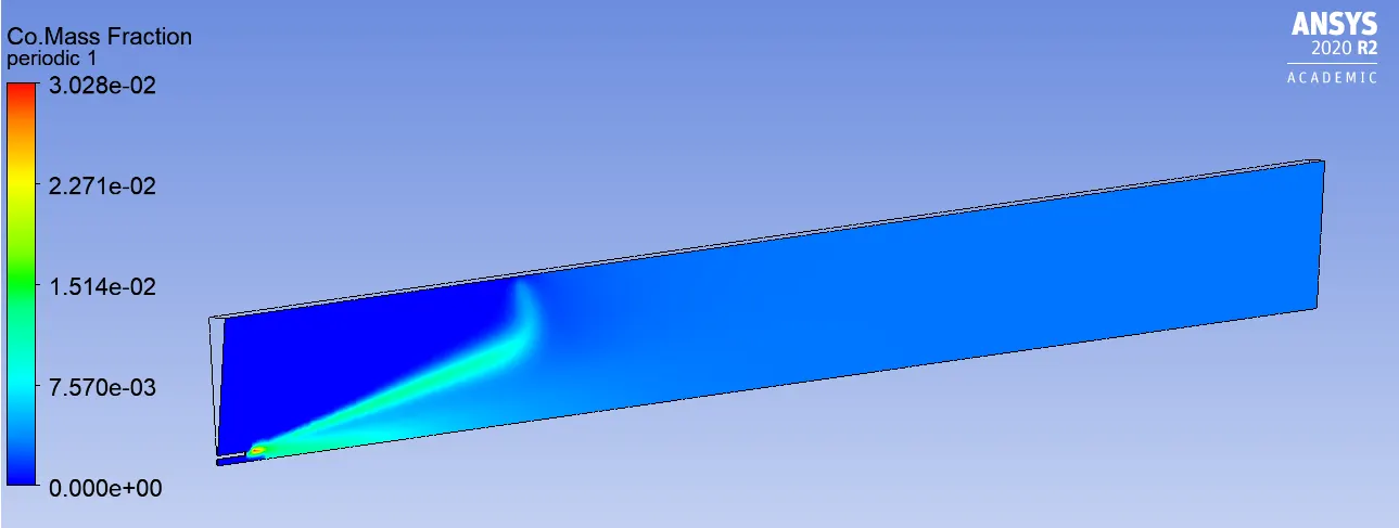
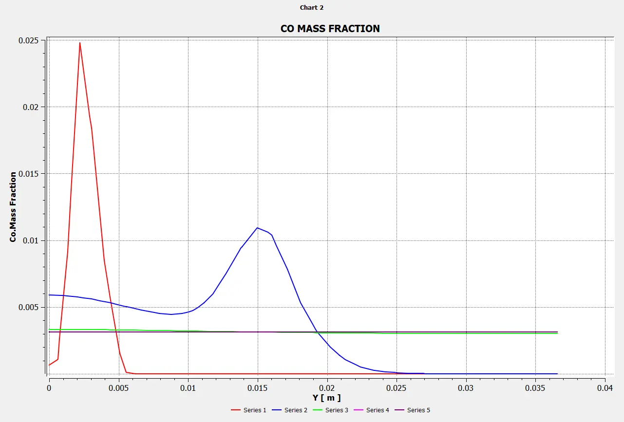
Mass Fraction of CO
Line probes at different locations:
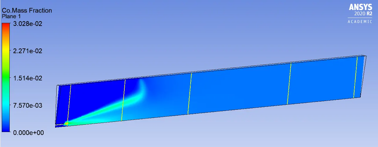
Chart:
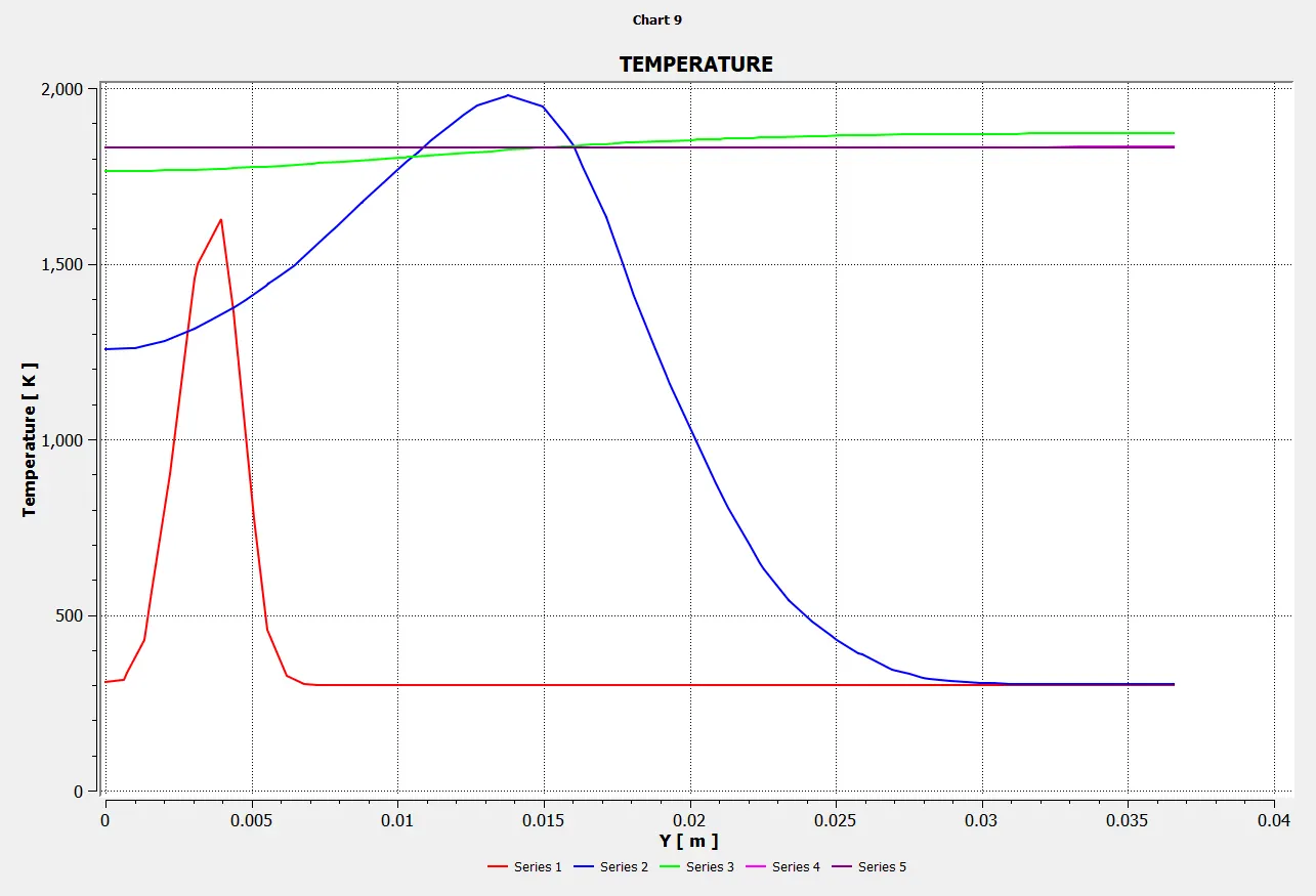
Temperature:
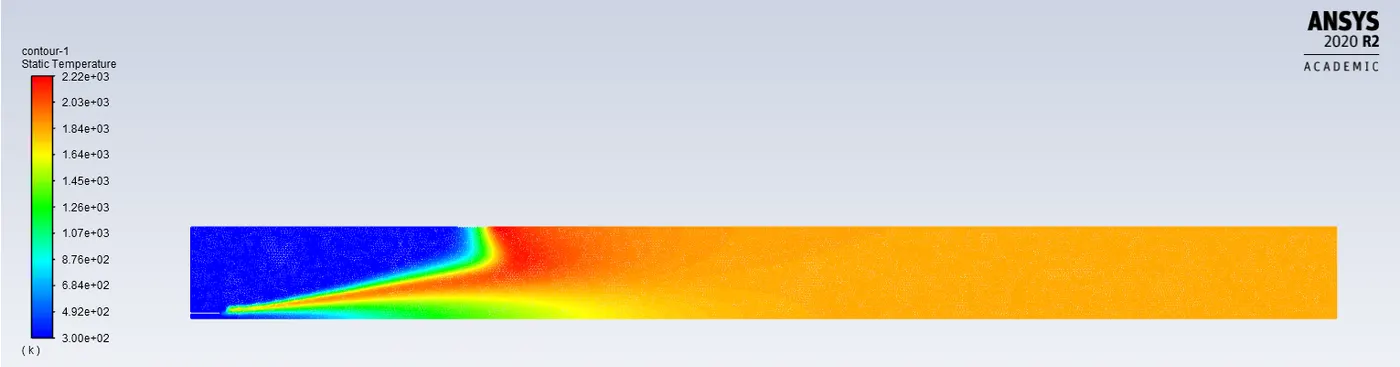
Chart:
Animation:
Case-4: (CH4=0.7 & H2O=0.3)
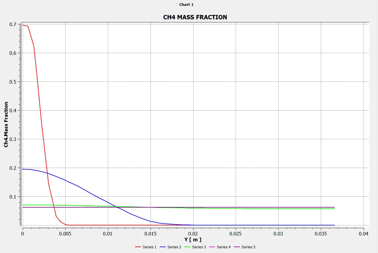
Mass Fraction of CH4
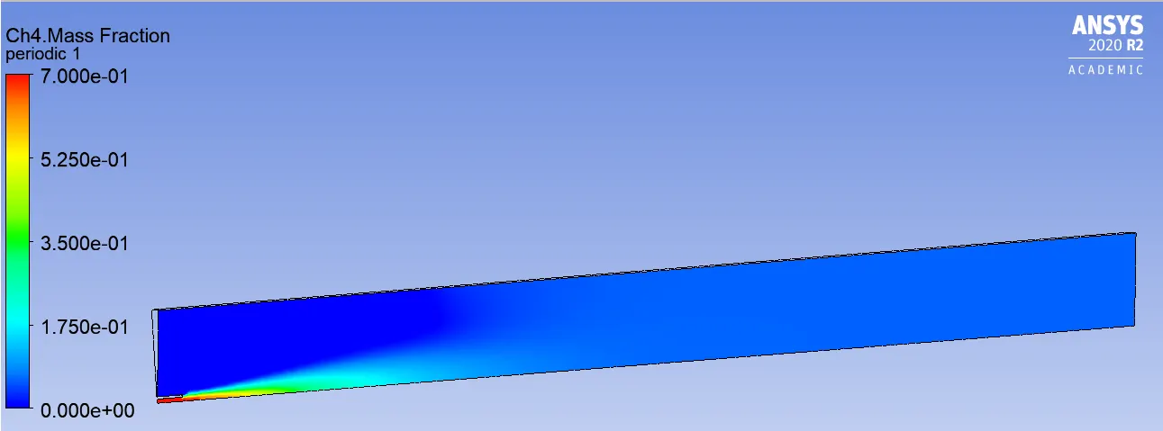
Line probes at different locations:
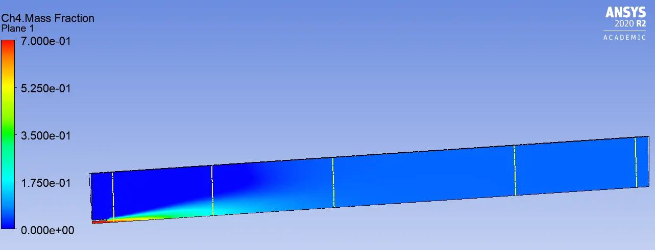
Chart:
Mass Fraction of CO2
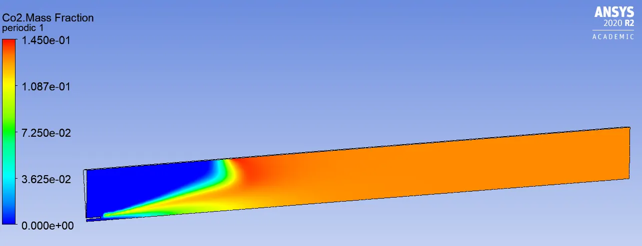
Line probes at different locations:
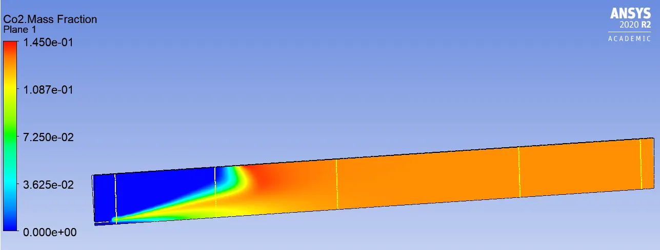
Chart:
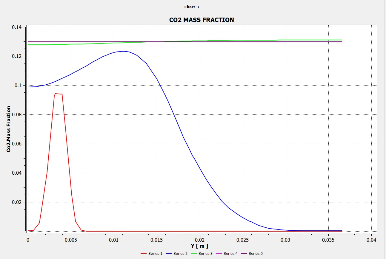
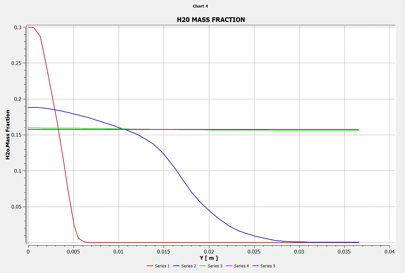
Mass Fraction of H20
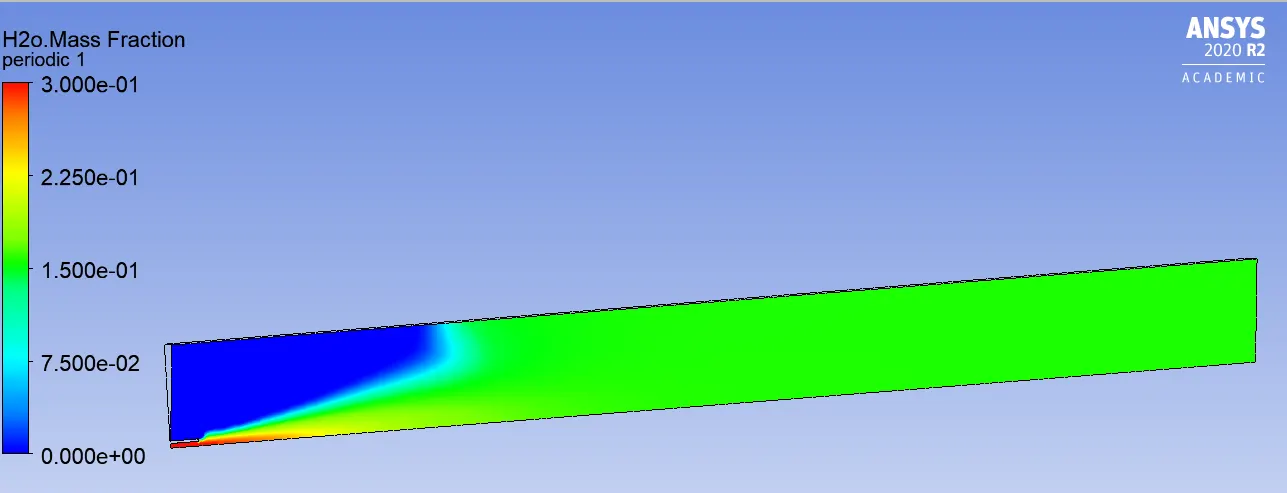
Line probes at different locations:
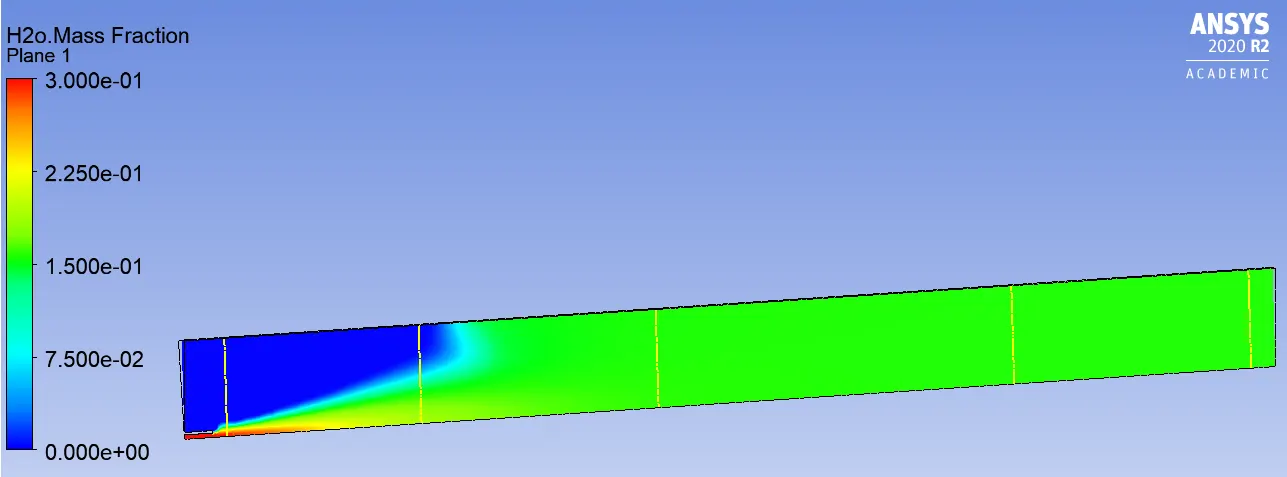
Chart:
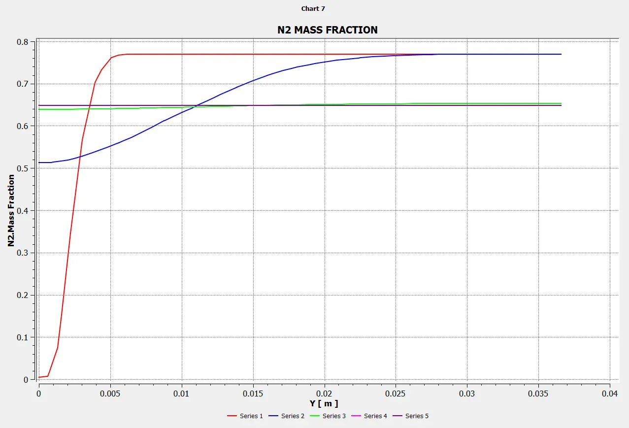
Mass Fraction of N2
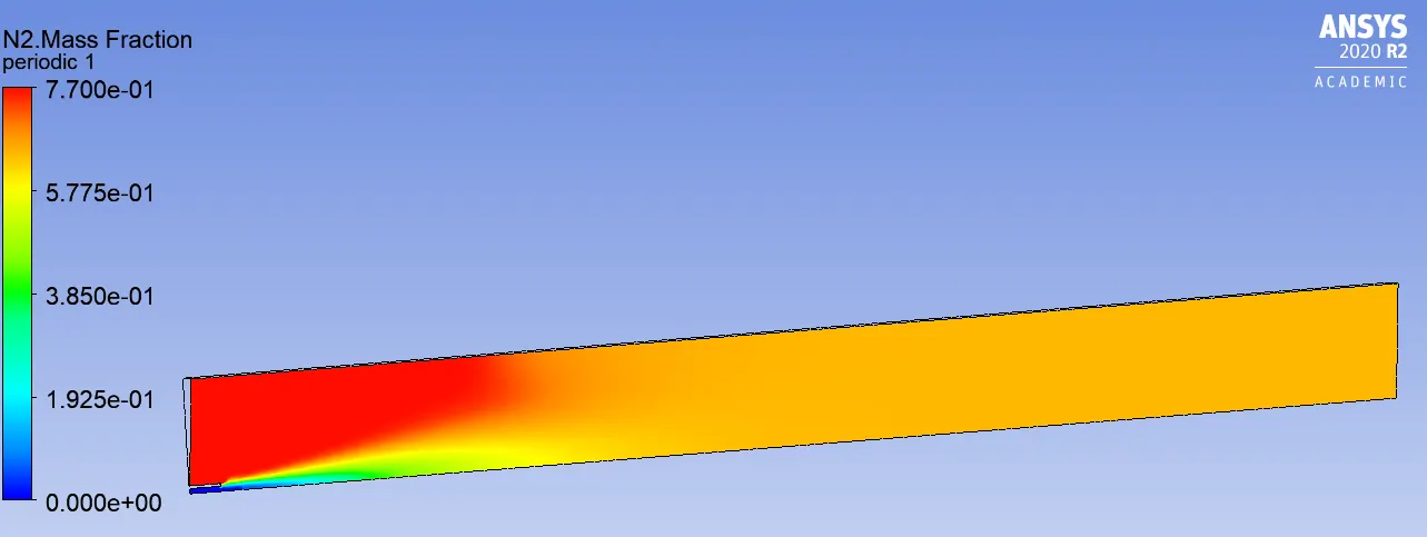
Line probes at different locations:
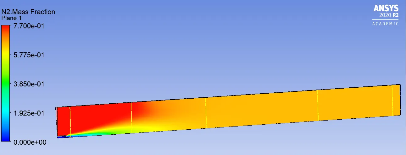
Chart:
Mass Fraction of O2
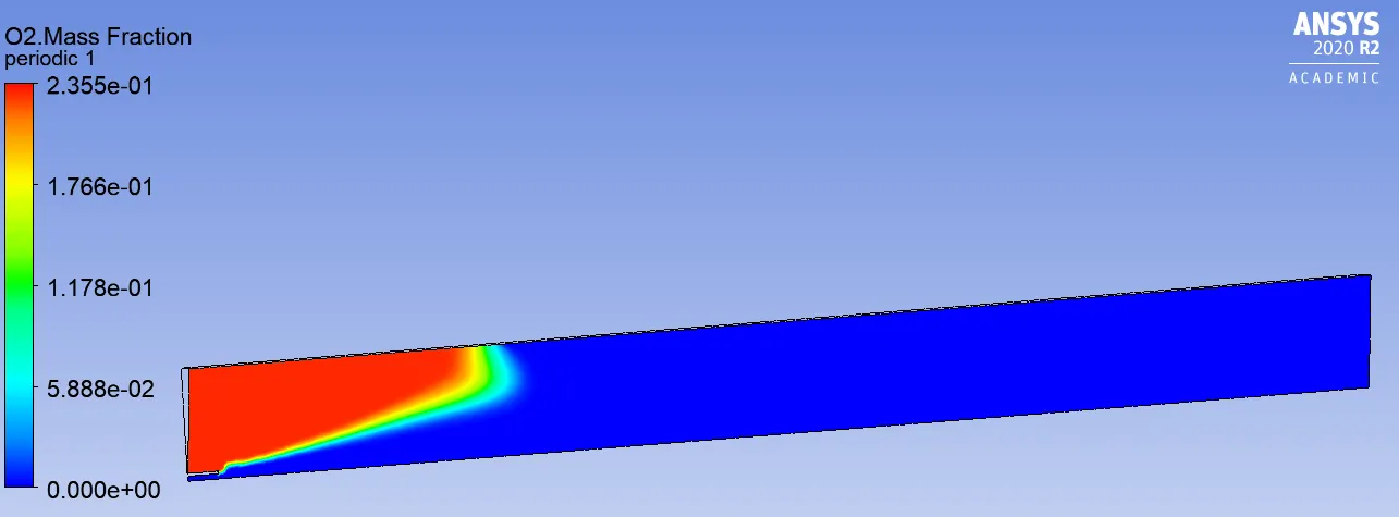
Line probes at different locations:
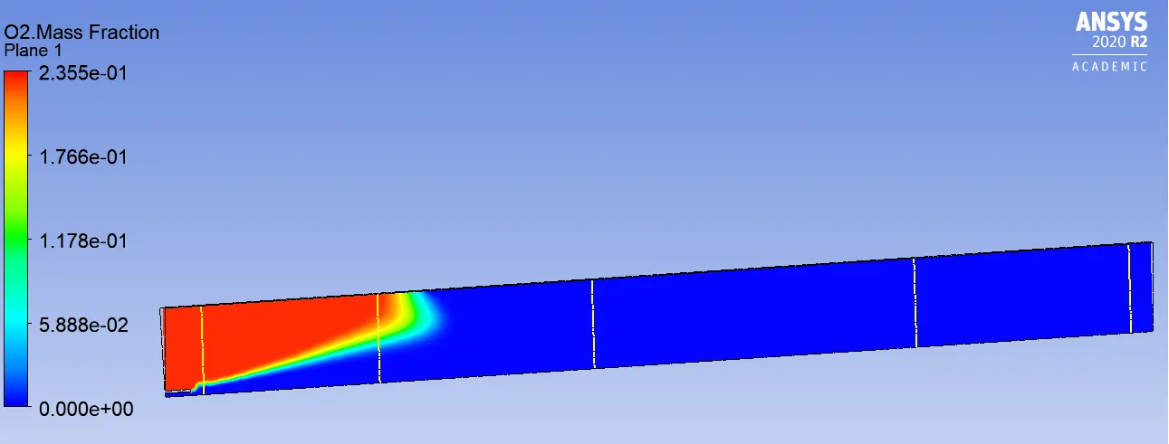
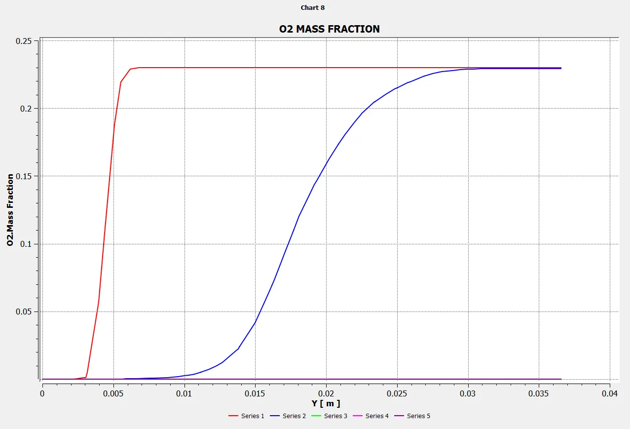
Chart:
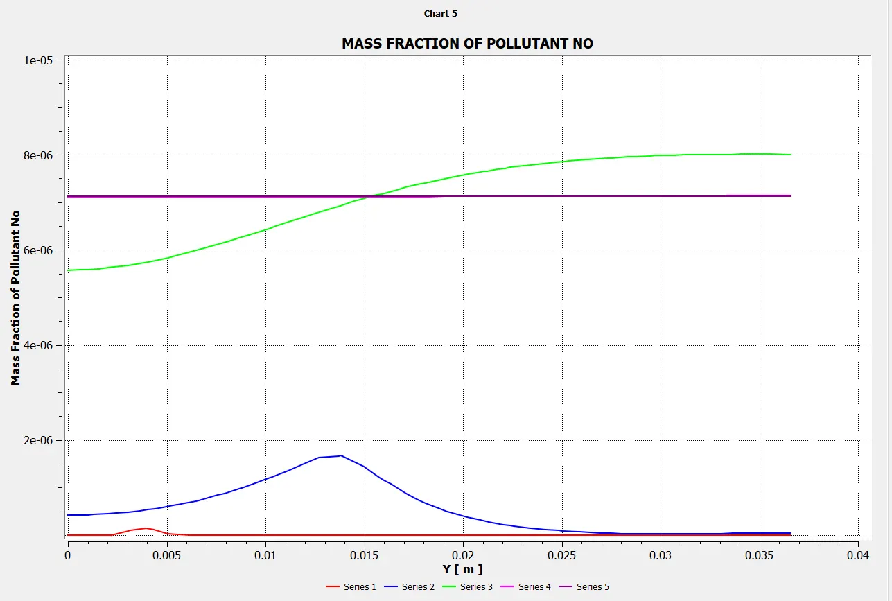
Mass Fraction of NOX
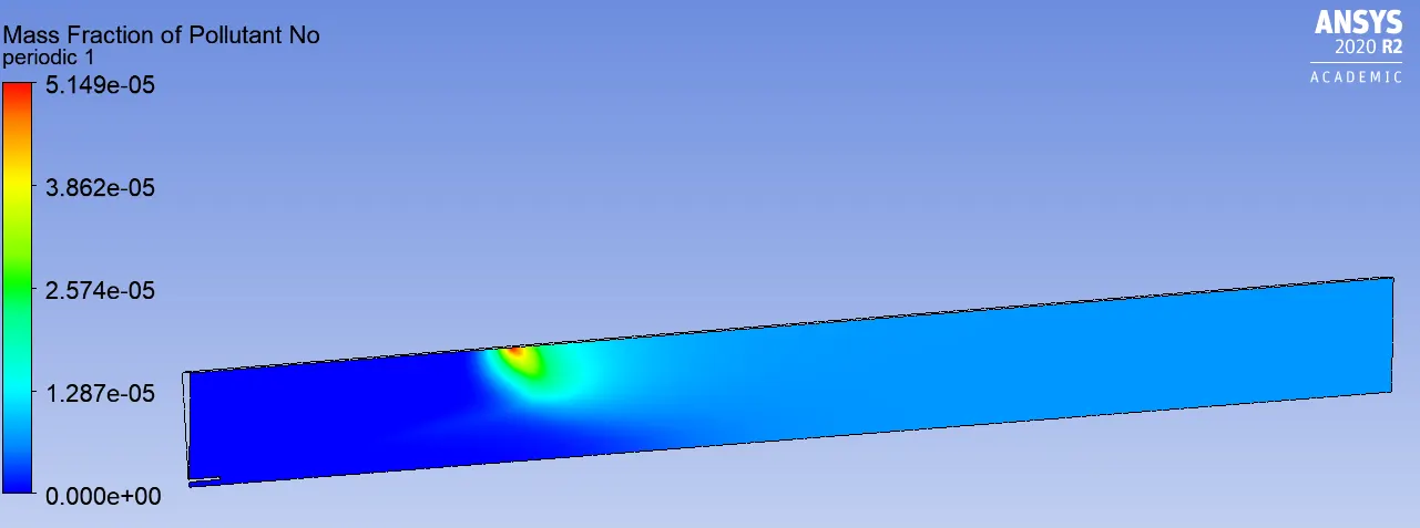
Line probes at different locations:
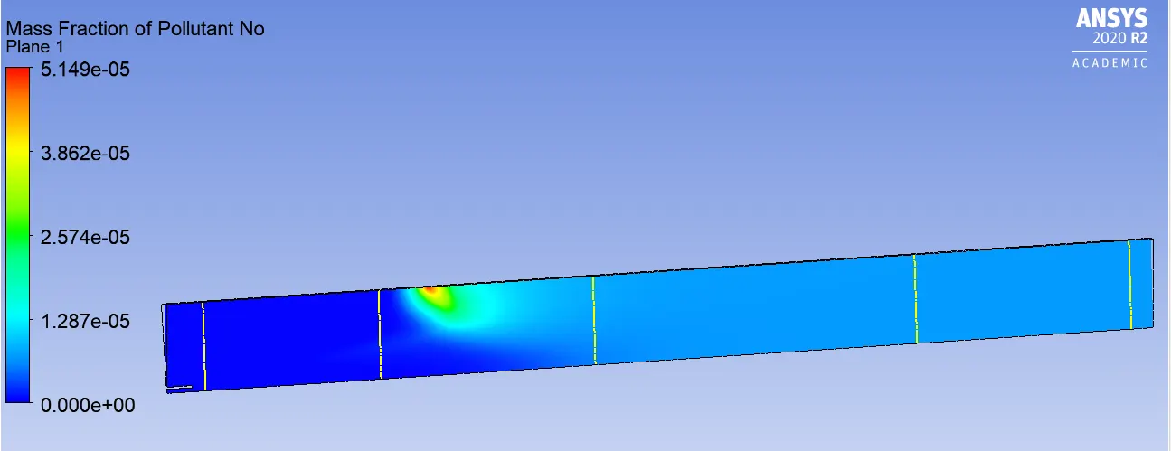
Chart:
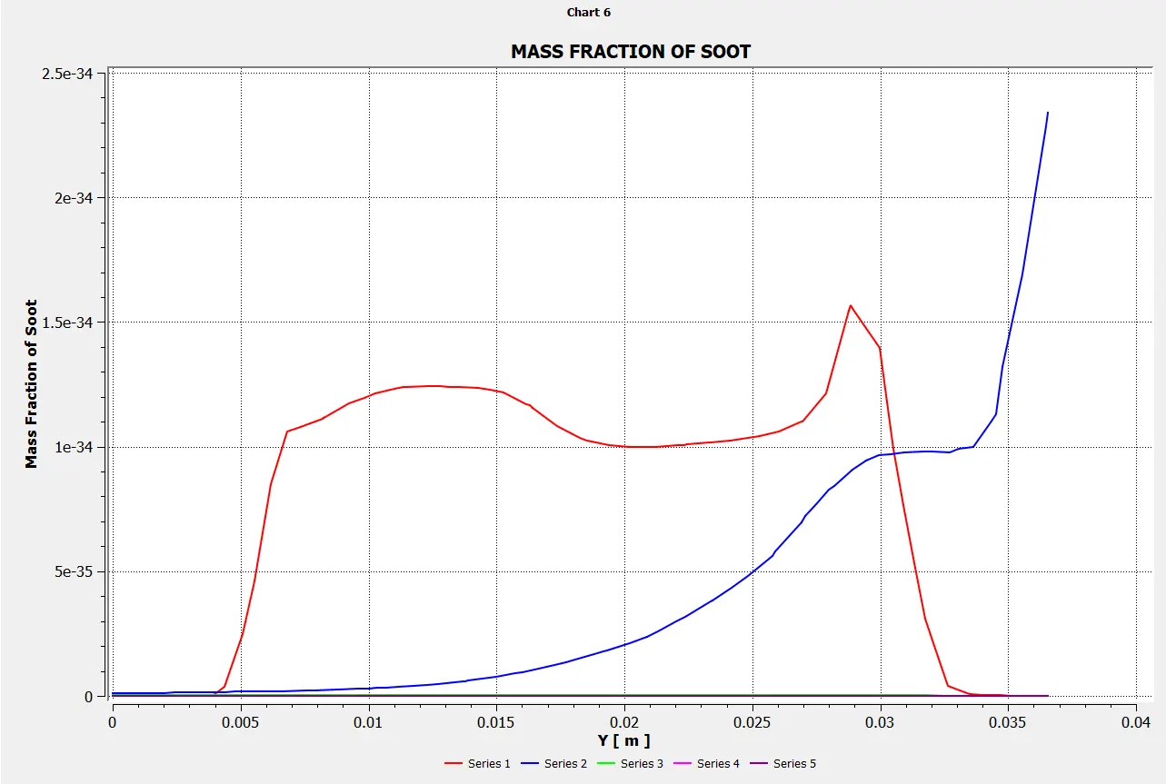
Mass Fraction of SOOT
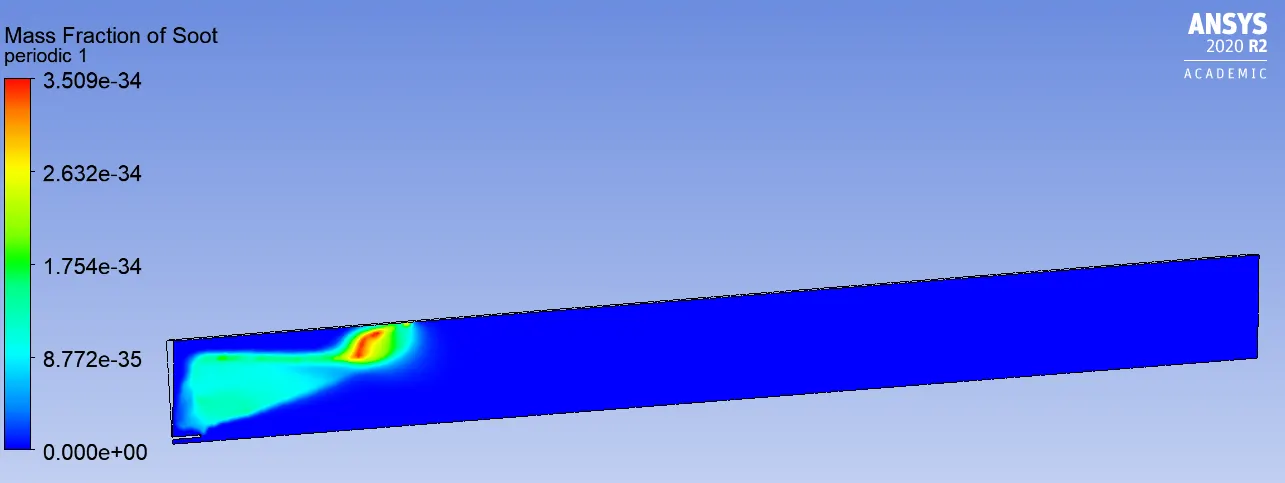
Chart:
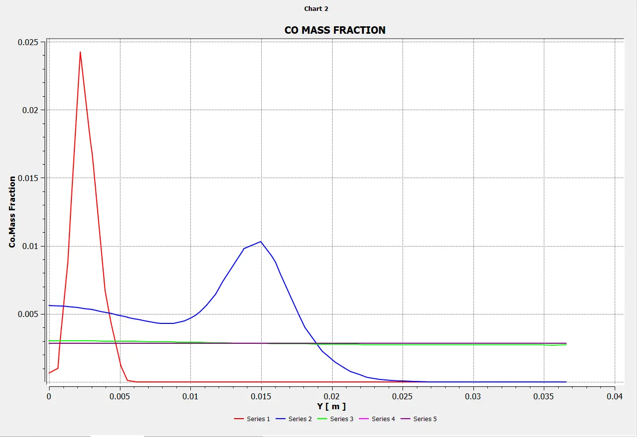
Mass Fraction of CO
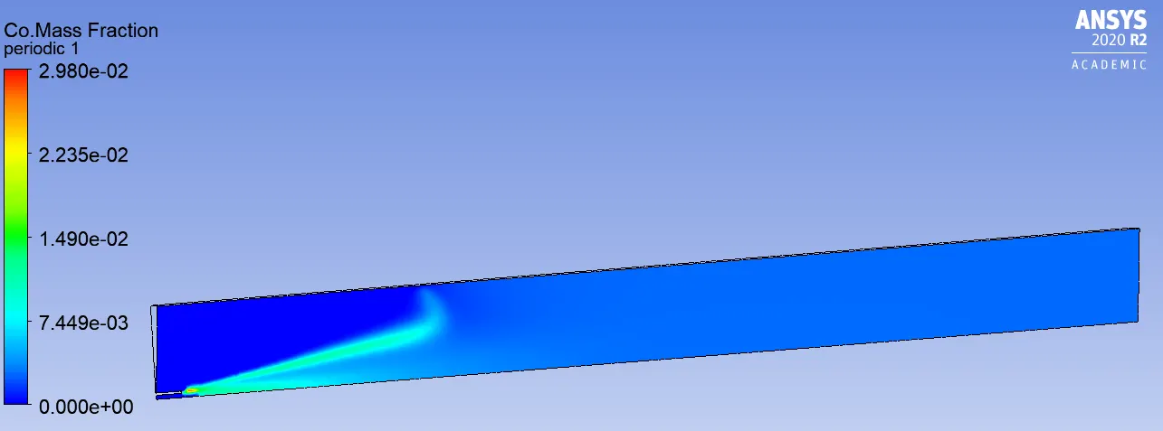
Line probes at different locations:
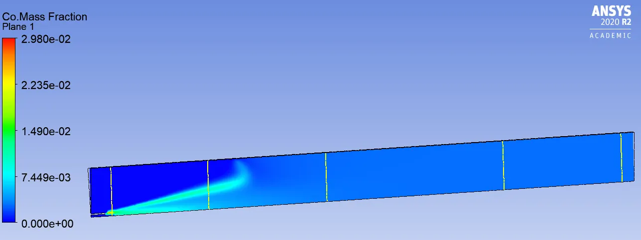
Chart:
Temperature:
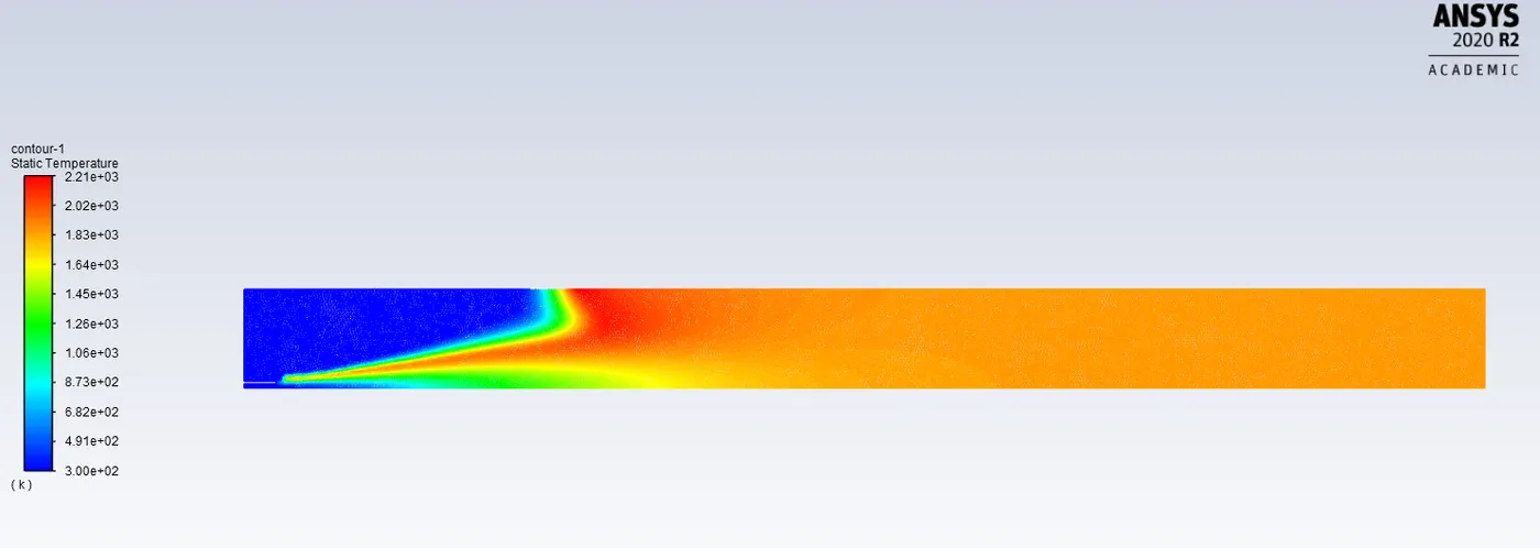
Chart:
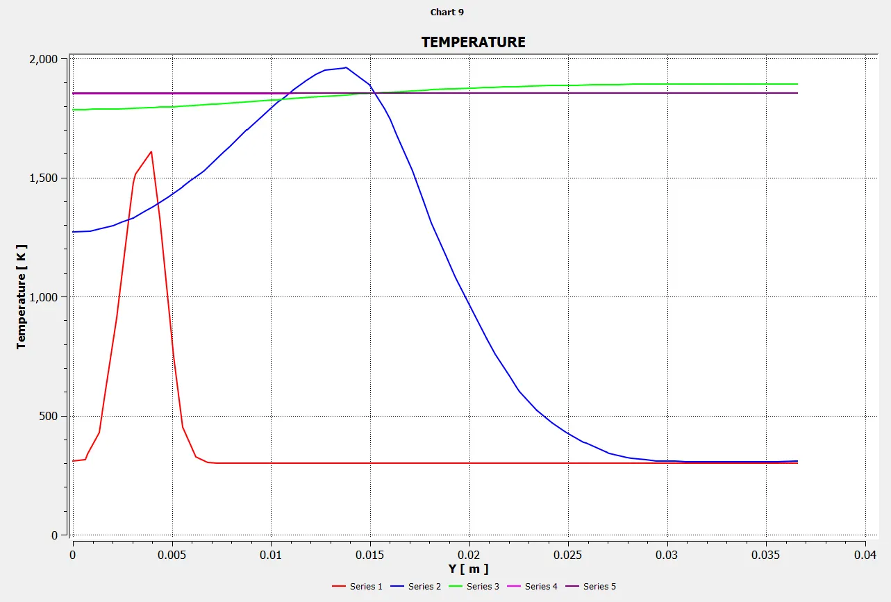
Animation:
RESULTS:
Part-1
Mass Fraction of NOx- 1.07E-05
Mass Fraction of SOOT- 8.75E-36
Part-2
Adding Water content in the fuel from 5% to 30%.
| S.No | CH4(Fuel Inlet) Mole Fraction |
H2O(Fuel Inlet) Mole Fraction |
MASS FRACTION OF No (NOX) | MASS FRACTION OF SOOT |
| 1 | 0.95 | 0.05 | 8.00E-06 | 6.39E-36 |
| 2 | 0.9 | 0.1 | 7.55E-06 | 4.34E-36 |
|
3 |
0.8 | 0.2 | 6.73E-06 | 7.74E-36 |
|
4 |
0.7 | 0.3 | 5.77E-06 | 1.42E-35 |
Effect on formation of NO by injecting H2O in the fuel from 0-30%
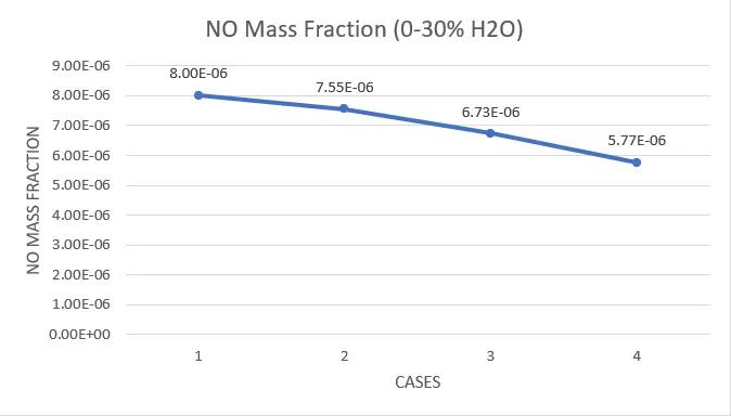
- In the initial case i.e. when we used material=methane-air, it is observed that Nox and soot are formed at the outletof the combustor. In order to minimise the formation of NOx and SOOT, water(H2O) is added to the fuel.
- From the above test cases it is concluded that increasing the ratio of water showed the reduction of NOx and SOOT formation, but there is no much effect on N2 and O2.
- O2 reduces due to the formation of N2O and other products. As the temperature increases continously with the increase of water content that means more amount of oxygen is utilised for combustionof the fuel.
- The combustion process doesnot need any external ignition source to initate the combustion. The eddy dissipation model, the fuels are fast burning and the entire reaction rate is monitored by the turbulence mixing.
- Here the combustion takes place whenever there is a turbulence present in the flow.
CONCLUSION:
The combustion simulation on the combustor model is performed by representing the mass fraction of various species at various locations. In order to minimize the amount of NOx and soot, some amount of water is added in the fuel and various effects are recorded during the simulation. Hence its concluded that, on adding water content to the fuel NOX and SOOT reduced gradually and resulted in good combustion.