Challenge on Combustion
OBJECTIVE
The objective is to perform a combustion simulation of air and fuel mixture and to study the effect of water content on Nox and soot.
ASSUMPTIONS
The combustion cylinder is considered to be axi-symmetric and therefore its 2d profile is meshed for the combustion simulation.
TYPES OF COMBUSTION
1. Diffusion or Non-Premixed Combustion
• Separate streams for fuel and oxidizer.
• Convection or diffusion of reactants from either side into a flame sheet. eg: Simulation of Diesel engines and pulverized coal burners.
2. Premixed combustion
• Fuel and oxidizer are already mixed at the molecular level before ignition.
• Diffusion heat and radicals from the products to the reactants.
• The rate of propagation (flame speed) depends on the internal flame structure. eg: Simulation of Petrol engines
3. Partially Premixed Combustion
• Reacting systems with both non-premixed and premixed fuel/oxidizer streams (i.e) intermediary representation of premixed & non-premixed combustion model.
Turbulence-Chemistry Interaction
It indicates which model is to be used for turbulence-chemistry interaction when the species transport model with volumetric reactions is used.
1. Finite-Rate/No TCI
The Finite rate model is used to compute only the Arrhenius rate & neglect the turbulent-chemistry interaction.
2. Finite-Rate
It is used for turbulent flows computes both the Arrhenius rate and the turbulence-chemistry interaction and uses the smaller of the two.
3. Eddy-Dissipation
It is used for turbulent flows computes only the mixing rate when air & fuel mixes & combustion starts after x seconds where the value of x is obtained from the k-e model. So the ignition source is not required.
ACTION
Workflow for an Ansys Fluent
1. Pre-processing(preparing the 2D geometry and discretize the geometry).
2. Setting up Solver (Setting up the physics & solution).
3. Post-processing.
Pre-processing
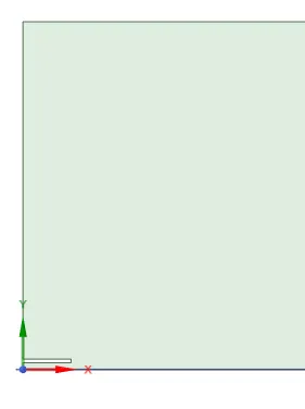
The 2d cross section of combustion chamber is used for simulation.
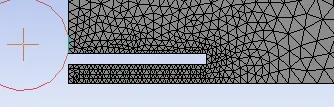
A triangular mesh is used with 4mm mesh size.
Nodes-5351
Elements-10165
Inlet,outlet,walls and symmetry boundaries will be defined.
The Name selection of model are:-
Fuel inlet
Air inlet
Axis
Wall
Outlet


Solver characteristics
Setting up Physics
- Solver - Pressure based type, steady-state, Absolute velocity & 2D plane axisymmetric to solve the 2D model.
Viscous model - k-epsilon, Standard model & standard wall functions
Step11: setup the boundary condition as per the given data.
Solver: steady-state, pressure-based, absolute, and axisymmetry.
Viscous model: K-epsilon, standard, standard wall treatment.
Zones: air-inlet-velocity inlet-0.5m/s
species-O2-0.23
fuel-inlet-velocity inlet- 80m/s
species-CH4-1
NOx model -on
soot model>one step -on
NOx Model
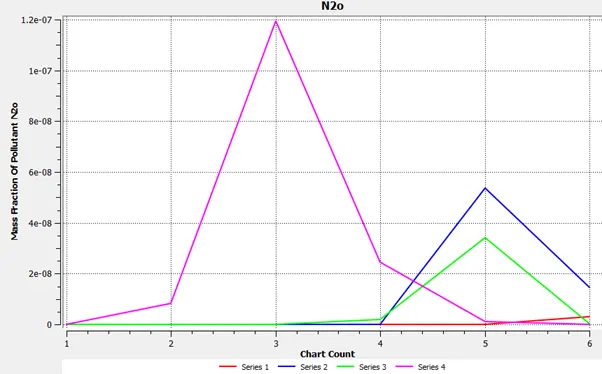
Mainly consists of Nitric oxide (NO), Nitrogen peroxide (NO2) and Nitrous oxide (N2O) to a smaller extent
Thermal, Prompt, Fuel and N2O intermediate mechanisms are available.
Thermal NOx - It is formed when nitrogen and oxygen in the combustion air combine with one another at the high temperatures in a flame.
Prompt NOx - Forms from the rapid reaction of atmospheric nitrogen with hydrocarbon radicals.
Fuel NOx - It is formed by the reaction of nitrogen bound in the fuel with oxygen in the combustion air. It is rarely a problem with gaseous fuels.
all function.
Soot Model
Formed in fuel-rich zones with strong temperature gradients.
Complex nucleation, surface growth, coalescence, aggregation phenomenon can be included
One-step Khan & Greeves model, Two-step Tesner model, Moss-Brookes model and MossBrookes-Hall model are available.
Materials - The fuel material for combustion is Methane-air.
Species
- Boundary Conditions: Velocity inlets - Air inlet - 0.5m/s, Mass fraction O2 - 0.23. Fuel Inlet - 80m/s, Mass fraction CH4 - 1. water fraction is set to be 0 for the baseline scenario. Pressure outlet - Gauge pressure is set to 0.
- Setting up solver - Hybrid solver has used & contours for the Temperature, NOx, Soot is created.
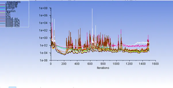
The simulation is made to run for 1500 iterations and the following graphs is obtained for Residuals.
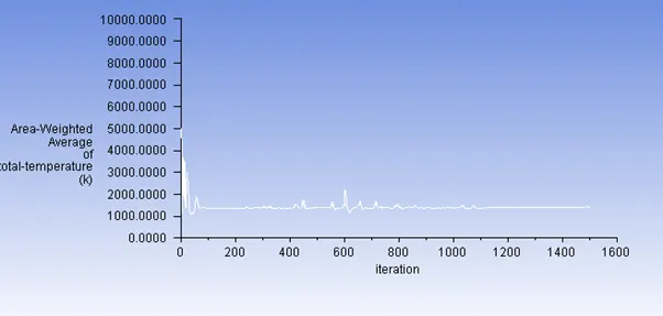
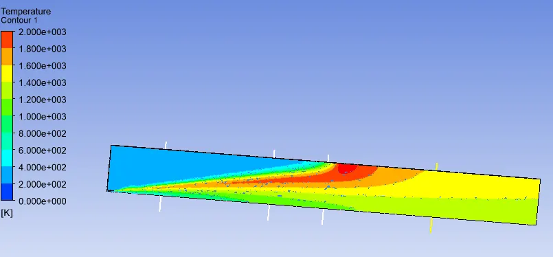
The area averaged temeperature at the outlet was obtained as follows-
Post-processing
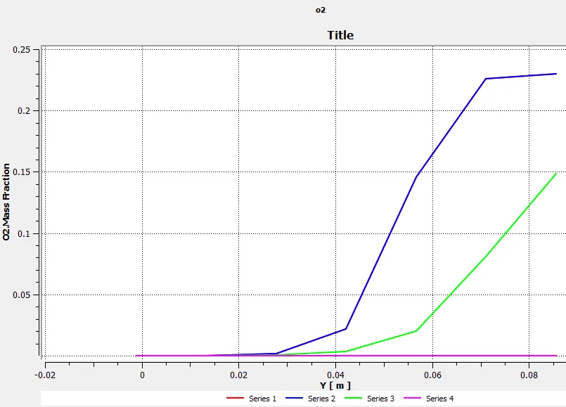
- Plot the variation of the mass fraction of the different species in the simulation using line probes at different locations of the combustor.
- Create a chart from the line probes for CO2, H2O, CH4, N2, O2, NOx emissions & Soot formation.
Line Probes
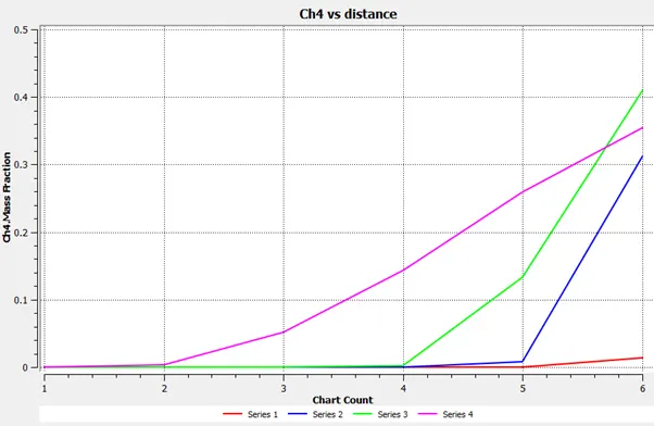
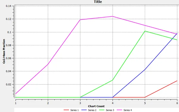
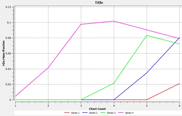
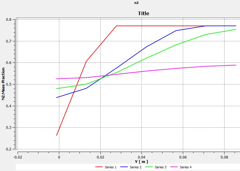
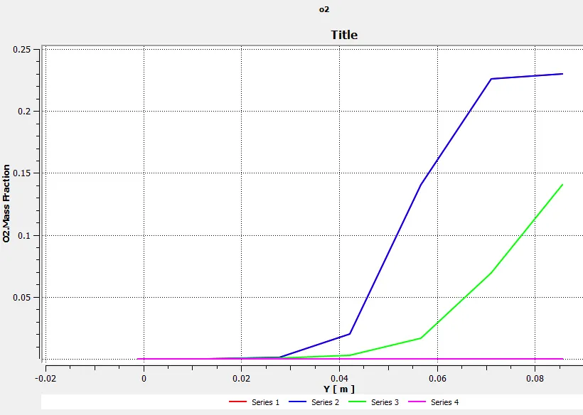
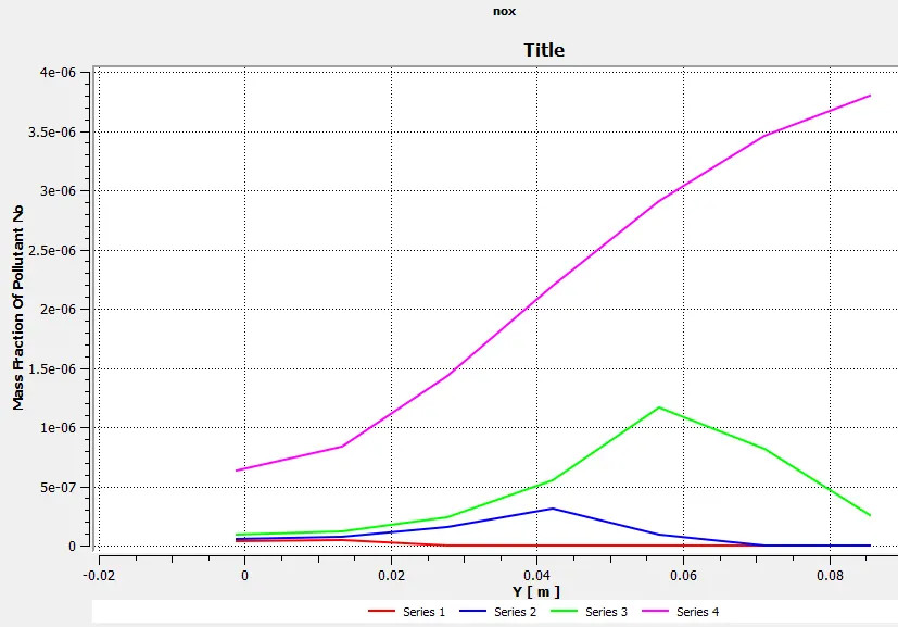
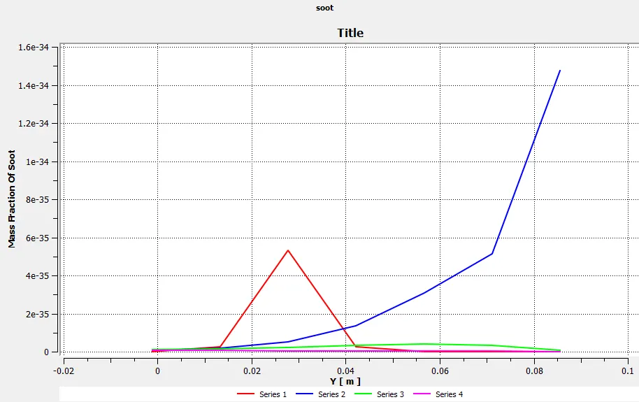
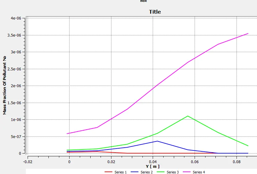
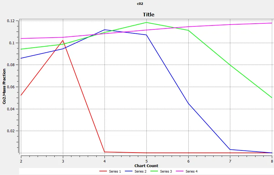
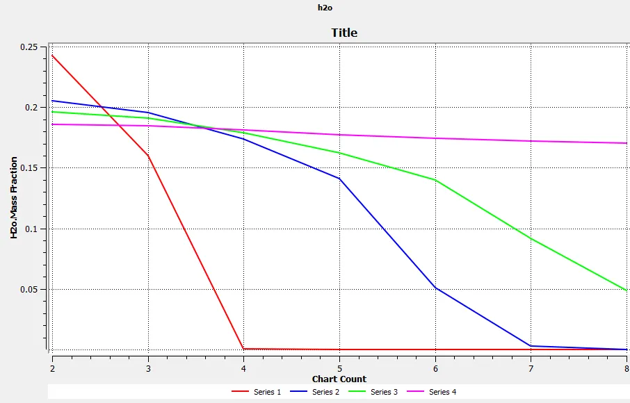
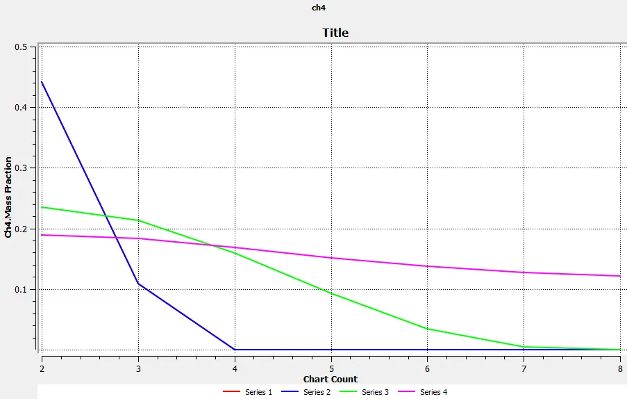
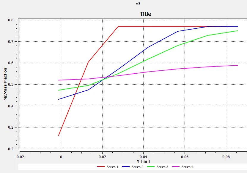
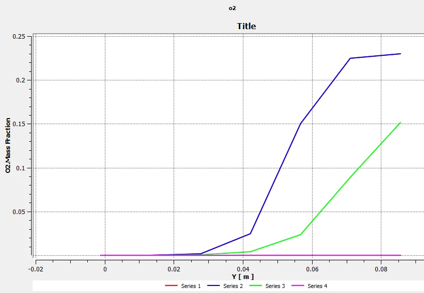
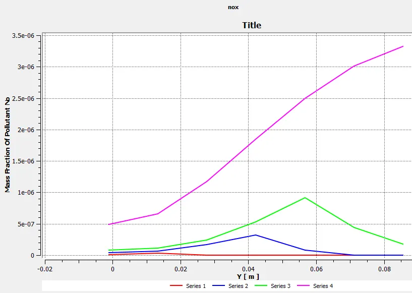
The lines are set up 0.1,0.3,0.4 and 0.6 m from the origin,which lies on the fuel inlet side of the cross section.
And the names "Series1","Series2","Series3","Series4" correspond to the respective distances.
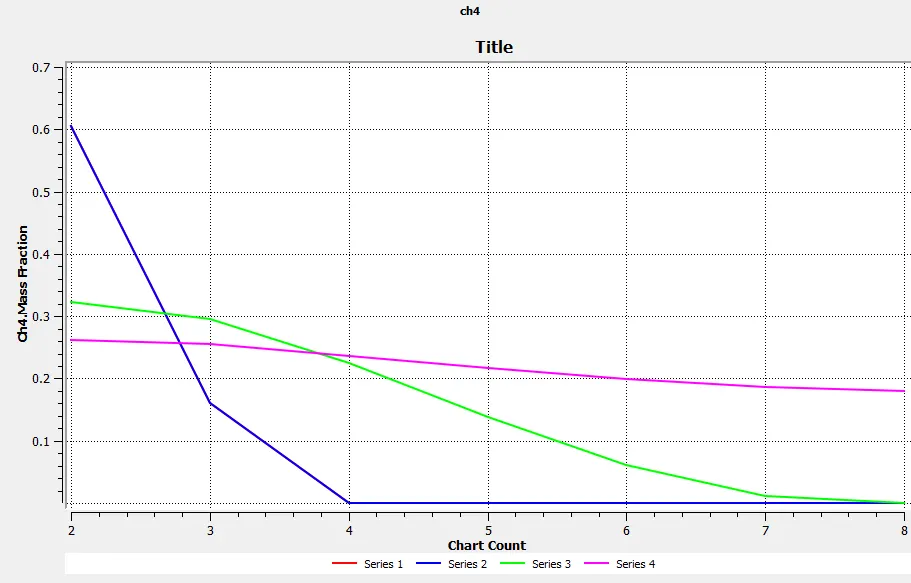
CH4 Plot
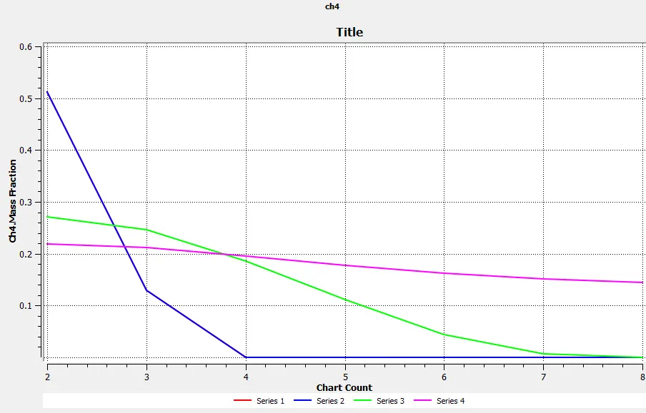
The CH4 mole fraction is high at the inlet of fuel & reduces along the flow also becomes zero after the combustion starts. This is mainly because of the non-predictive model where combustion depends on k & e values so the parameters during combustion is not captured properly.
CO2 Plot
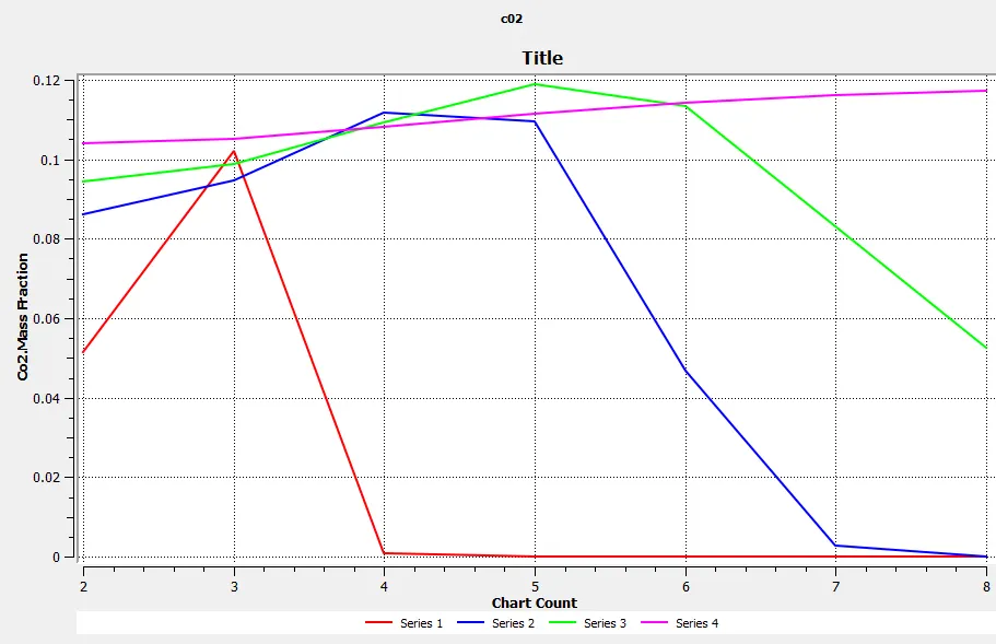
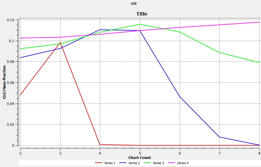
From the chemical reaction between methane & air products such as H2O, CO2 & N2 are mainly produced. So the mass concentration of CO2 is high after the combustion which gets reduces at the outlet.
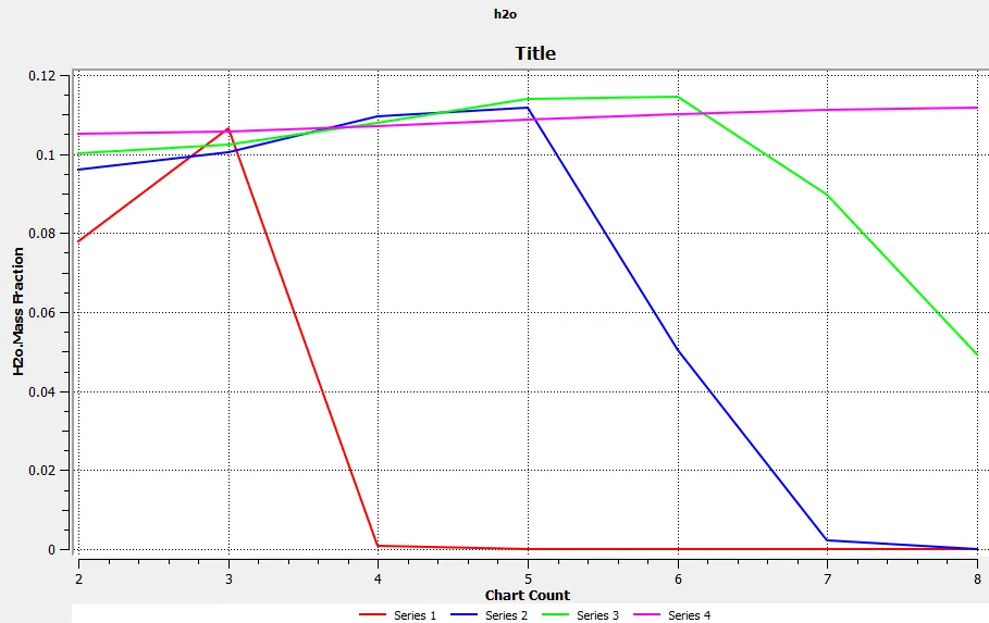
H20 Plot
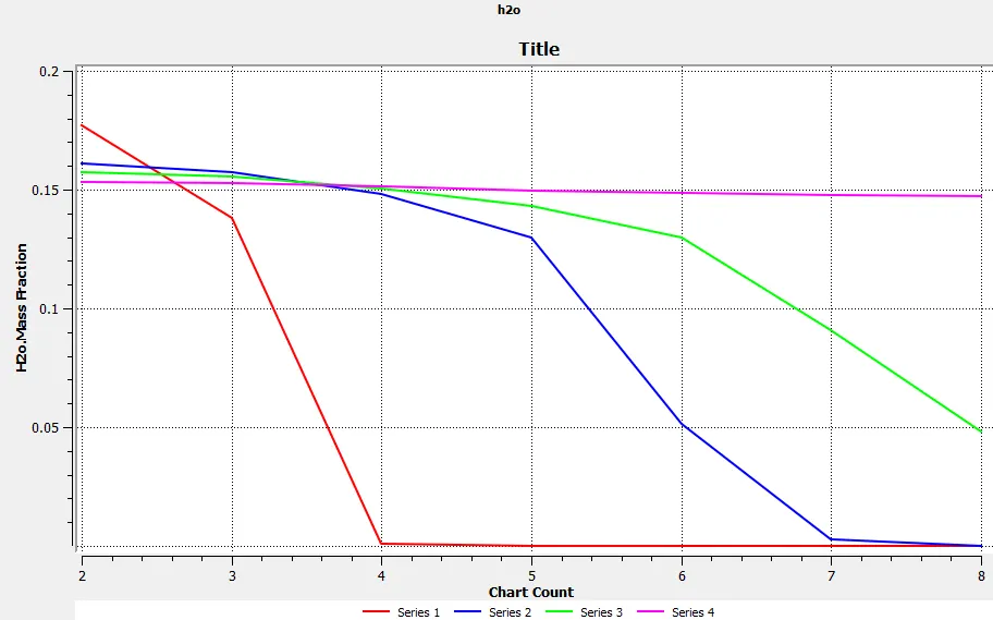
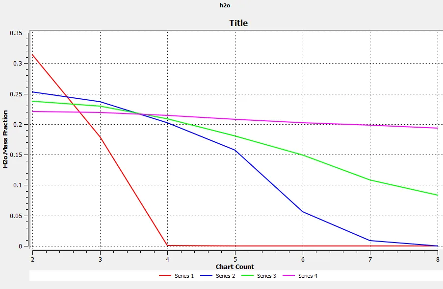
The H2O is also a product of the combustion so the similar plot for CO2 is produced.
N2 Plot
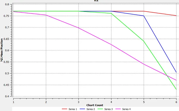
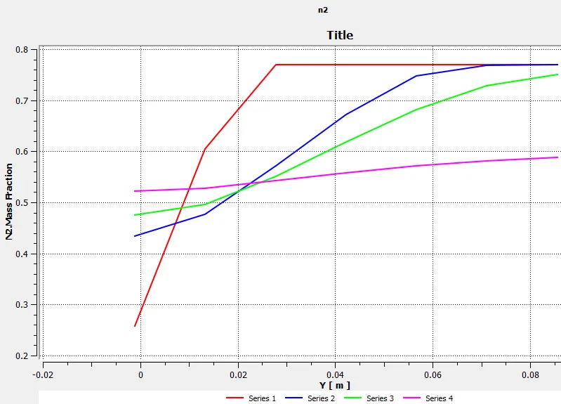
The nitrogen is the main constituent in the air so the amount of N2 is almost the same throughout the combustion & at very high temperature during combustion N2 mixes with O2 to produce oxides of nitrogen. Since the fuel has a separate valve so the N2 concentration are very low.
O2 Plot
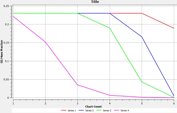
The O2 is a basic component which is used for the combustion so the amount of O2 is less during the combustion since the O2 is used by methane to forms the products.
NOx emissions
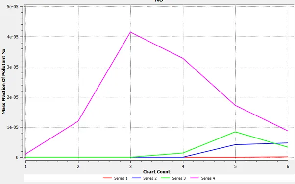
The NOx emissions are produced when the high temperature (around 1500k) is present at the combustion during which N2 mixes with excess O2 produces NOx. From the total temperature plot, it is clear that the temperature was well above 1500k which is depicted by a peak in the NOx plot.
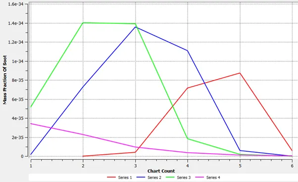
Soot emissions
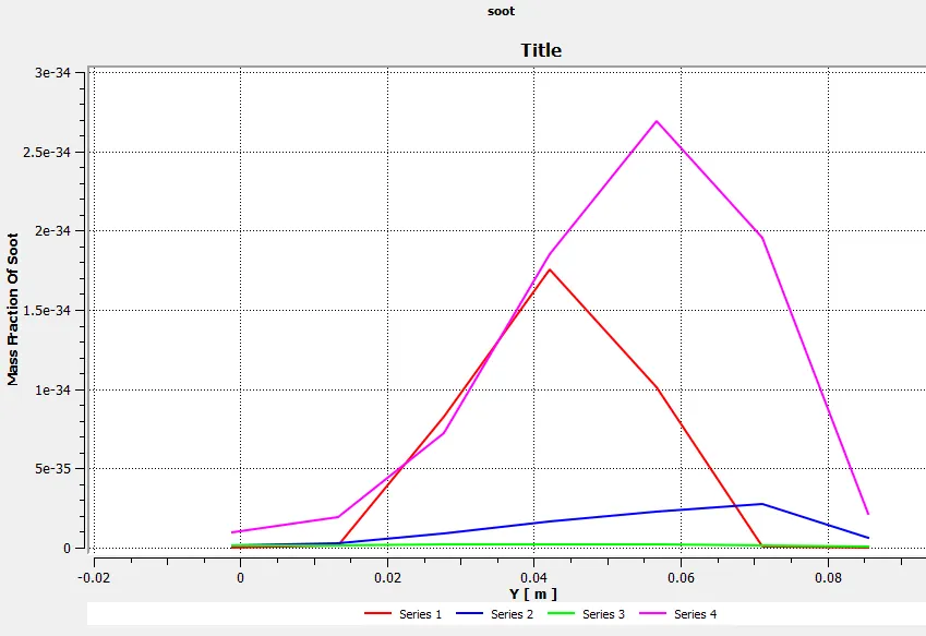
The Soot emissions are produced when there are unburnt carbon particles at the end of the combustion.
Reduce NOx & Soot Emissions
The NOx & soot can be controlled with the help of the after-treatment devices but in order to reduce the emissions at the outlet of the cylinder the fuel injected can be altered. So we mix water with methane in a small proportion. Add the water content in the fuel from 5% to 40% and the effects of this observed.
Average mass fraction of NOx at a different location along the x-axis
There are two factors that govern the NOx emission i) Max temperature ii) Excess Oxygen. The excess oxygen in the combustion depends on the stoichiometric ratio of the fuel & air which can be controlled using an injector & ECU units. The next parameter is the max temperature which depends on the fuel calorific value by adding water content its calorific value reduces thereby the maximum temperature reduces, so the NOx emissions reduce linearly with the increase in the water content in fuel.
The Soot emissions are governed by factors like incomplete combustion, rich stoichiometric ratio & combustion rate, etc. So the varying the fuel concentration alone doesn't affect much in Soot emissions even though there is a drop in soot value the other parameters like fuel mixing also important so the variation of soot emission vs Mole concentration is not linear.
Case-1 H2o mass fraction =0.05
Co2 plots at all the 4 line probes
h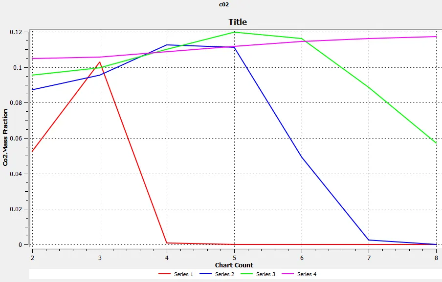
H20 plot
Ch4 Plot
N2 plot
O2 plot
Nox plot
Case-2 H2o mass fraction =0.2
Co2 plot
H2o plot
Ch4 plot
N2 plot
O2 plot
Nox plot
Case-3 H2o mass fraction =0.3
Co2 plot
H2o plot
Ch4 plot
N2 plot
O2 plot
Nox plot
Case-4 H2o mass fraction = 0.4
Nox plot
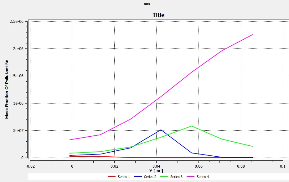
O2 plot
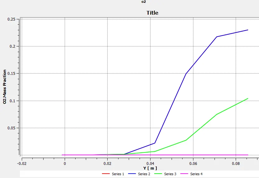
N2 plot
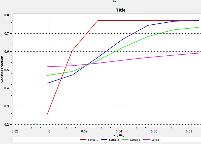
Ch4 plot
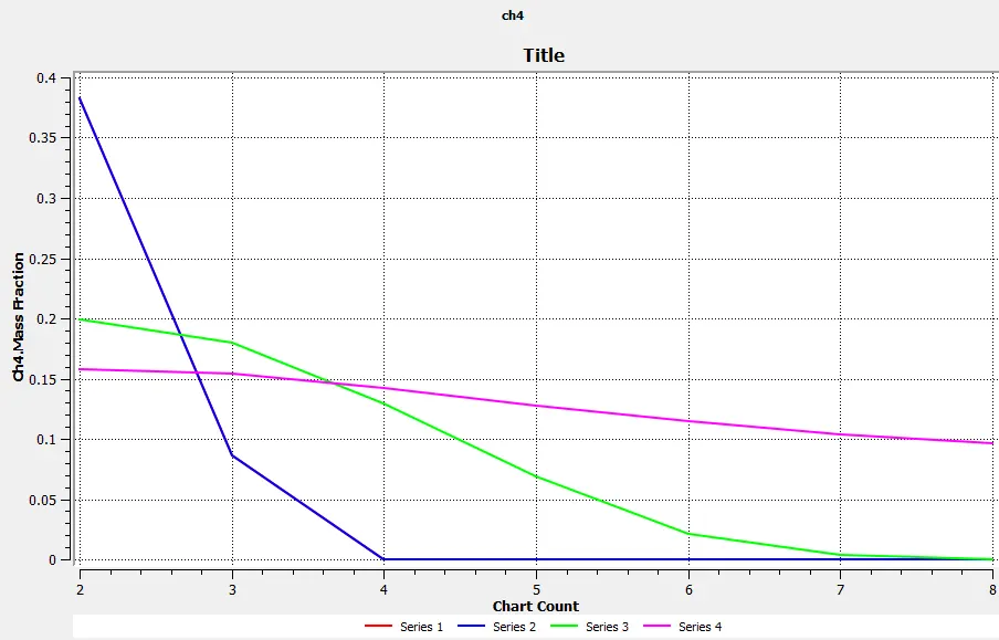
H2o plot
Co2 plot
Soot plot
Conclusive Effect on soot and NOX formation-
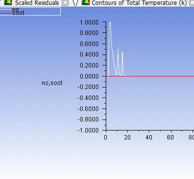
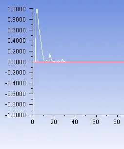
To study the effects of change of water content in the exaust composition of NOx and Soot,an area weighted average plot of the soot and nox content is monitored at the outlet of the combustion chamber.
The following plots were obtained for different h2o content in the inlet fuel.
H20 40 %
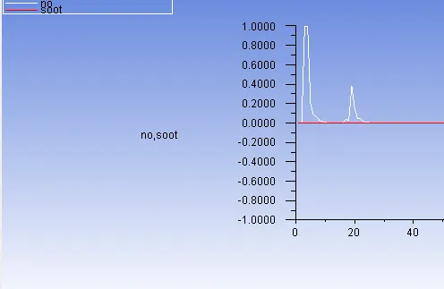
H2o- 20%
H2o -10%
H20-0.05%
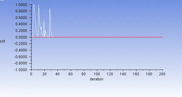
As we can see from the above graphs ,the soot content is very close to zero and is not too much effected by the changing water content.
The Nox net value can be equated to area under the graph and we can observe the the minimum Nox emmisions occur at a inlet water content value of 10%.