Challenge on Combustion
COMBUSTION SIMULATION
OBJECTIVE :
PART I:
To perform a combustion simulation on the combustor model and plot the variation of the mass fraction of the different species’ such as CO2,H2O,CH4,N2,O2,NOx emissions & Soot formation in the simulation using line probes at different locations of the combustor.
PART II:
To perform the combustion simulation on the combustor model by adding water on to the fuel which is being used for combustion from 5 % to 30 % by mole and to observe its effect on the NOx emissions and soot formations.
DESCRIPTION:
Combustion is a chemical process in which a substance reacts rapidly with oxygen and gives off heat. The original substance is called the fuel, and the source of oxygen is called the oxidizer. The fuel can be a solid, liquid, or gas, although for airplane propulsion the fuel is usually a liquid. The oxidizer, likewise, could be a solid,liquid or gas but is usually a gas (air) for airplanes. For model rockets, a solid fuel and oxidizer is used.During the combustion process, as the fuel and oxidizer are turned into exhaust products, heat is generated. Interestingly, some source of heat is also necessary to start combustion. Gasoline and air are both present in your automobile fuel tank; but combustion does not occur because there is no source of heat. Since heat is both required to start combustion and is itself a product of combustion, we can see why combustion takes place very rapidly. Also, once combustion gets started, we don't have to provide the heat source because the heat of combustion will keep things going.
During combustion, new chemical substances are created from the fuel and the oxidizer. These substances are called exhaust. Most of the exhaust comes from chemical combinations of the fuel and oxygen. When a hydrogen-carbon-based fuel (like gasoline) burns, the exhaust includes water (hydrogen + oxygen) and carbon dioxide (carbon + oxygen). But the exhaust can also include chemical combinations from the oxidizer alone. If the gasoline is burned in air, which contains 21% oxygen and 78% nitrogen, the exhaust can also include nitrous oxides (NOX, nitrogen + oxygen). The temperature of the exhaust is high because of the heat that is transferred to the exhaust during combustion. Because of the high temperatures, exhaust usually occurs as a gas, but there can be liquid or solid exhaust products as well. Soot, for example, is a form of solid exhaust that occurs in some combustion processes.
The principal nitrogen pollutants generated during combustion are nitric oxide (NO) and nitrogen dioxide (NO2), collectively referred to as NOx.Although there is evidence proving NOx, in itself, is harmful to humans, the main reason NOx is considered an environmental problem is because it initiates reactions that result in the production of ozone (O3) and acid rain. By controlling NOx levels, along with the other pollutants, the levels of acid rain and ozone can be reduced.Primarily there are two types of NOx :
- Thermal NOx
- Fuel NOx
- Prompt NOx
Thermal NOx is formed when nitrogen and oxygen in the combustion air combine with one another at the high temperatures in a flame. Thermal NOx makes up the majority of NOx formed during the combustion of gases and light oils. The rate of NOx formation generally increases significantly above 2,800°F flame temperature.Fuel NOx is formed by the reaction of nitrogen bound in the fuel with oxygen in the combustion air. It is rarely a problem with gaseous fuels. But in oils containing significant amounts of fuel-bound nitrogen, fuel NOx can account for up to 50% of the total NOx emissions.Prompt NOx is formed from the rapid reaction of atmospheric nitrogen with hydrocarbon radicals. Prompt NOx is generally minor compared to the overall quantity of NOx generated from combustion. However, as NOx emissions are reduced to extremely low limits, the contribution of this source becomes more important.
Soot is a mass of impure carbon particles resulting from the incomplete combustion of hydrocarbons It is more properly restricted to the product of the gas-phase combustion process but is commonly extended to include the residual pyrolysed fuel particles such as coal,charred wood, and petroleum coke that may become airborne during pyrolysis and that are more properly identified as cokes or char.
NUMERICAL SIMULATION :
1. GEOMETRY:
A 2D combustor model has been used for the numerical simulation as it would be beneficial to save the computational cost and also using the 2D model,it will provide results similar to that of the 3D model simulation
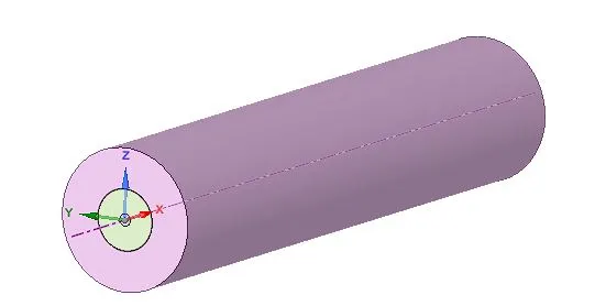
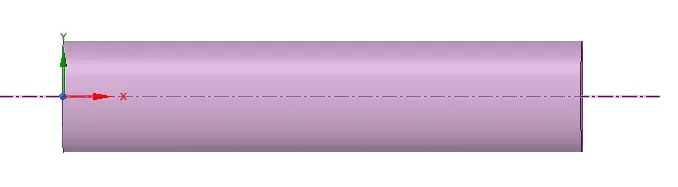
The above 3D geometry of the combustor has been made into 2D model using spaceclaim and this 2D geometry has been used for the analysis

The problem will be solved as an axi-symmetric problem.
2. MESHING:

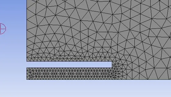
The meshed profile of the combustor has been shown above.For both the part of the simulation ie,PART I and PART II same mesh profile has been employed.
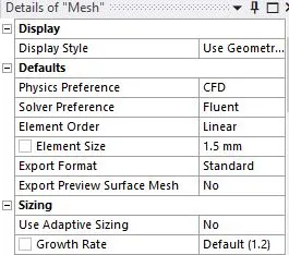
- ELement Type : Triangular
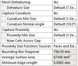
- Number of Elements : 63,072
- Number of Nodes : 32,166
The mesh metric plot for the above mesh profile has been shown below:
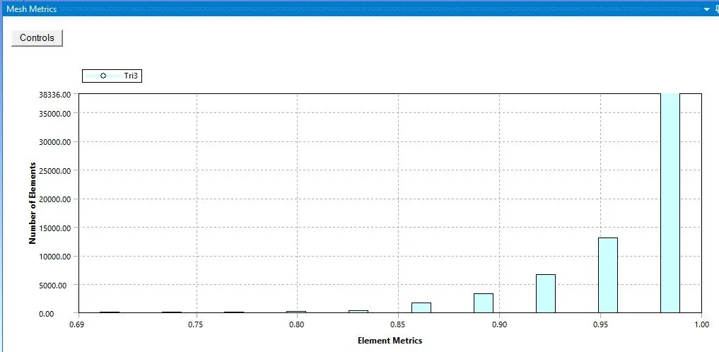
- Mesh metric for element quality
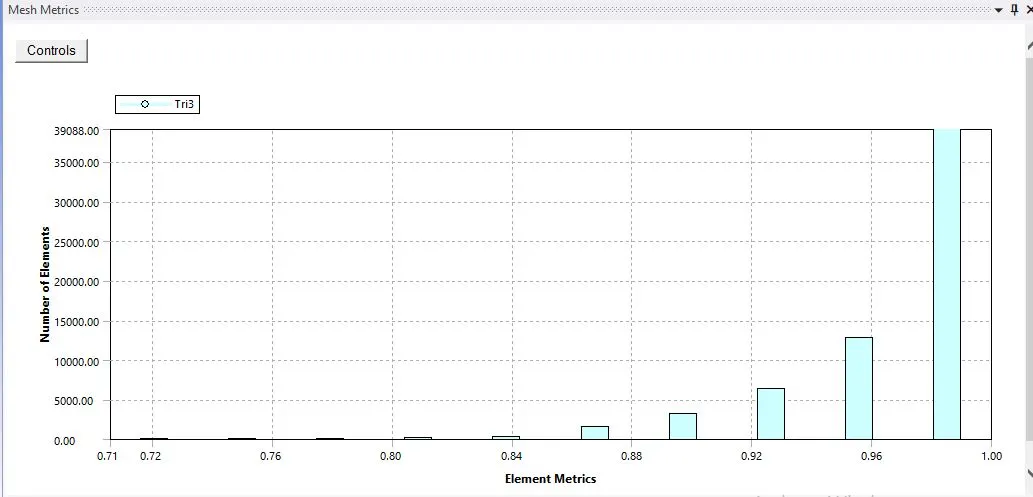
- Mesh metric for orthogonal quality of mesh elements
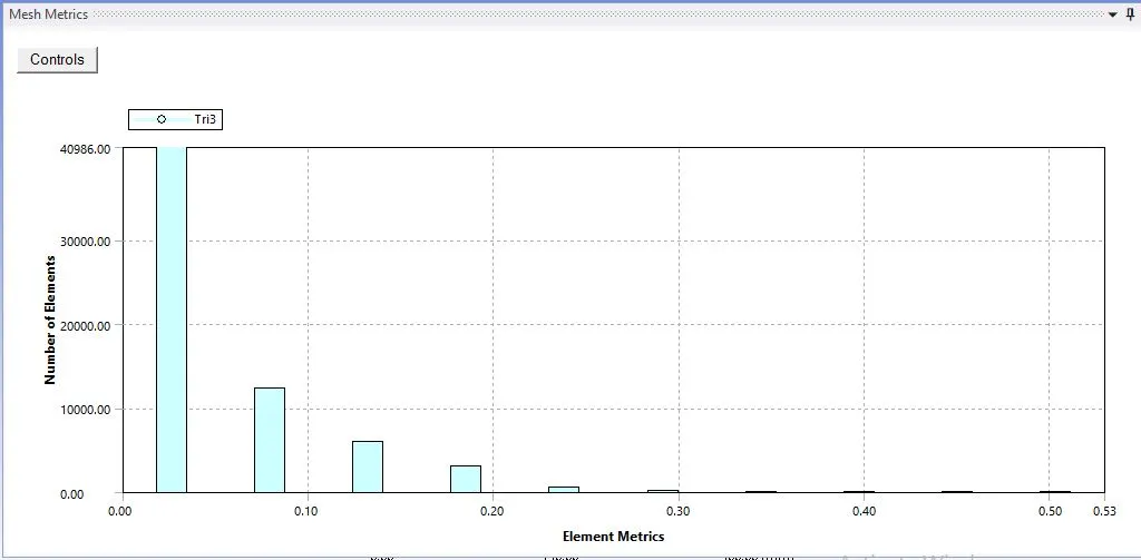
- Mesh metric for the skewness of the elements.
From the above mesh metric,it is clear that the meshing provided to the geometry is descent.As the average skewness of the elements is less than 0.8 and orthogonal quality of the elements is close to 1.
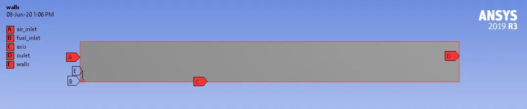
- Named selection of the geometry is provided as shown above.
3. SETUP:
Solver:
-Type : Pressure-Based
-Time : Steady
-Velocity Formulation : Absolute
- Axisymmetric
Model :
-Energy : ON
-Viscous Model : Standard k-epsilon Model
-Species : ON
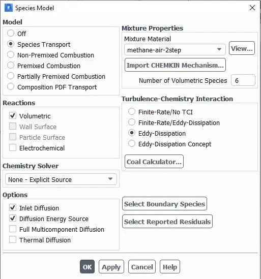
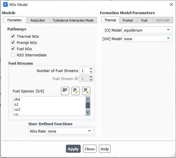
- Nox Model :
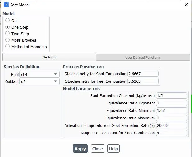
- Soot Model:
Boundary Conditions :
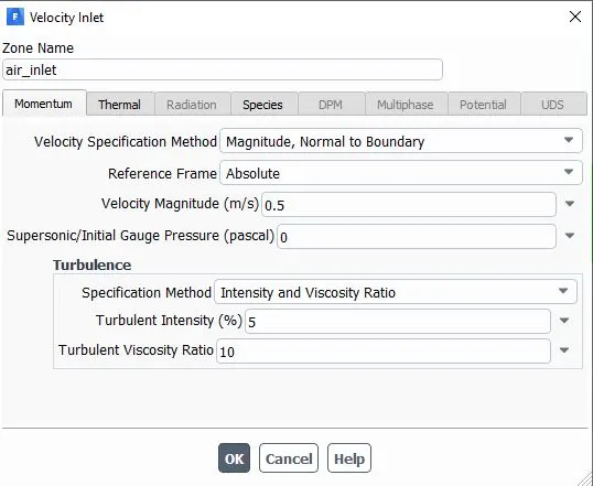
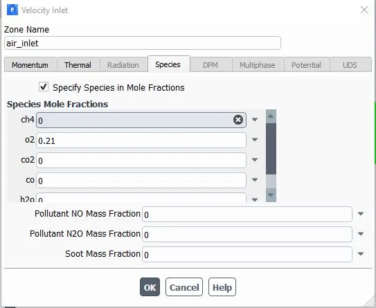
PART I:
-air_inlet : Velocity Inlet
-fuel_inlet : Velociy Inlet
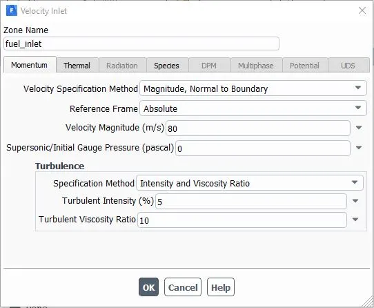
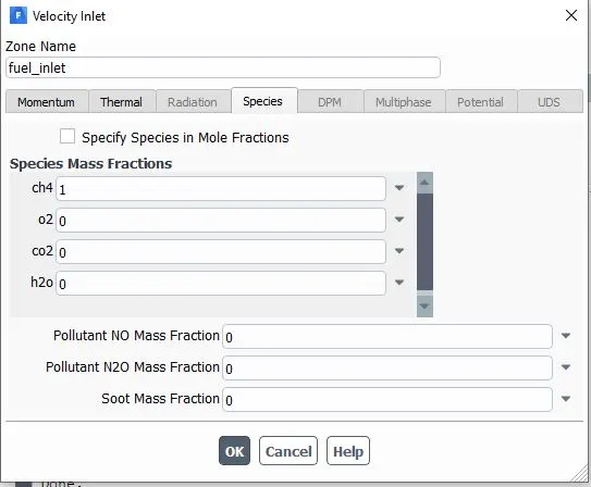
-axis : Axis Boundary condition
-Outlet : Pressure-Outlet
-wall : No slip Condition
PART II:
-air_inlet :Velocity Inlet
-fuel_inlet:Velocity Inlet
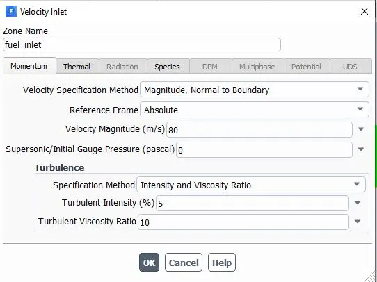
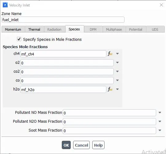
- Two parameter has been set for the values of mole fractions of Ch4 and H2o,for conducting a parametric study.
-axis : Axis Boundary condition
-Outlet : Pressure-Outlet
-wall : No slip Condition
Calculation :
-Coupled Solver
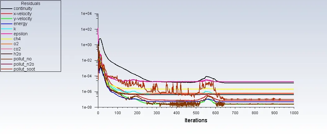
-Number of Iteration :1000
4.SOLUTION & RESULTS :
PART I:
1. Residual Plot:
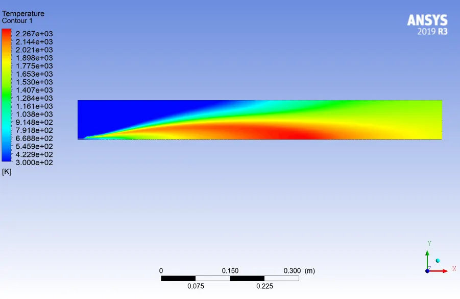
2.Temperature Contour :
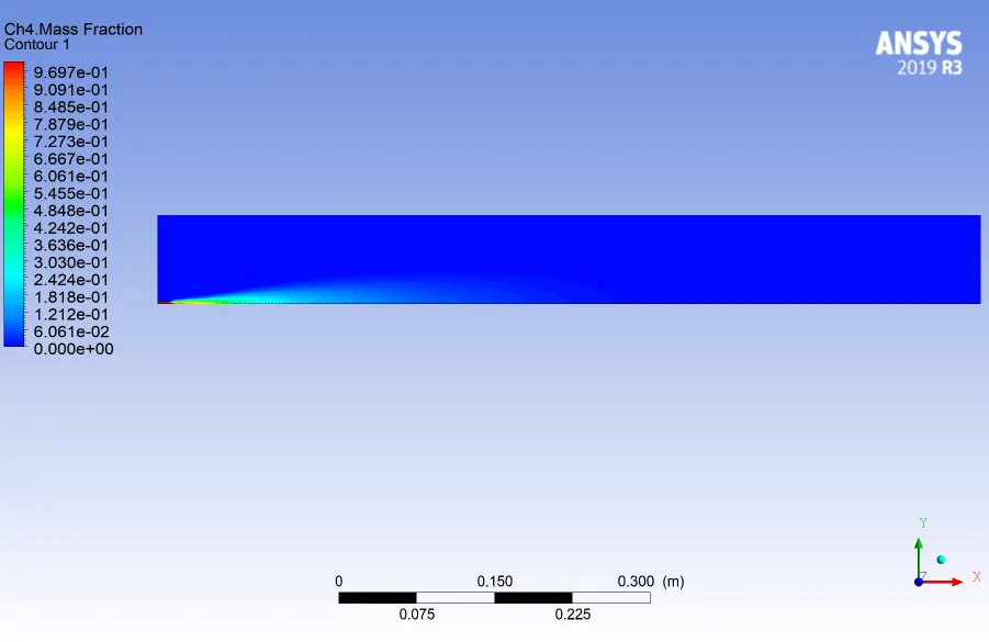
3. Ch4 mass-fraction contour:
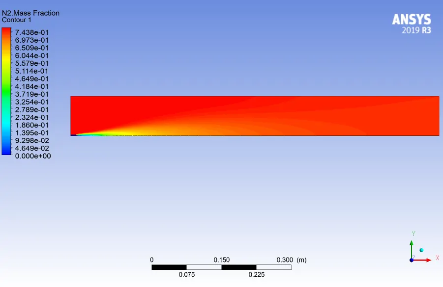
4. N2 mass-fraction contour:
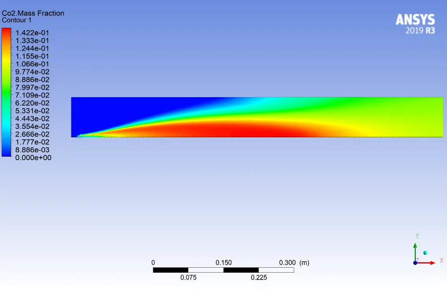
5.CO2 mass-fraction contour:
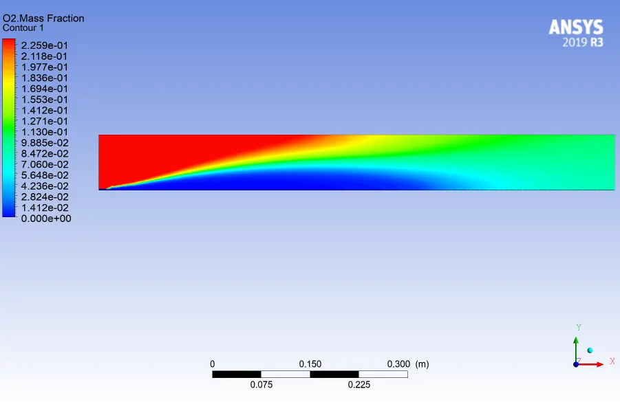
6. O2 mass-fraction contour:
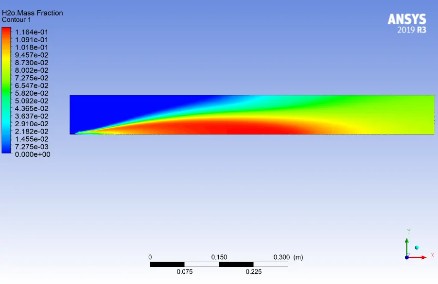
7. H2o mass-fraction contour:
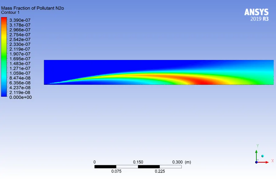
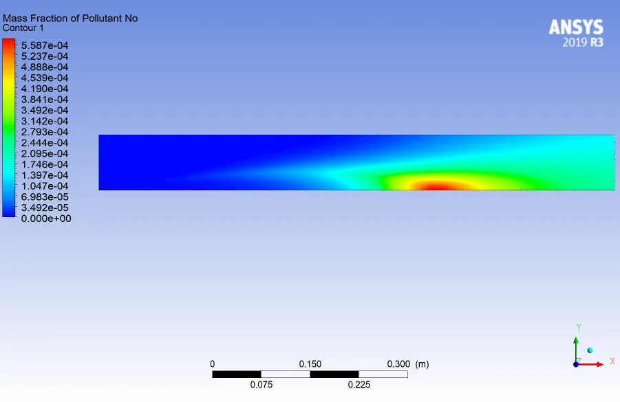
8.NOx mass-fraction contour:
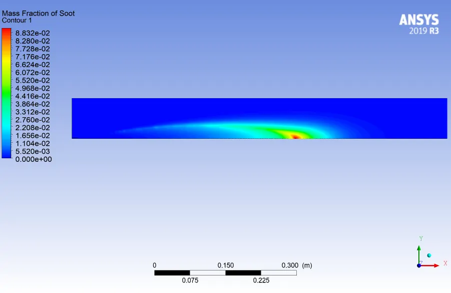
9.Soot mass-fraction contour:
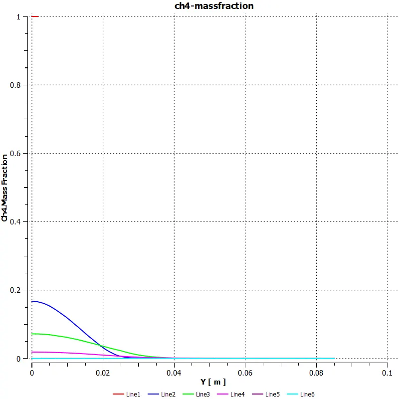
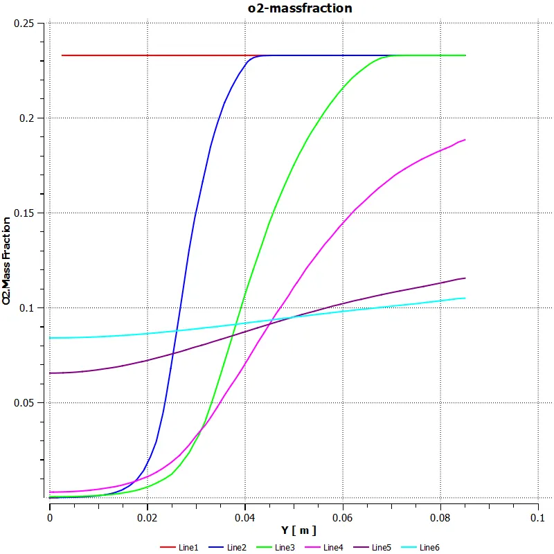
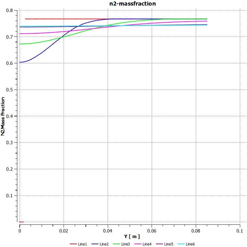
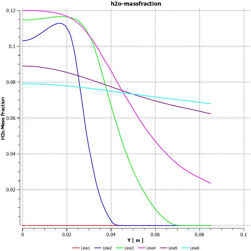
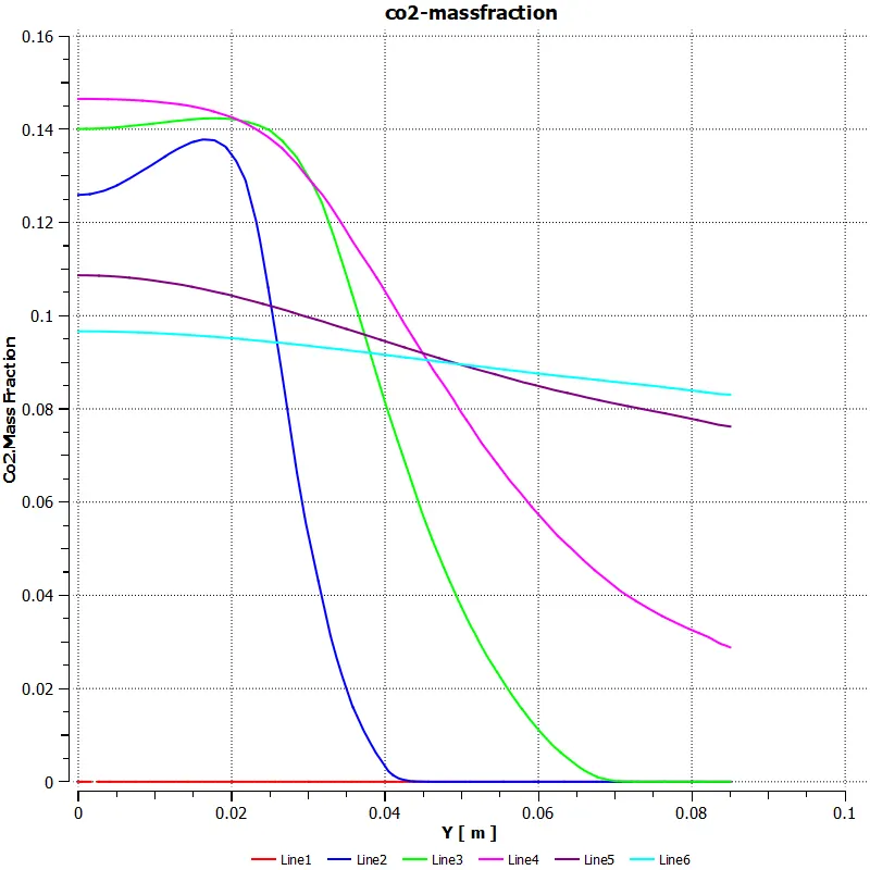
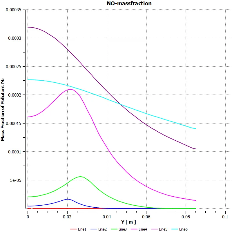
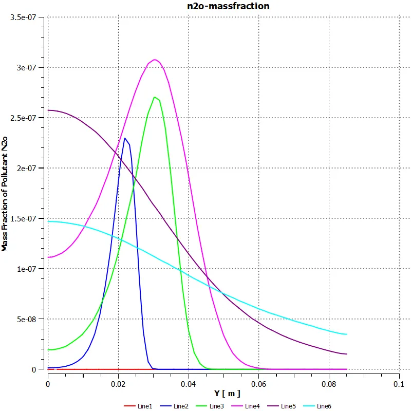
To understand the variation of the components during combustion in different areas of the combustor,line plots has been made in CFD-post and the results were plotted using charts and visualised.

6 Lines has been made starting from the inlet of fuel and air to the outlet of the combustor and the results were plotted:
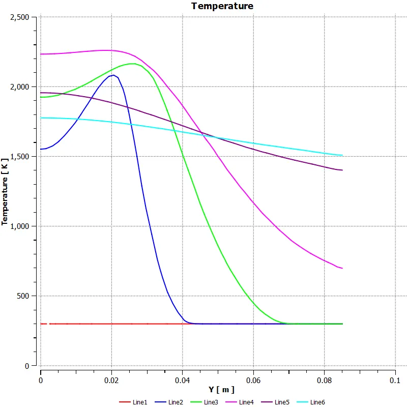
- The maximum temperature in the combustor during combustion has been recorded in the line 4 on the combustor,ie almost at the ,middle portion of the combustor
- Maximum temperature obained was 2267 K.
Variation of mass-fractions of ch4,o2,N2,h20,co2 along the length of the combustor is given below:
Mass-fraction os te pollutants ie,NOx & soot are given below:
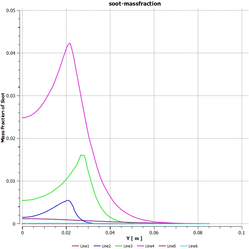
Numerous results can be drawn from the plots that are obtained:
- Maximum temperature during the the combustion in the combustion occur somewhere in the middle of the combustor and not at the outlet.
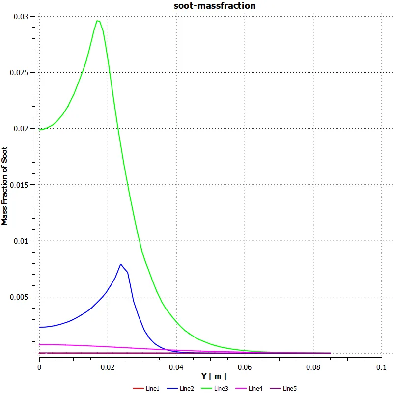
- Soot formed during the combustion is having a maximum mass fraction of 0.042 , eventhough this amount of soot is not formed at the outlet,still it effects the efficency of combustion.
- NOx formed at the outlet accounts for a mass fraction of 0.000225 , which will become significant,in a time where government is adopting stringent policies to reduce the emission of NOx and soot.
Thus,inorder to reduce the emission of NOx and soot,water is added in small quantites to the fuel.5% to 30% of water was added along with the fuel and the results are obtained by parametric study.
PART II :
Parametric study was conducted , by varying the amount of water that was added to the fuel,and the results obtained are tabulated below:
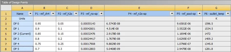
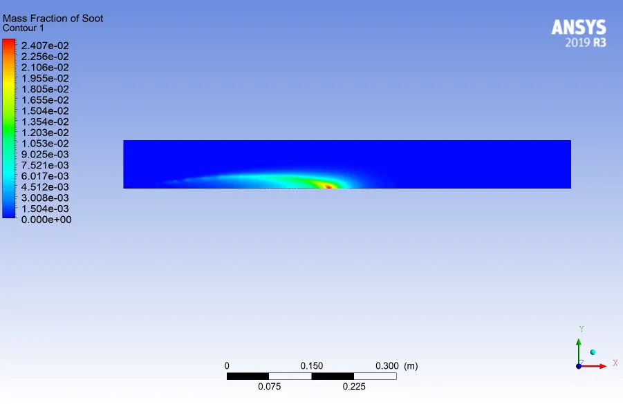
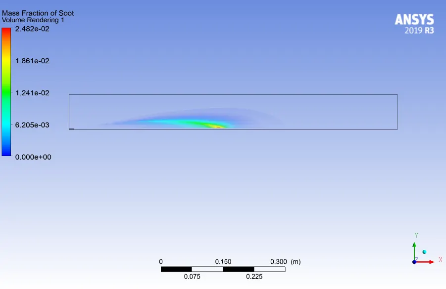
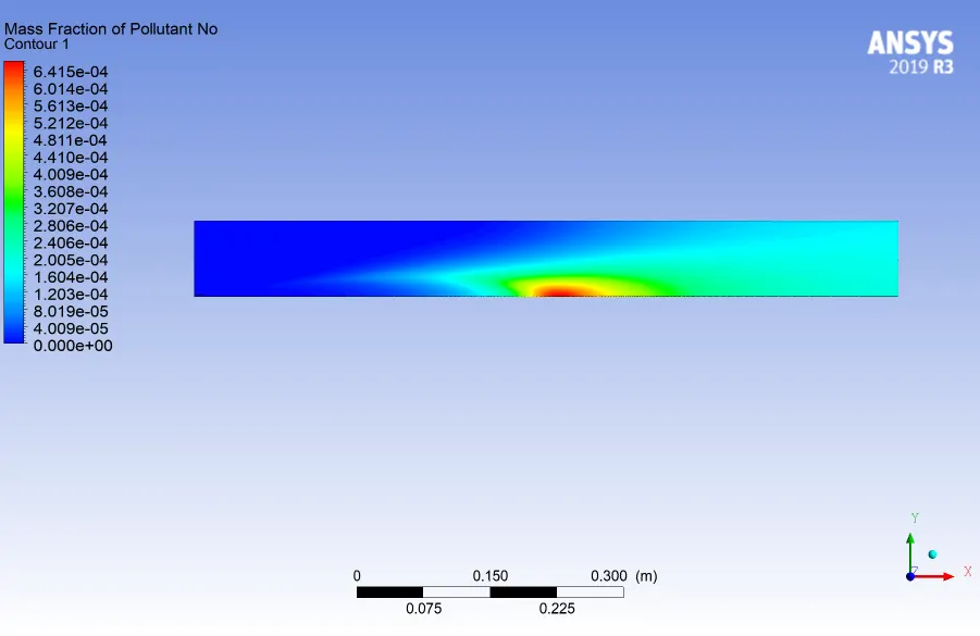
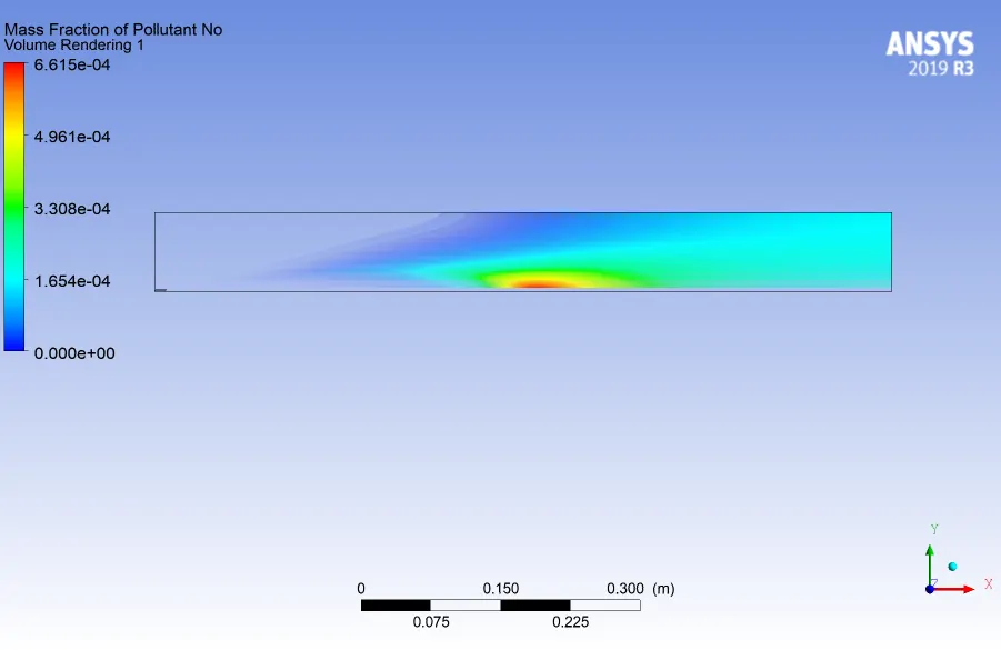
- Variation in the mass fraction of NOx( NO & N2O) ,soot and the temperature achieved at the outlet has been studied by varying the mole fraction of water added to the fuel
Design Point 0 :
mole fraction of ch4 = 0.95
mole fraction of h2o = 0.05
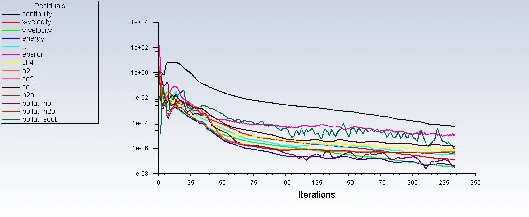
1.Residual Plot:
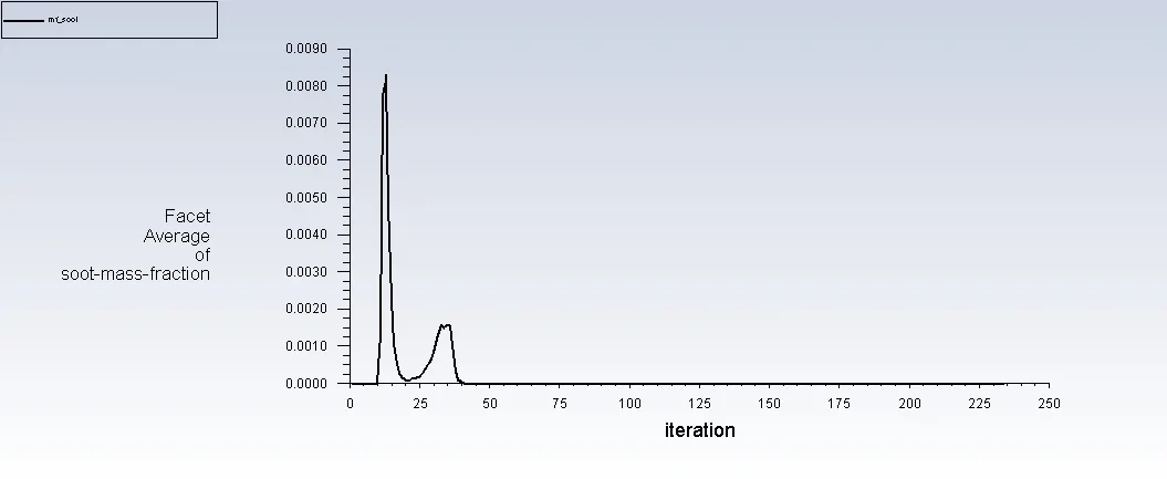
2. mass-fraction of soot at outlet
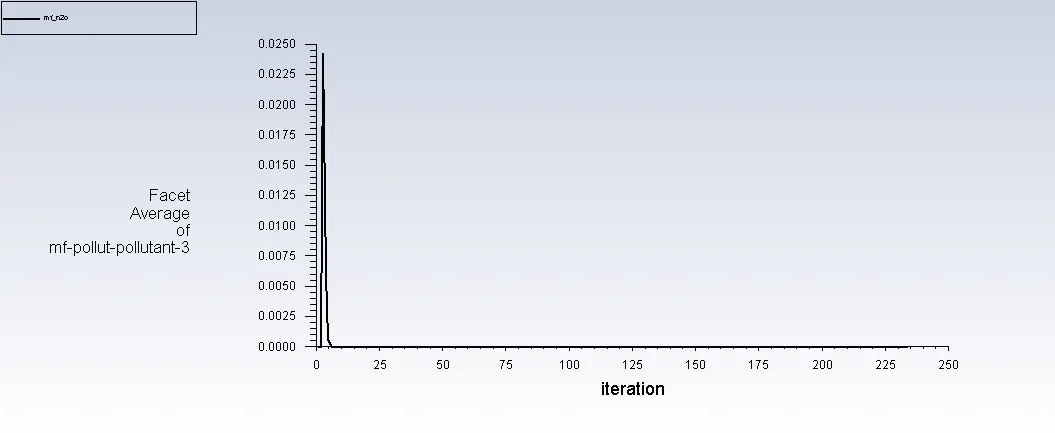
3.mass fraction of n2o at outlet:
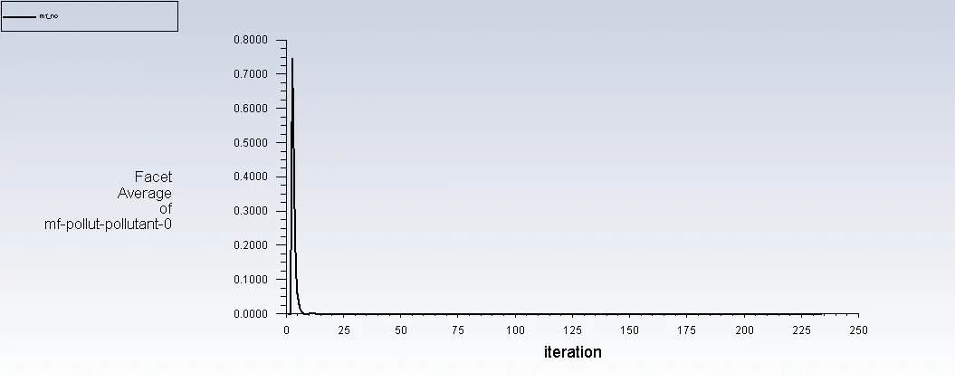
4.mass fracion of NO at outlet:
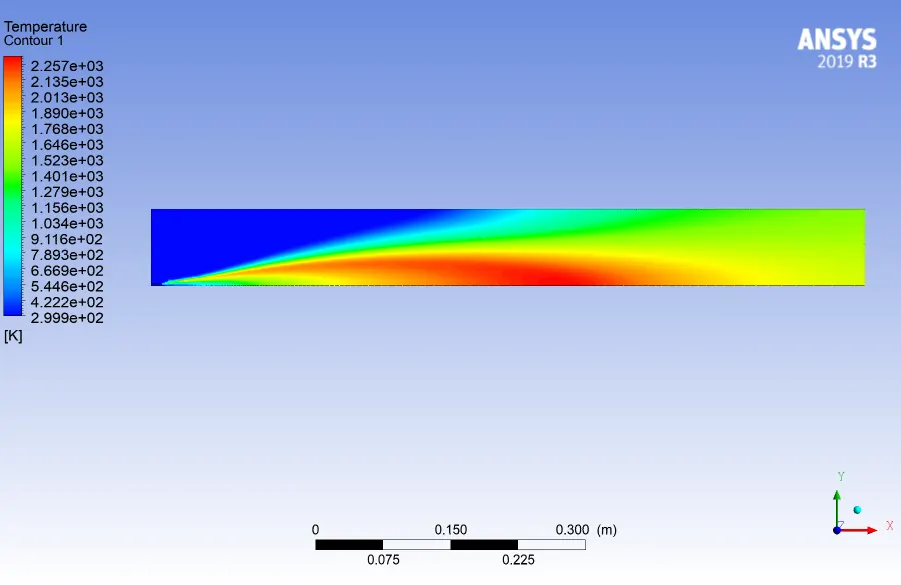
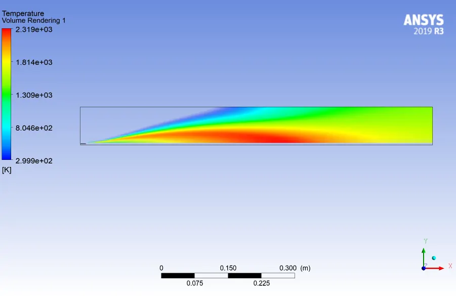
5. Temperature contour &Volume Rendering Plot:
6. contour & volume rendering plot for mass fraction of soot:
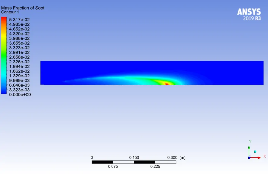
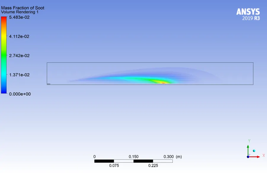
7.contour & volume rendering plot for mass fraction of N2O:
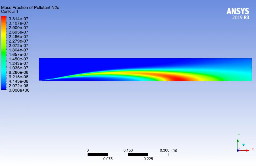
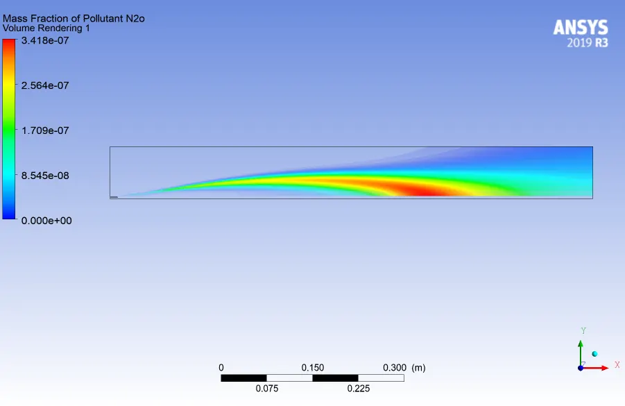
8.contour & volume rendering plot for mass fraction of NO:
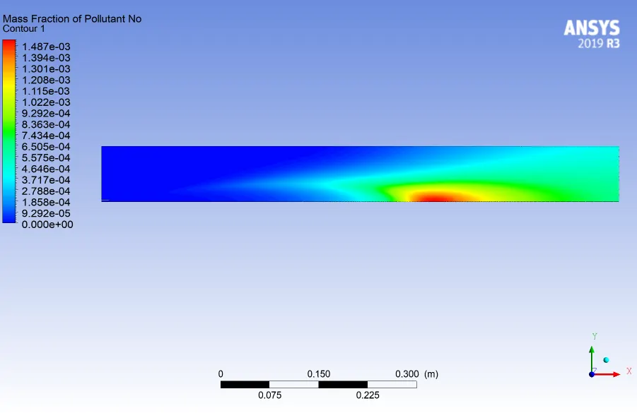
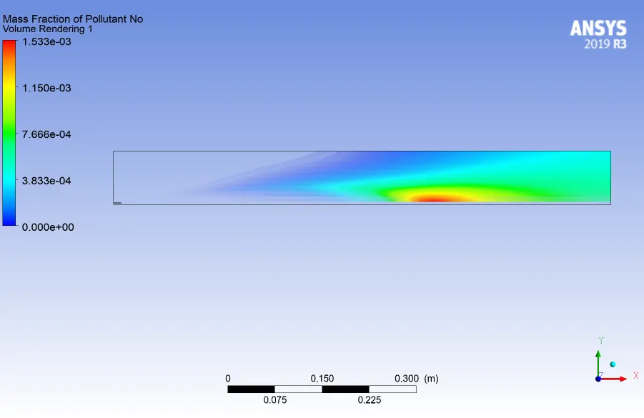
Several lines has been created to study the variation of soot and NOx formation along the length of the combustion:
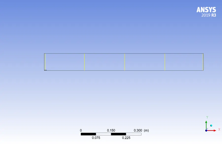
- Variation of soot along the line plotted:
- Variation of NOx along line plotted:
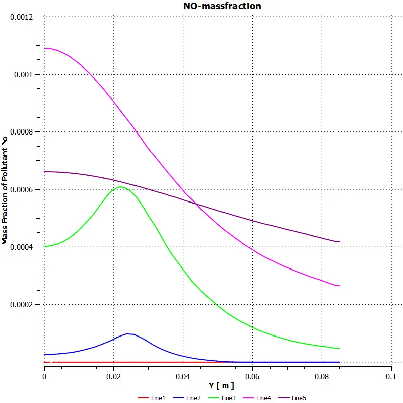
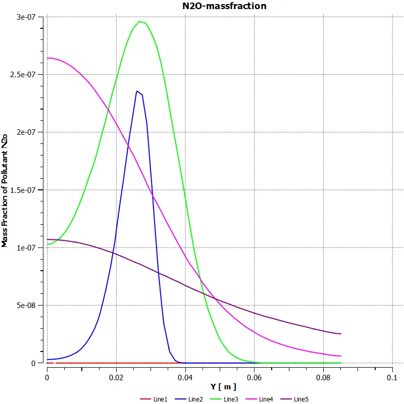
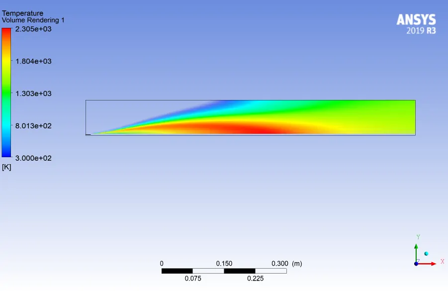
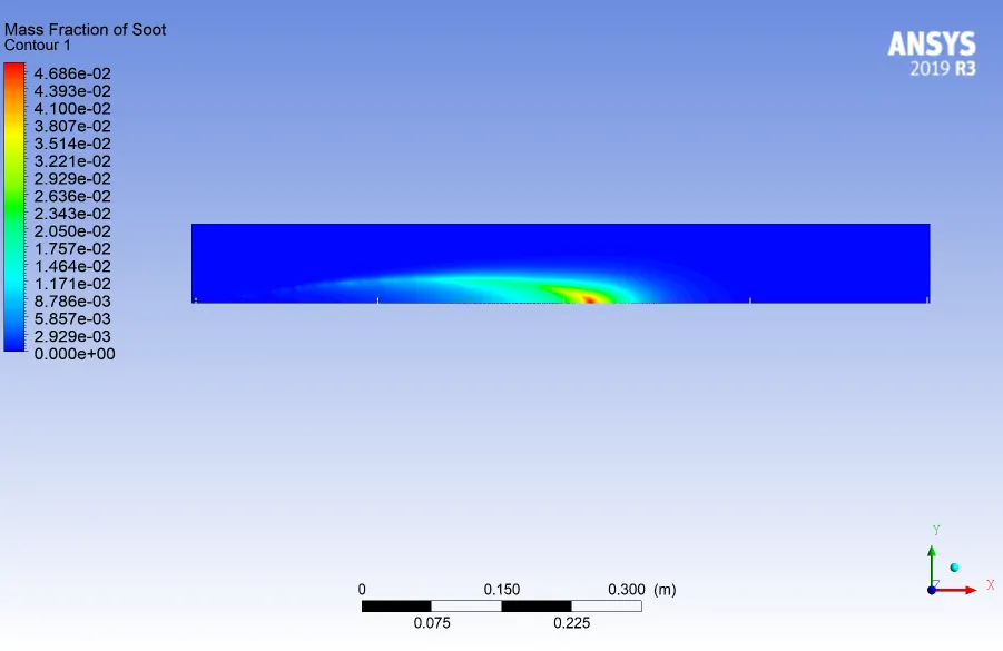
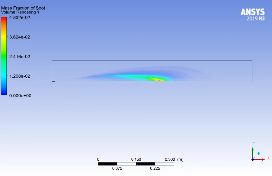
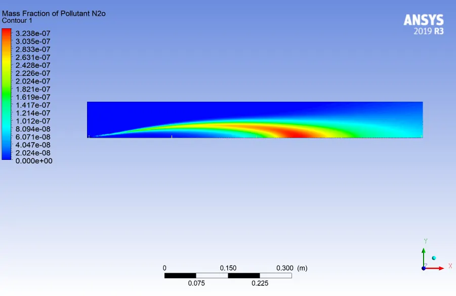
Design Point 1:
mole fraction of ch4 = 0.9
mole fraction of h2o = 0.1
1.Residual Plot:
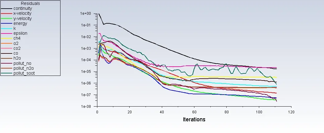
- The flow converged for an iteration of 110.
2.Contour & Volume rendering plot for Temperature:
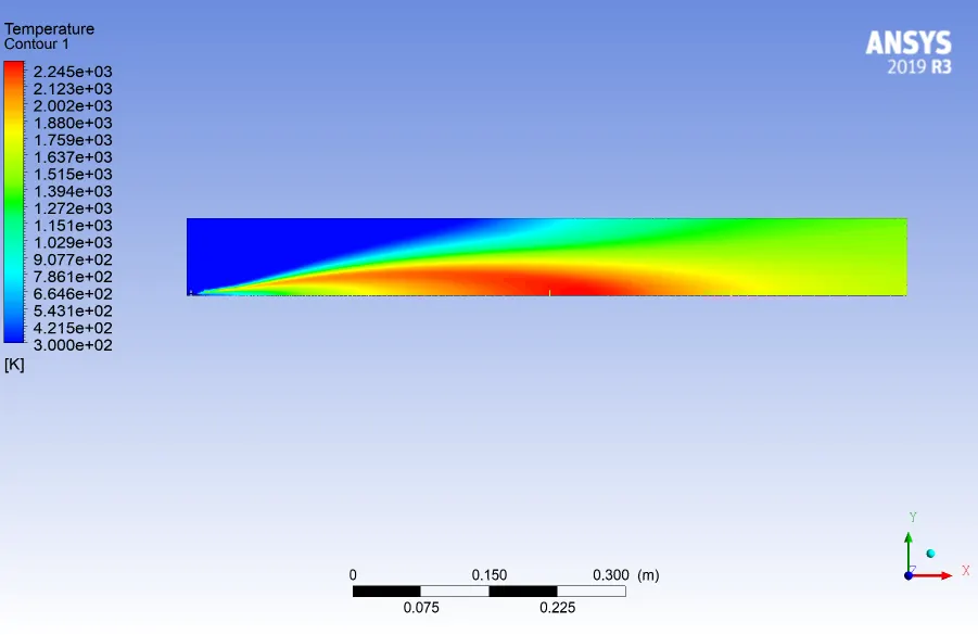
3.Contour & Volume rendering plot for massfraction of Soot:
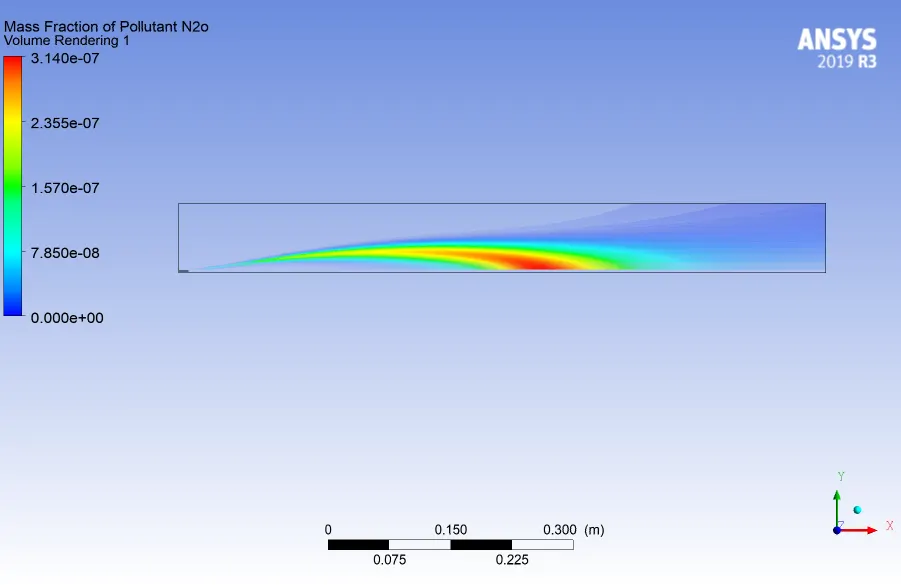
4.Contour & Volume rendering plot for massfraction of N2o:
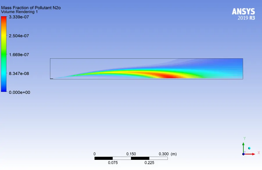
5.Contour & Volume rendering plot for massfraction of NO:
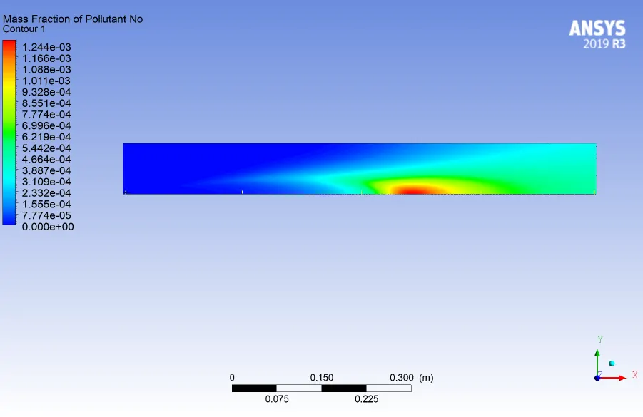
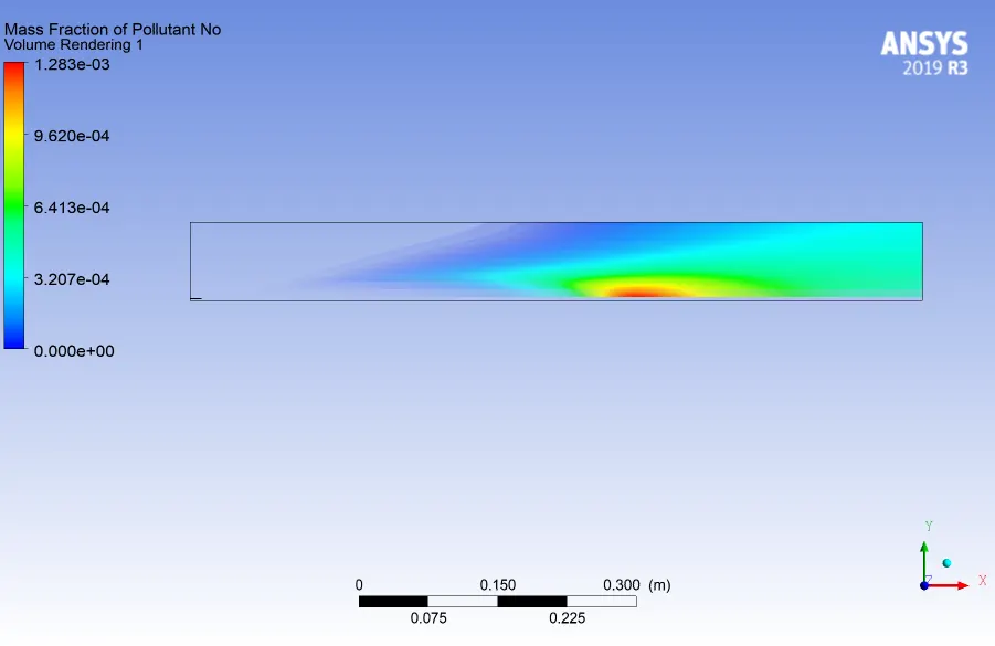
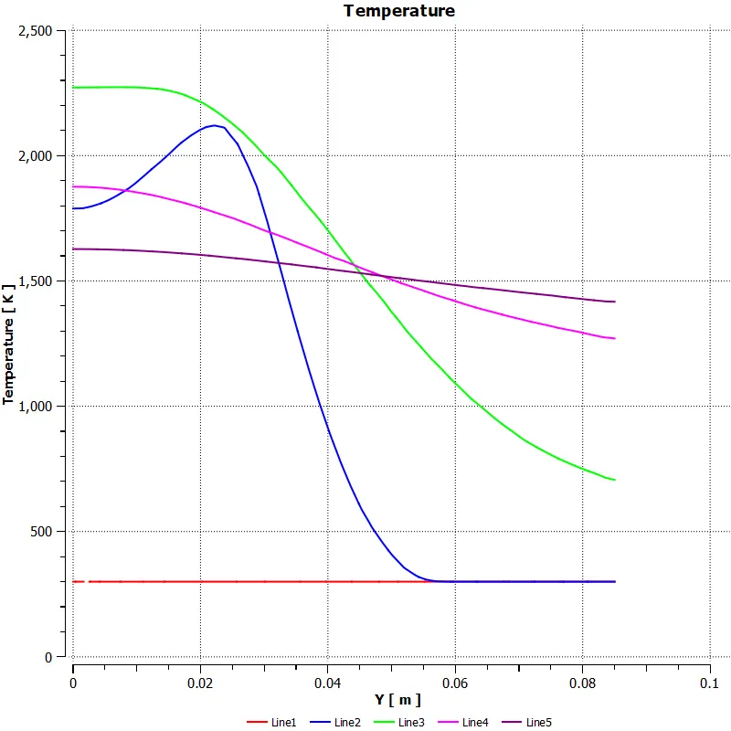
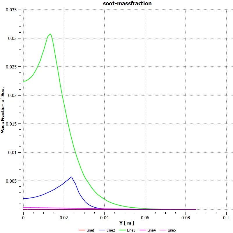
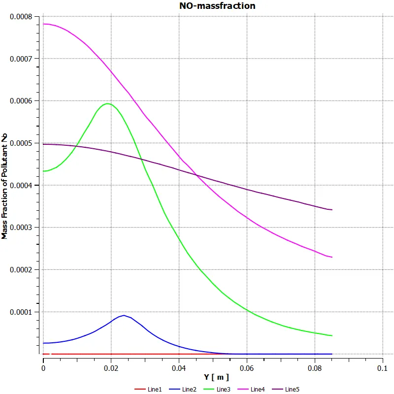
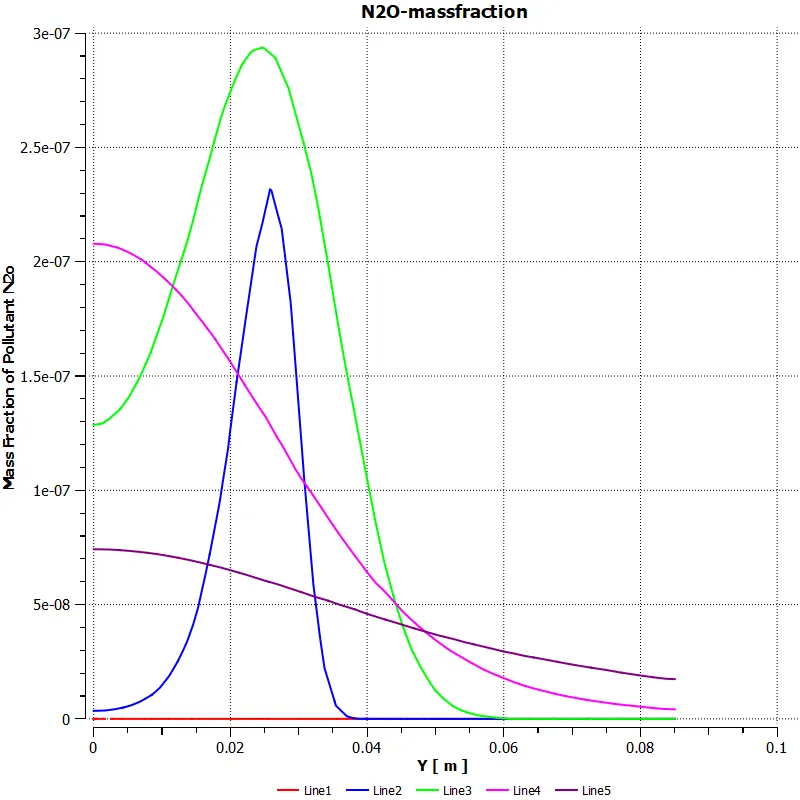
Several lines has been created to study the variation of soot and NOx formation in the combustor:
- Variation of temperature along the line plotted:
- Variation of soot formation along the line plotted:
- Variation of NOx formation along the line plotted:
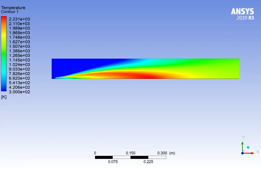
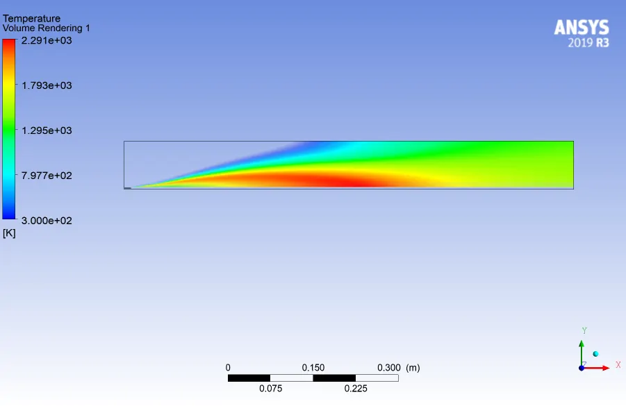
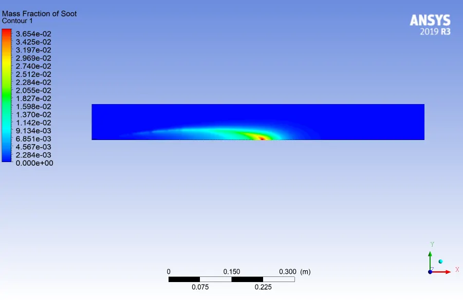
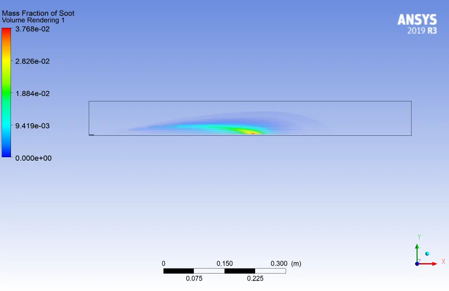
Design Point 2:
mole fraction of ch4 = 0.85
mole fraction of h2o = 0.15
1.Residual:
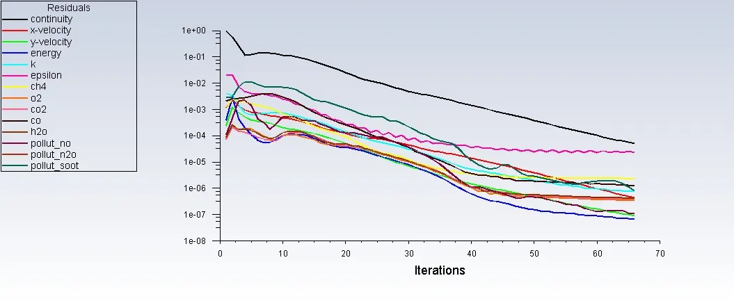
- Flow converged for an iteration of 65.
2.Contour & Volume rendering plot for temperature:
3.Contour & Volume rendering plot for massfraction of soot:
4.Contour & Volume rendering plot for massfraction of N2O:
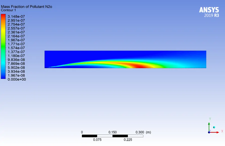
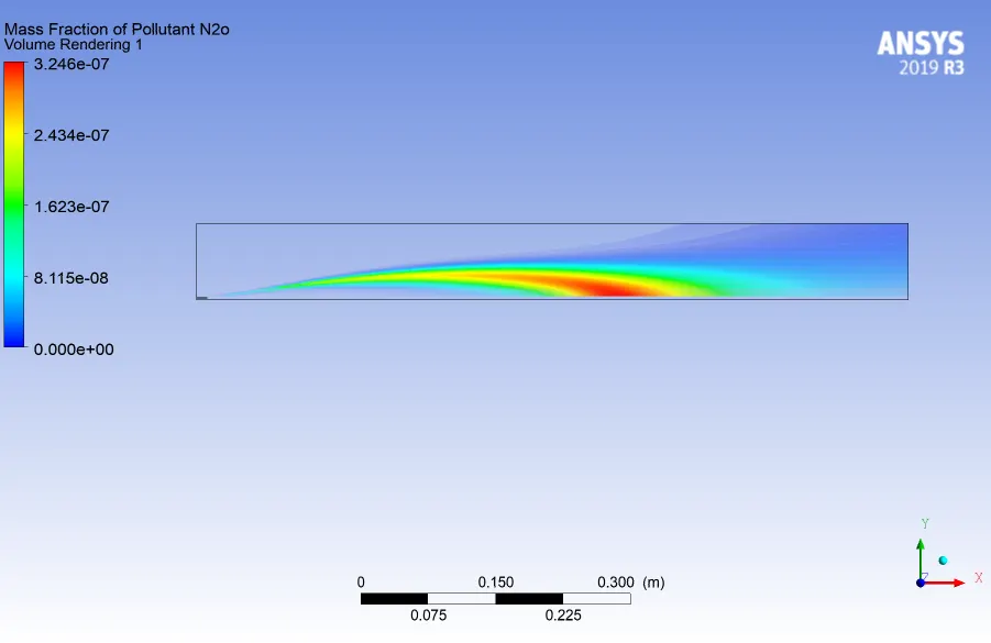
5.Contour & Volume rendering plot for massfraction of NO:
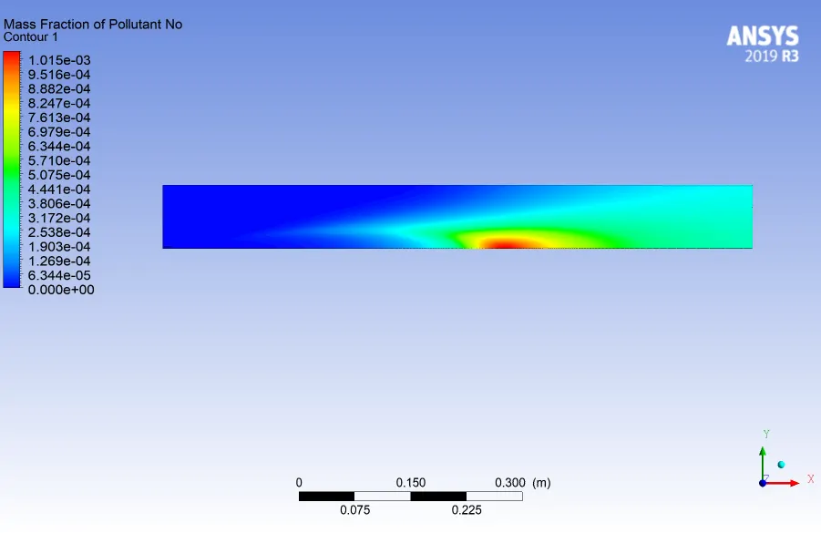
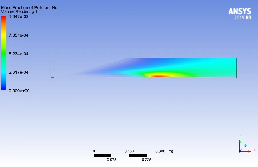
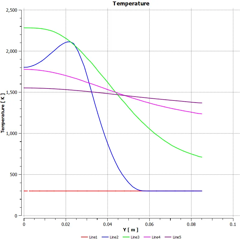
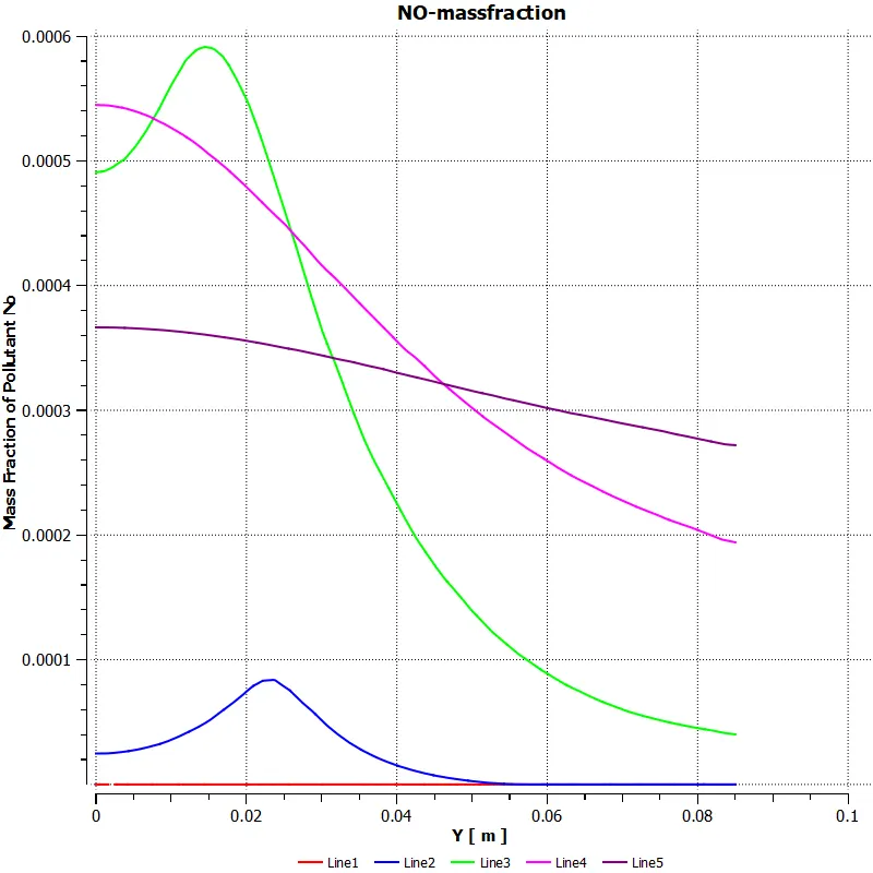
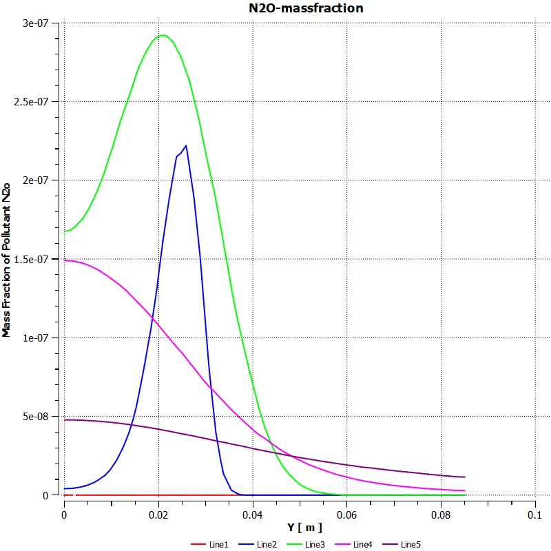
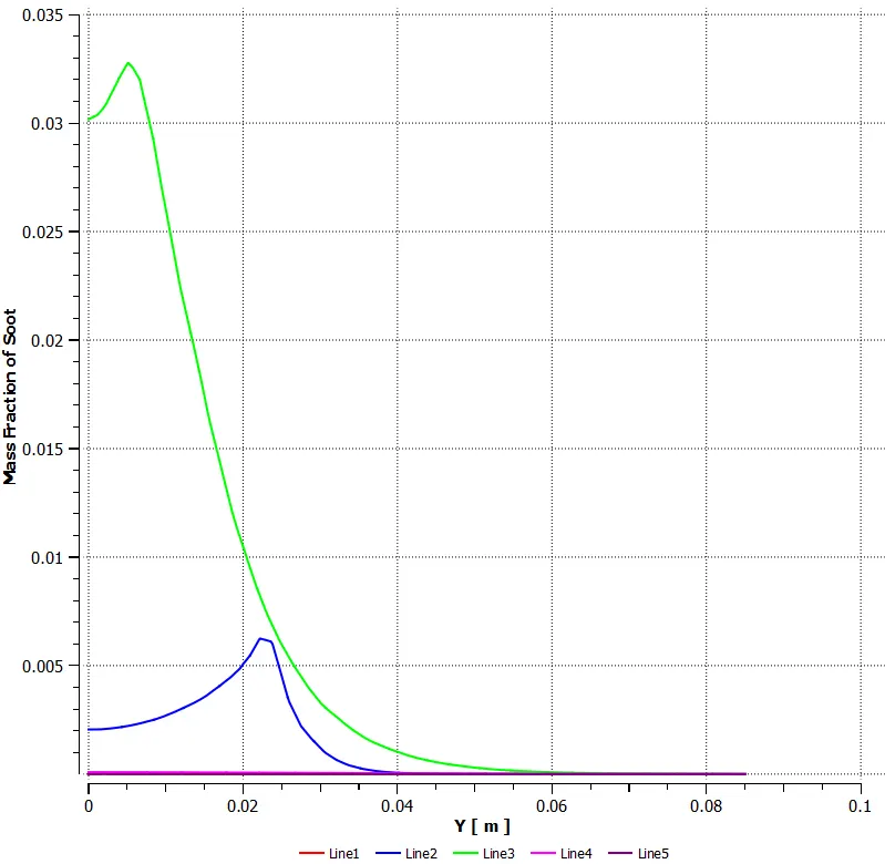
Line plots on the model is show below:
- Variation of temperature along the line plotted:
- Variation of NOx formation along the line plotted:
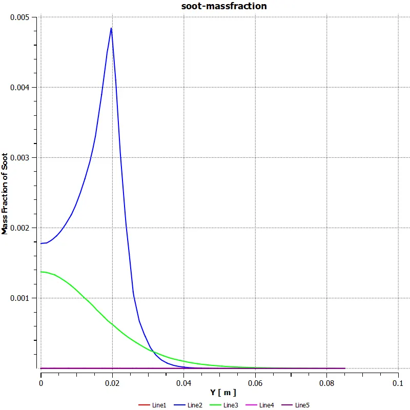
- Variation of soot formation along the line plotted:
Design Point 3:
mole fraction of ch4 = 0.80
mole fraction of h2o = 0.20
1.Residual:
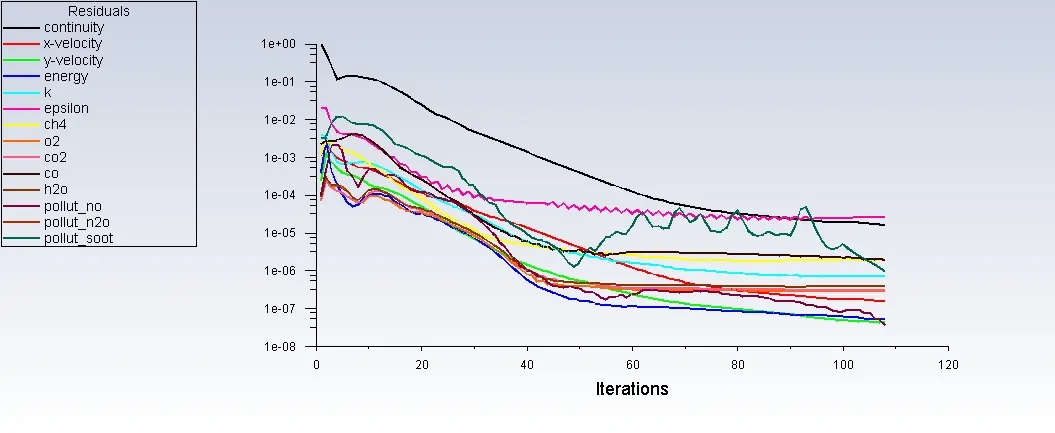
- Solution converged at about an iteration of 110
2.Contour & Volume rendering plot of Temperature:
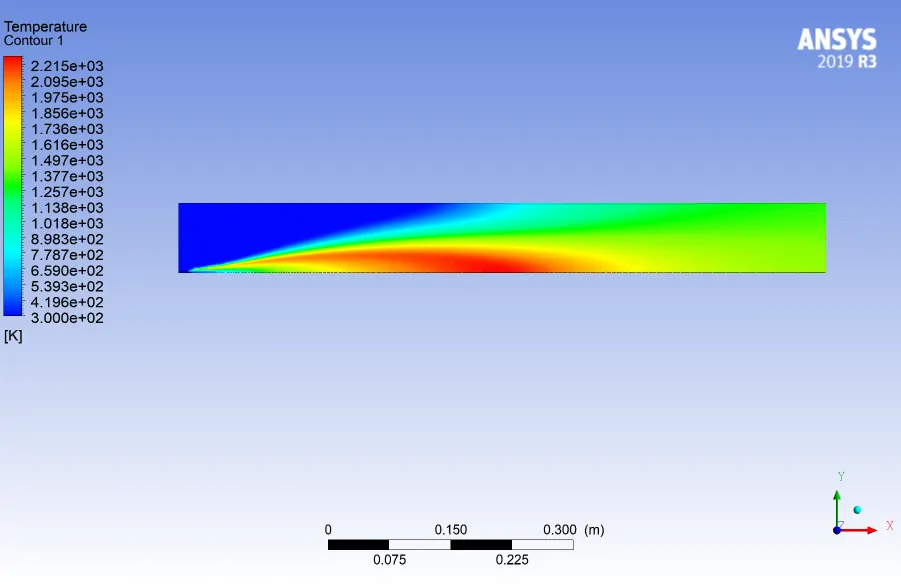
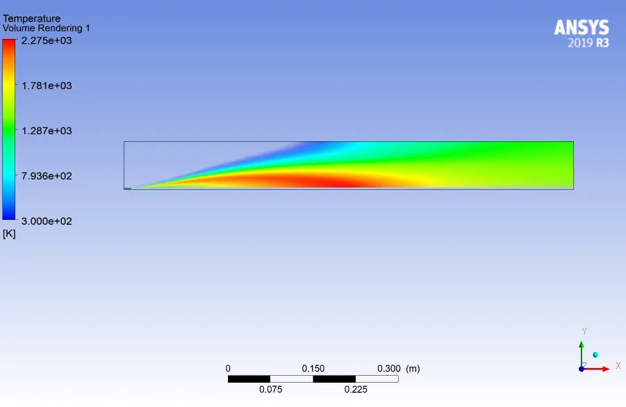
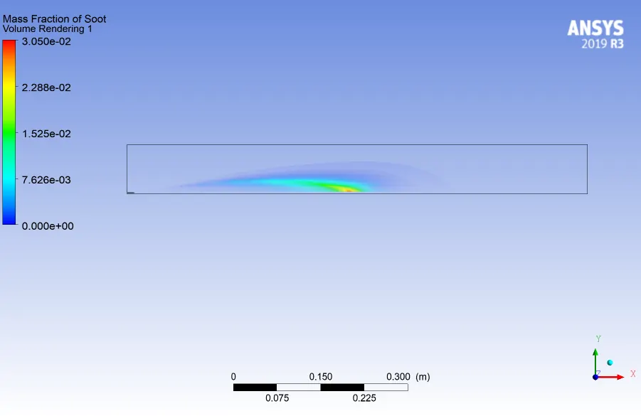
3. Contour & Volume rendering plot for massfraction of soot:
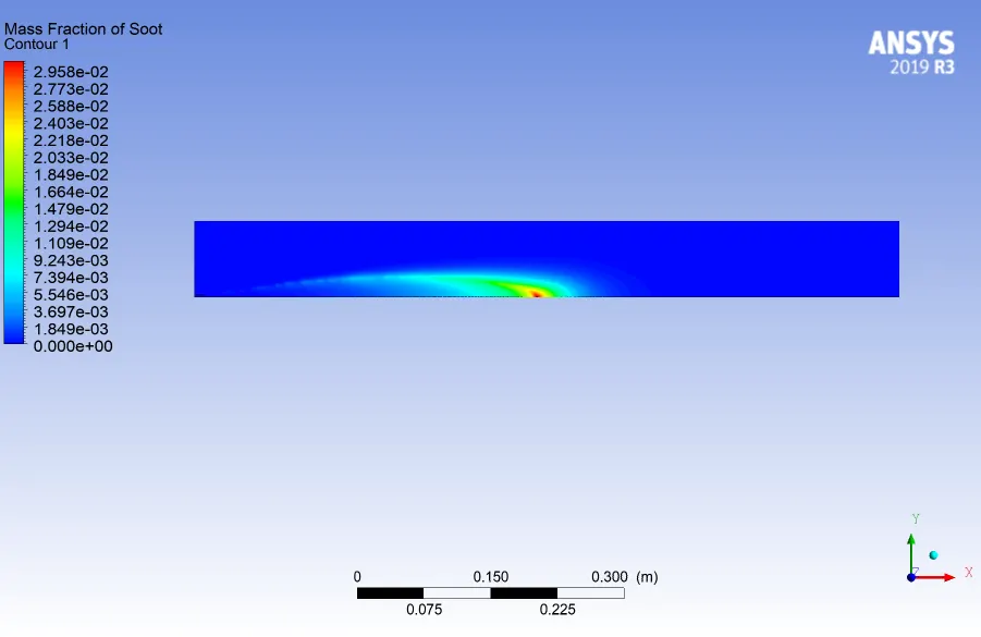
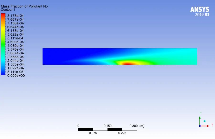
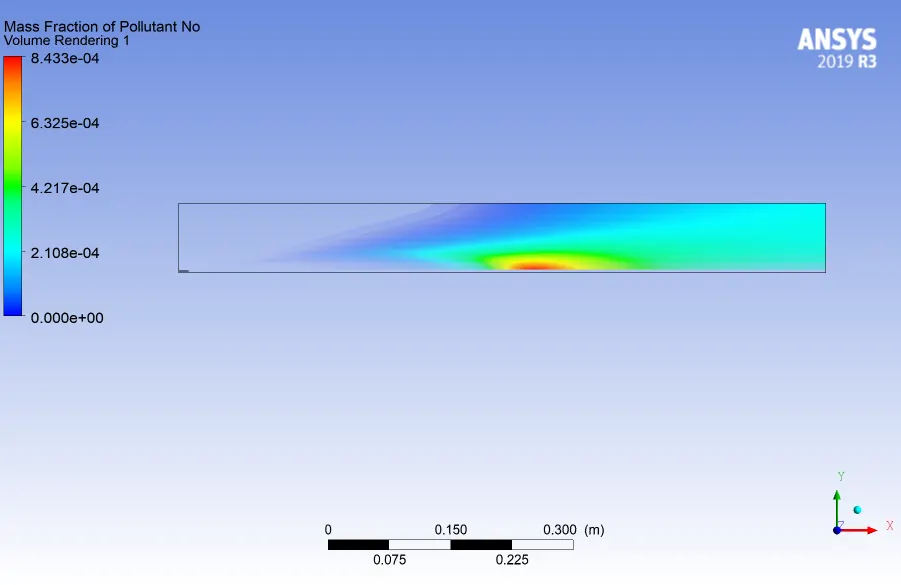
4. Contour & Volume rendering plot for massfraction of NO:
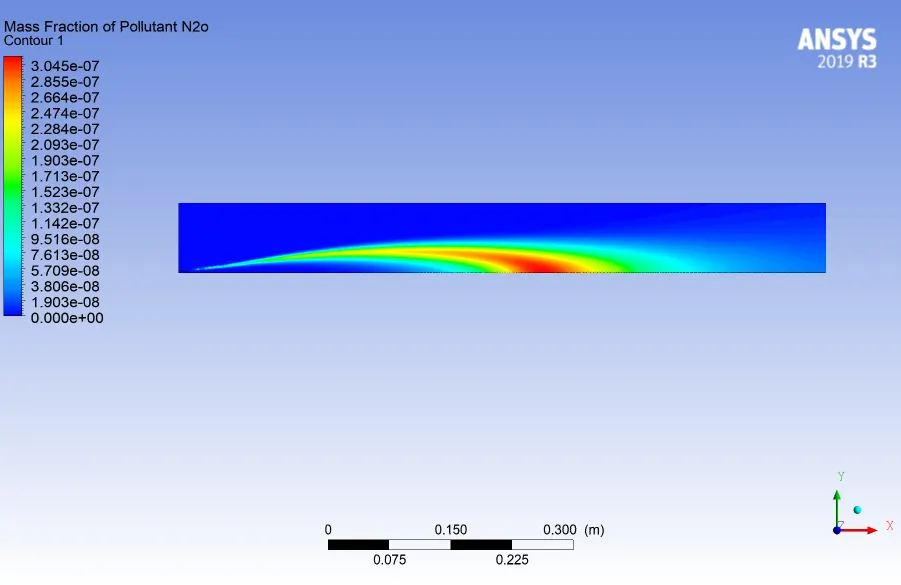
5. Contour & Volume rendering plot for massfraction of N2O:
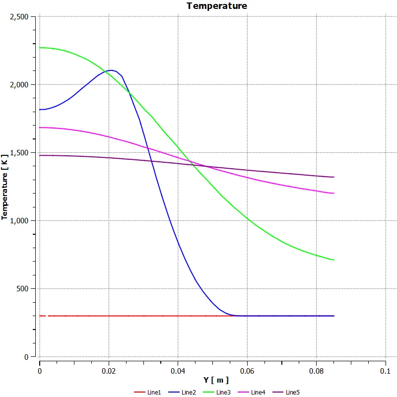
Line plots on the model is show below:
- Variation of temperture along the line plotted:
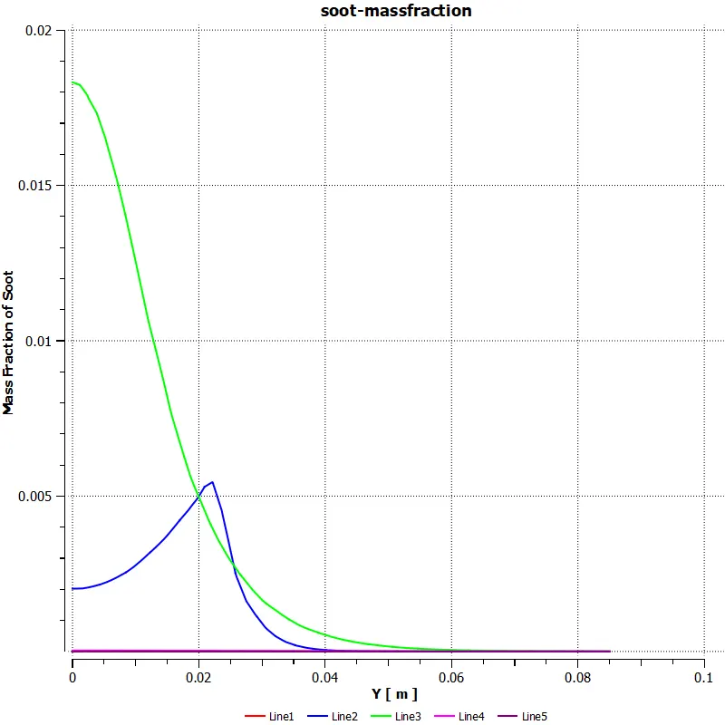
- Variation of soot formation along the line plotted:
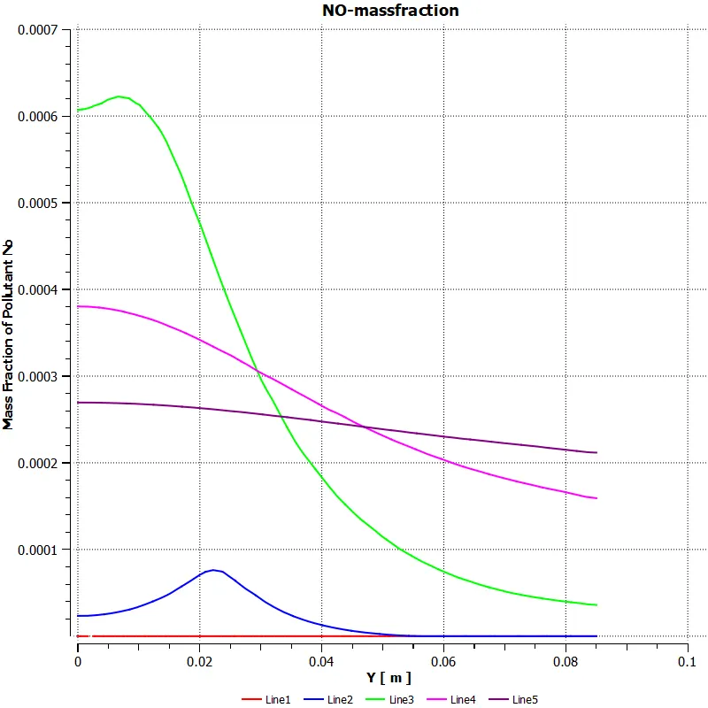
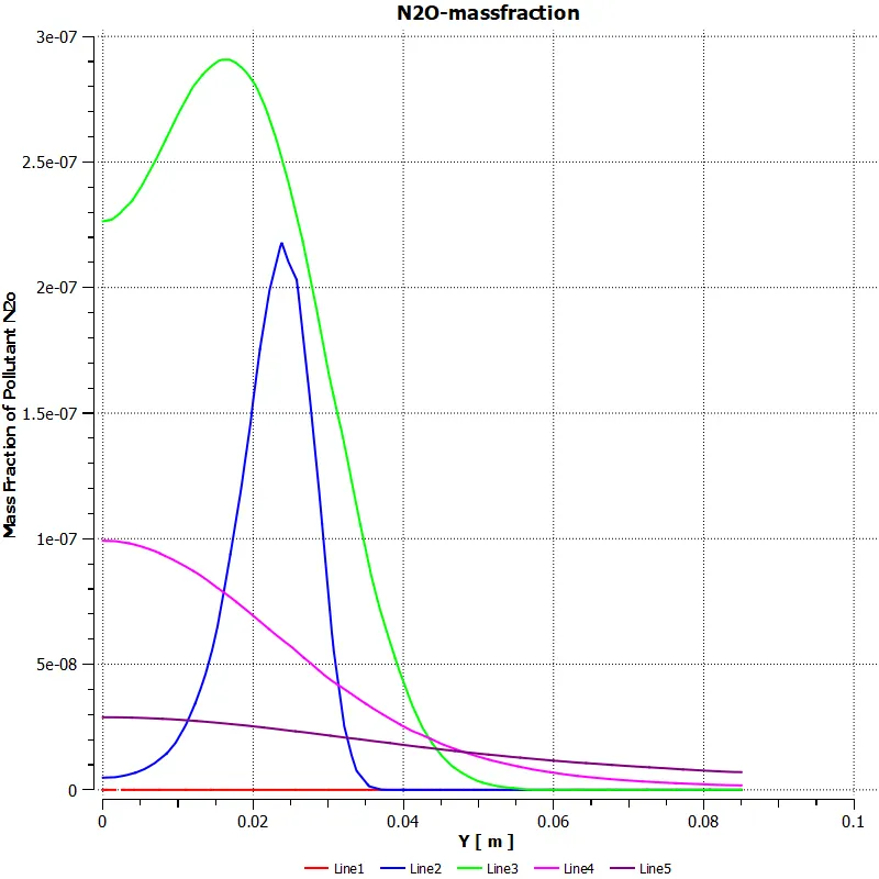
- Variation of NOx formation along the line plotted:
Design Point 4:
mole fraction of ch4 = 0.75
mole fraction of h2o = 0.25
1.Residual:
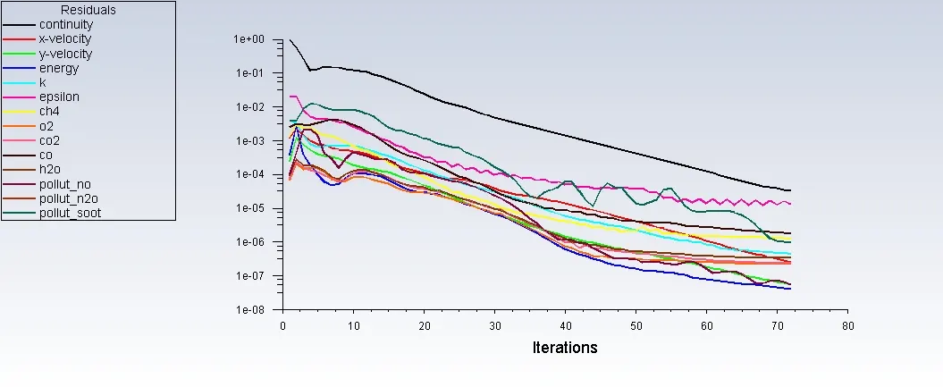
- Solution converged at about 72 iterations.
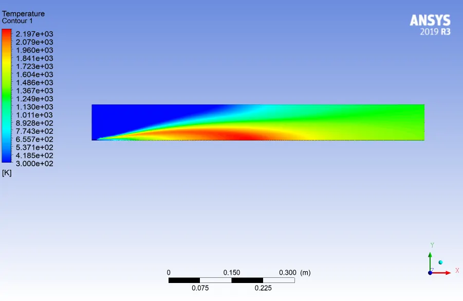
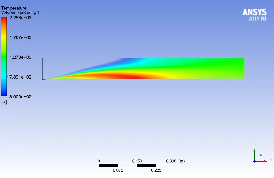
2.Contour & volume rendering plot for temperature:
3.Contour & volume rendering plot for massfraction of soot:
4.Contour & volume rendering plot for mass fraction of NO:
5.Contour & volume rendering plot for mass fraction of N2O:
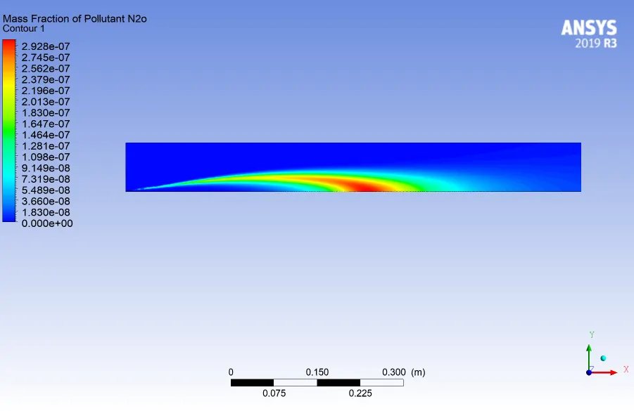
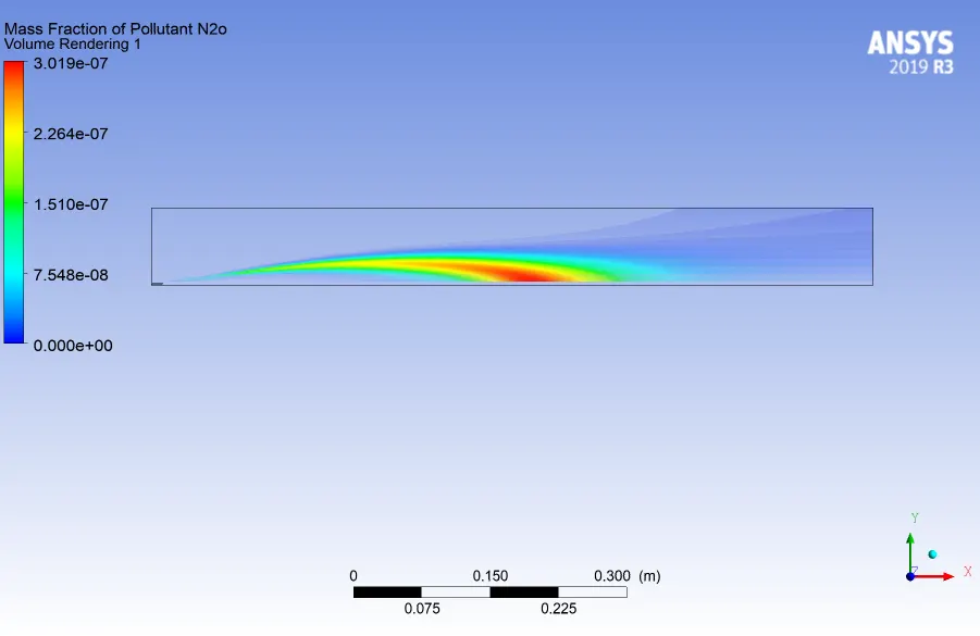
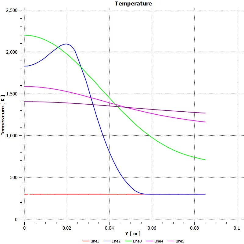
Line plots on the model is shown below:
- Variation of Temperature:
- Variation in massfraction of soot:
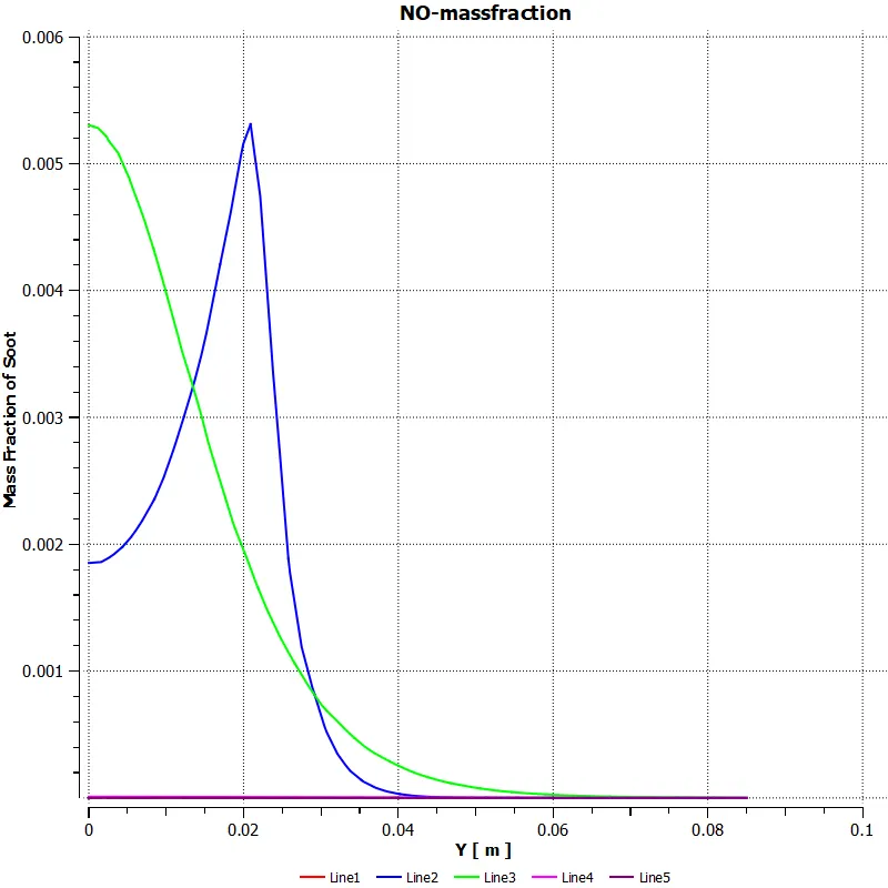
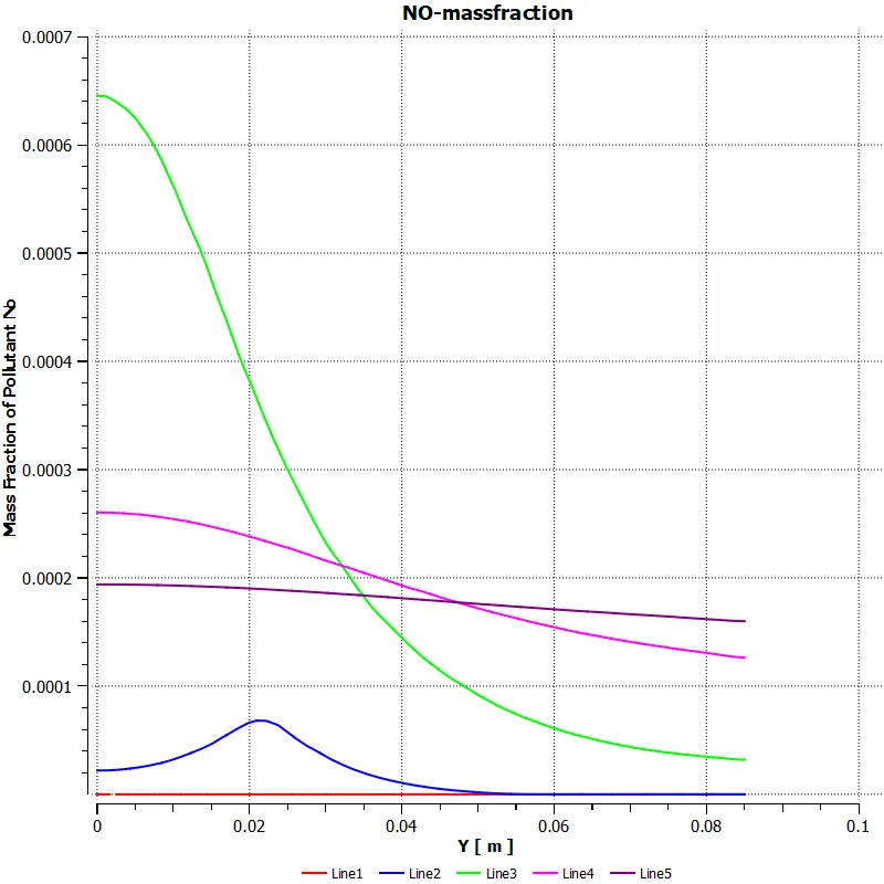
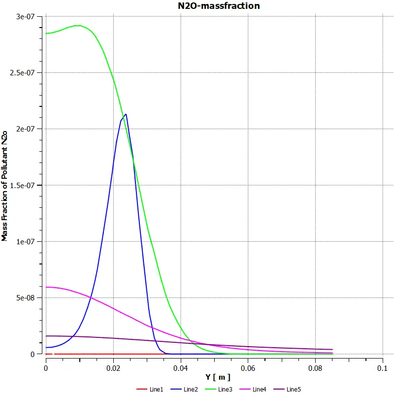
- Variation in massfraction of NOx:
Design Point 5:
mole fraction of ch4 = 0.70
mole fraction of h2o = 0.30
1.Residual:
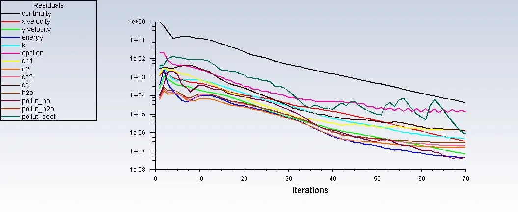
- Solution converged at an iteration of 70
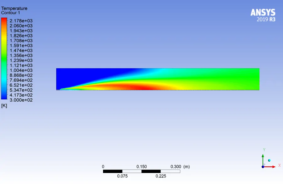
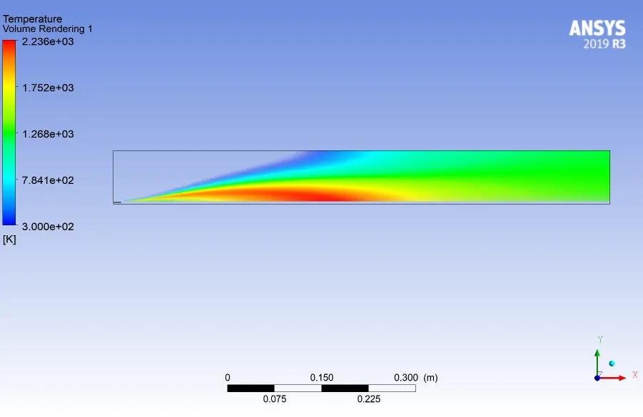
2.Contour & volume rendering plot for Temperature:
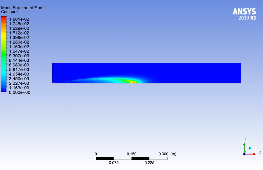
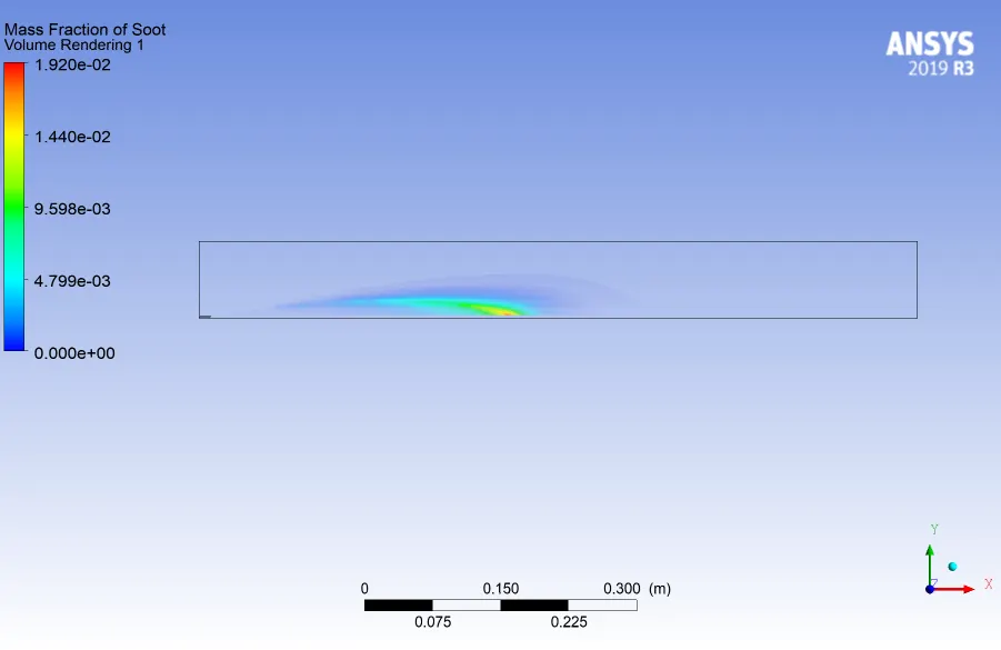
3.Contour & volume rendering plot for mass fraction of Soot:
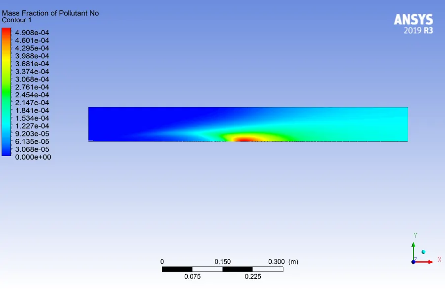
4.Contour & volume rendering plot for mass fraction of NO:
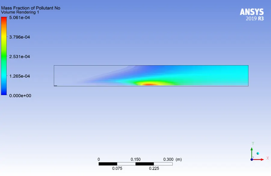
5.Contour & volume rendering plot for mass fraction of N2O
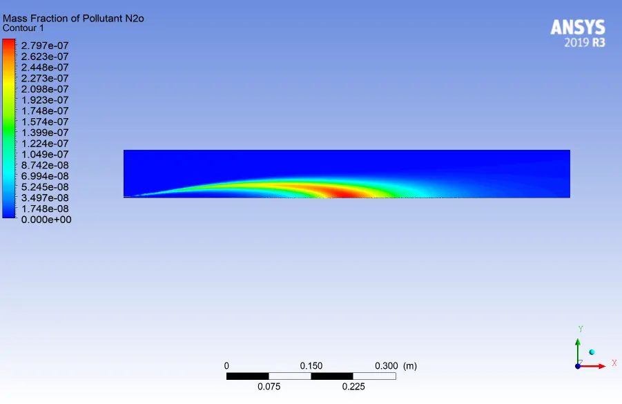
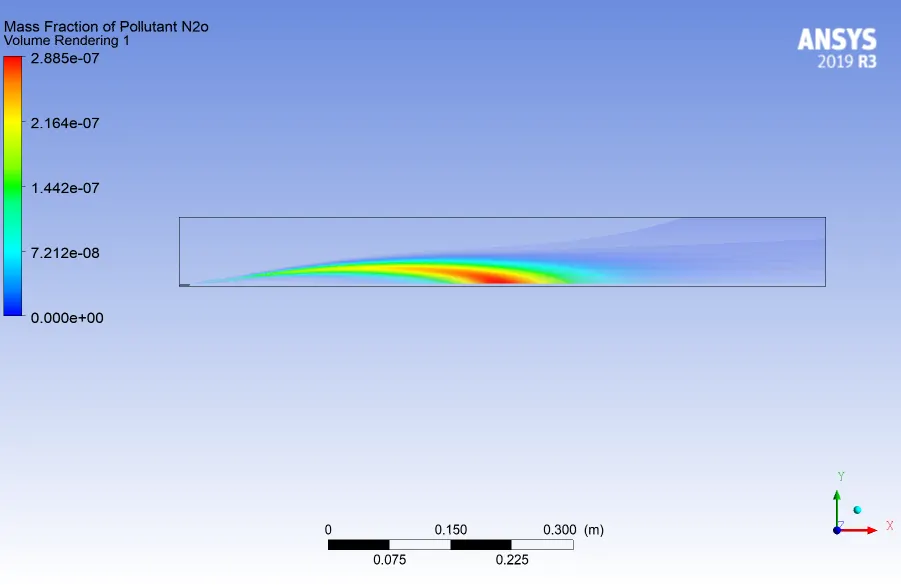
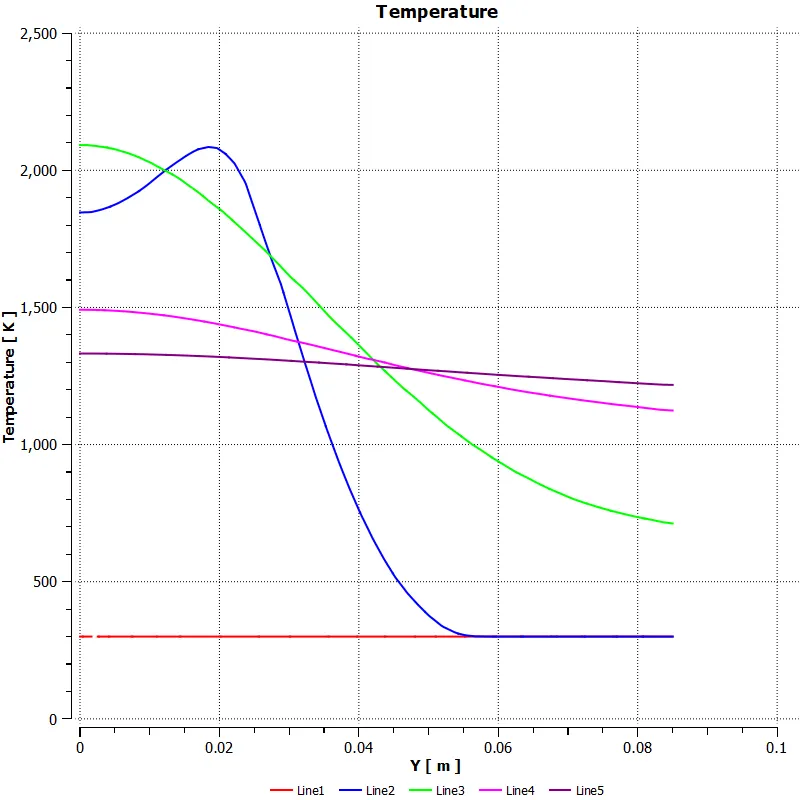
Line plots on the model is shown below:
- Variation of Temperature:
- Variation of massfraction of soot:
- Variation of massfraction of NOx:
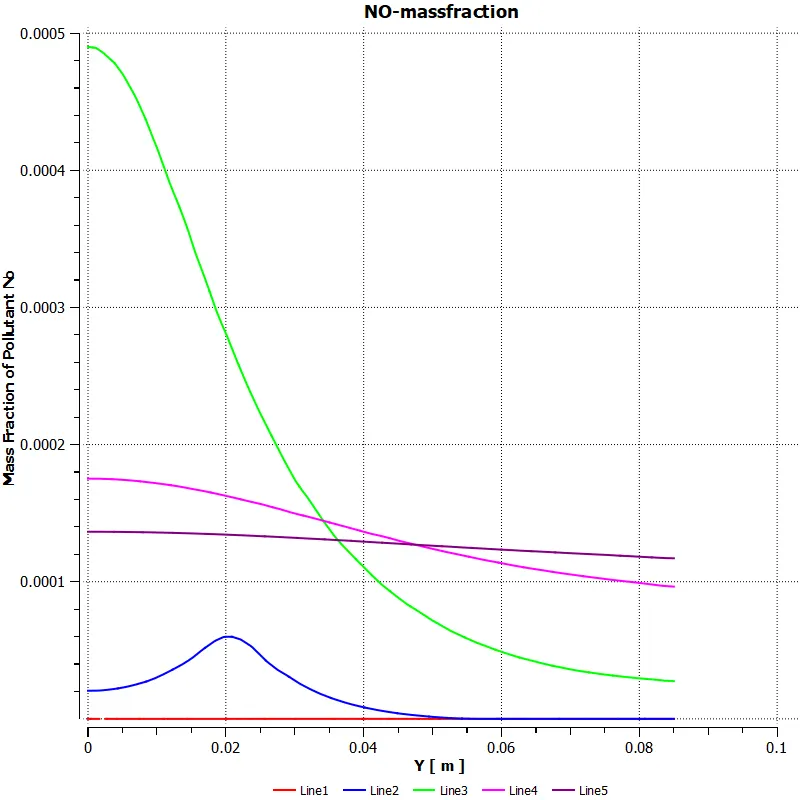
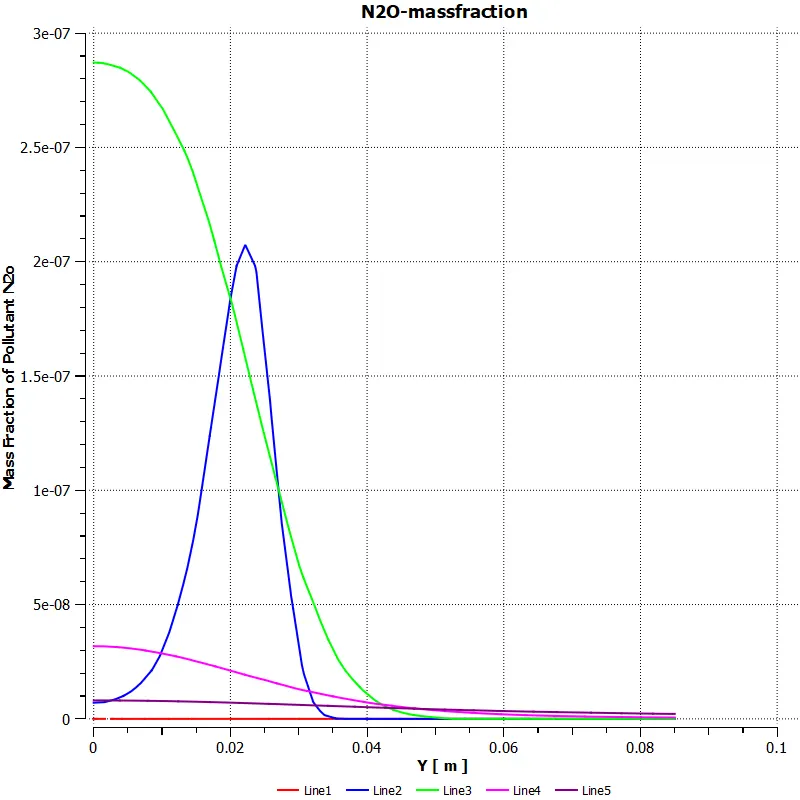
- The mass fraction of the soot,NOx reduces along the length of he combustor during combustion
- The maximum temperature is achieved almost in the middle section of the combustor during the combustion.
CONCLUSION:
Based on the numerical simulation carried out , the following conclusions can be drawn:
-During combustion,the main concern in the cumbustion is the formation of soot and NOx components.
-The components of the soot formed during the combustion was found out to be N2O & NO as the pollutants and among these, mass fraction of NO was found to be more.
-An approach to reduce the amount of the soot and NOx formed was adding water to the fuel in small amounts from 5% to 30% by mole
-By the addition of small amount of water,the amout of soot formed and the NOx is reducing by small amounts
-Whereas the addition of waer , reduces the temperature at the outlet of the burner or the combustor.By addition of water from 5% to 30% to the fuel,the temperature at the outlet is almost reduced by 300 K.This might not be suitable in applications that will be requiring high temperature at the outlet.
-Thus,it can be concluded that ,by the addition of water to the fuel,there is a tradeoff between the temperature at the outlet and mass fraction of NOx and soot.Addition of water reduced the amount of NOx and soot formed and it further reduces the outlet temperature of the flame
ThankYou.